Designing and Installing Distributed Video Systems
Designing andInstalling Distributed Video Systems
In this chapter, you will learn about
- Designing and planning a distributed video system
- Performing a rough-in installation
- Performing a trim-out installation
- Configuring and connecting the components of a distributed video system
A distributed video system is a network of video source and display devices that are interconnected through a house’s structured wiring and a centralized service panel or facility. What a distributed video system can do is allow the output signals produced by a DVD, video cassette recorder (VCR), personal video recorder (PVR), satellite or cable TV, or any other video playback device to be viewed in any room of the house that is connected to the system. No longer will each room need its own VCR, DVD, or receiver in order for multiple viewers in multiple rooms to view the same programs.
Often, a key element of a complete distributed home video system is one or more security surveillance cameras and the associated video monitors. However, that part of a video system is covered in Chapter 35.
Designing a Distributed Video System
The design of a distributed video system should be developed using a systematic approach intended to identify the customers’ objectives and the equipment, cabling, and controls needed to achieve their goals.
Your role in this process, besides that of the designer, is to guide your customers through the maze of choices in equipment, layout, function, and installation to create a distributed video system that meets or exceeds their wishes, while remaining within or below their budget.
Performing the design steps in a certain sequence is the best way to complete the design phase to everyone’s satisfaction. The major steps of the design phase should be
- Identifying and designating the distribution points
- Planning the layout of each room or zone
- Deciding on the control system to be used in each room or zone
- Planning for the centralization of the source equipment
Each of these design phase activities is outlined in the sections that follow.
Designate the Distribution Points
The decision of whether or not any particular room in a house is wired into a whole house distributed video system is strictly that of the homeowner. If the customer wishes to have the bathrooms, laundry rooms, or storage rooms, in addition to the living room, family room, bedrooms, and other living spaces, included in the system, then so be it. However, you should point out that each room should be considered on a cost-benefit basis. In most situations, only the living room, family room, den, one or more bedrooms, and perhaps a home theater or home office are included in a distributed video system. However, the choice is up to the customer.
In a structured wiring environment, the potential distribution points are based on the wiring and where the video system is or will be installed. Where the video system is able to connect to the wiring can, in many situations, predetermine its design and potential distribution among separate rooms or zones.
Essentially, each area of a house that shares a common video signal belongs to the same video zone as any other area also receiving that signal. If the video distribution system is to provide the capability for each room to select its own source device or signal, then each room is potentially a separate zone. Whether a distributed video system is to support one, two, or multiple zones is a key decision that must be made early on in the design phase of the project.
Lay Out Each Room
Unlike a distributed audio system, which should complement the video system, the primary choices for each room are where the video cable will terminate at a wall jack and if a control system or extender is to be installed, what kind is to be installed and, if applicable, where it is to be located. In most situations, these issues are usually considered during the planning of the structured wiring.
| CROSS-REFERENCE |
See Chapter 6 for more information on structured wiring design. |
The ideal situation is to place the video connection in proximity to the video display device. For example, if a standard television in a bedroom is to be connected to the system, then the video connector should be on the wall, behind, or close to the side of the TV set.
Decide on the Control System
One of the most important decisions to be made with designing a distributed video system is the type of controls to be installed in each zone. If all zones are to receive the same video signal, then perhaps only on/off and volume controls are needed in each room for the audio. However, if the intent is that each room can choose its audio source device or video signal, then more sophisticated controls are necessary.
On most zone video display devices, the volume control is part of the same device, like it is on a television set or a computer. However, if a stand-alone video monitor or display device that lacks volume controls is used and the audio portion is to be fed to speakers in the room, the audio portion of the signal must be controlled separately. Video system controls that can be mounted on a wall or other room surface range from relatively simple volume controls to sophisticated LCD touch screen panels and multiple device controllers.
Local Control
The on/off function on any video display device physically located in a zone can be easily controlled from a local handheld remote control or on the device itself. This allows for local control of the display device (on/off/source/channel). It also allows for control of the audio if the audio comes directly from a display device such as speakers built into the television. When the audio of the local video display device has been integrated into an audio system, it can be controlled manually with a volume control.
Volume controls are typically rheostat controls that look very much like the dimmer dials used with lighting systems (see Figure 18-1). The idea is simple: turn the dial to turn up or turn down the volume. Most rotary dial volume controls have 8 to 12 volume level settings and an on/off position as well.
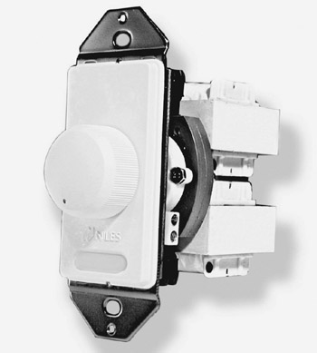
Figure 18-1: A wall-mounted volume control to control the audio portion of a distributed video system
Photo courtesy of Niles Audio.
| CROSS-REFERENCE |
See Chapter 15 for more information on audio control. |
Multiple Device Control
If the customer wishes to be able to control a centralized source device from a zone, some form of remote controller is necessary. Multifunction controllers, on the low-end, are all-in-one handheld remote controls like the one shown in Figure 18-2. These devices can be easily programmed to control multiple source devices, provided line-of-sight between the control and each device is possible.
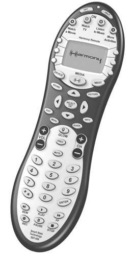
Figure 18-2: An all-in-one remote control unit
Photo courtesy of Intrigue Technologies, Inc.
The technology of handheld and hands-free remotes is evolving quickly. For example, the remote shown in Figure 18-3 can be operated as a handheld remote control, or as a hands-free remote using voice-activated commands.

Figure 18-3: An Invoca remote control that can be used as either a handheld or a hands-free remote
Photo courtesy of Brookstone Company, Inc.
Controlling a Centralized System
Regardless if the home video system is in one or multiple zones, the key to ease-of-use is the ability to control the centrally located equipment from any remote listening or viewing location. The best approach to controlling a home audio visual (AV) system is through the use of distributed remote controls that transmit control signals back to the central equipment as if the user were standing right in front of it.
The most popular ways of controlling a connected AV system from a zone are
- Wired infrared (IR)Wired IR is considered to be the most foolproof way to control remote devices. It incorporates an IR receiver placed in a remote location, such as a master bedroom, which is then wired to an IR emitter that has line-of-sight to the equipment being controlled, such as a CD player in the family room.
CROSS-REFERENCE See Chapter 17 for more information on IR control.
- Wireless infrared (IR) or radio frequency (RF)Wireless is generally considered a single zone solution, but this method is the easiest and least expensive to implement and use. How this approach works is that the IR beam or radio frequency (RF) signal produced by the wireless remote control is received by a receiver located either in the same room (in the case of IR, it requires line-of-sight) or within a 100-foot range and converted into either a RF signal or a powerline control (PLC) signal that is transmitted to a base station attached to the device being controlled. An example of this system is shown in Figure 18-4. This device converts IR signals from a handheld remote control into RF signals that are transmitted to the receiver, where the signals are converted back into IR and “flashed” to operate the electronic equipment.

Figure 18-4: The PowerMid IR Extender System converts IR signals into RF for transmission to a base station.
Photo courtesy of X-10 Wireless Technology, Inc.
IR and RF extender systems are also available that translate the control signal for transmission over a PLC system to a receiver connected to the central equipment.
| Note |
We assume you realize that a signal extension system is only needed when you are not in the same room as the equipment being controlled. In a single zone setup, where the entire home is one large listening zone, an IR or RF signal may need assistance reaching your single set of AV equipment. |
- IR over coaxial cableIf coaxial cable has been placed in multiple rooms or zones, it can be used to send IR commands to the central video system. The coaxial cable must be home run back to the AV equipment for this to work.
- Discrete controllers in multiple zonesIf the design goal of the AV system is to supply a completely discrete set of sight and sound streams to every room in the home, a controller can be set up to communicate with and control the centralized AV equipment. This discrete controller can be hard-wired back to the equipment or communicate by RF to a base unit back at the equipment location that communicates with the AV equipment (see Figure 18-5), using one of two basic methods:
- Direct home-run wiring from the controller to the central AV equipment using Cat 5 wiring.
- IR controllers communicating to a base station device connected via home-run wiring or RF to the central AV equipment.
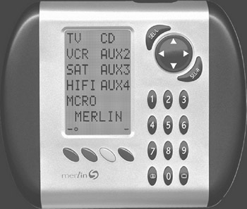
Figure 18-5: A handheld remote control device that can control up to nine discrete devices using IR signals
Photo courtesy of Philex Electronic, Ltd.
In either case, the discrete room controller must either be able to receive the signals from original equipment remote controls or be a replacement device that consolidates as many of the separate remote controls as possible. These devices can be handheld (see Figure 18-5), wall-mounted, or tabletop (see Figure 18-6).
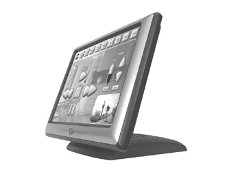
Figure 18-6: A tabletop touch screen AV controller
Photo courtesy of AMX Corp.
Centralizing the Sources
For new construction or in remodel projects where it’s easier to run cable from each zone back to the centralized A/V equipment, the use of direct and dedicated cable runs is definitely preferred over other signal transmission schemes. IR or RF signals can be converted by in-zone receivers and transmitted over the wire back to the centralized equipment.
Select the location of the central equipment and the wiring panel associated with it. All of the cables from the different rooms or zones should terminate here along with the wiring from all external sources (cable, telephone, satellite, antenna, and the like) that provide the video signals that are to be distributed throughout the house.
| Note |
Since most locations will include structured wiring and a structured wiring distribution panel, the video or audio cabling should eventually terminate at the distribution panel, where it can be connected to the cabling that distributes it throughout the house. |
The location of the equipment should meet the homeowners’ design, accessibility, and usage needs. Many homeowners wish to display their equipment in a nice rack arrangement in a prominent location. Others may place this equipment in a closet, utility room, or another out-of-view location. Of course, the homeowner could also hide some from view and display the really cool pieces, kind of like electronic artwork.
Depending on your customer’s desires and budget, the equipment found in the central hub location may include the following.
- AV controller
- Cable TV converter
- CD player/burner
- Digital satellite system (DSS) receiver
- DVD player/burner
- Internet gateway
- PVR
- VCR
- Digital media storage device
- Video distribution panel
CROSS-REFERENCE See Chapter 16 for more information on audio video components.
Installing Video Cable
Video distribution transmits RF signals over physical cable, which is typically shielded coaxial cable. A coaxial cable is able to carry more than 130 standard channel frequencies and a major part of delivering a quality signal to produce a quality image is keeping the video signal in the cable and other signals that might interfere outside the cable. Each channel transmitted on the coaxial cable has both video and audio components, and with MPEG Transport Streams (MTS) encoding in use, each channel can also carry stereo sound.
A coaxial cable is able to carry many channels and their signals at the same time. However, baseband signals, like those produced on a VCR or DVD player, require an entire cable for each channel. So, transmitting the entire baseband AV output from a VCR player requires two coaxial cables or a coaxial cable and separate audio cables.
For the best results, use quality RG6 coaxial cable (or a wireless RF system) to distribute video signals throughout a home. Depending on the design of the system, each room included in the distributed video system should have at least one cable connection jack. In rooms where there may be one or more video sources, additional jacks should be installed.
Another design consideration is the load on the video cabling. Remember that 6 decibels (db) of signal is lost for each 100 feet of RG6 cable. If the number of devices and the cable run lengths add up to too much attenuation, you may want to consider designing in a video amplifier. Also remember that if you use splitters or combiners (typically a hybrid single device), as shown in Figure 18-7, there is also loss when the signal passes through that device as well.
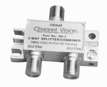
Figure 18-7: A video signal splitter/combiner
Photo courtesy of Channel Vision.
| CROSS-REFERENCE |
See Chapter 17 for more information on video signal loss and calculation. |
The cables that work best with different video applications are
- CoaxialThis cable is the standard used for cable television connections. It is typically terminated with a barrel Bayonet Neill Concellman (BNC) connector, but it can also be terminated with an RCA connector. Although other applications are in development, coaxial cable is used primarily for antenna and cable inputs.
- Component (also called digital component)The newest of the cable and connector types that provides the best picture quality. The video signal is separated into three separate signals (Y, R-Y, B-Y, where Y represents black and white luminance, R represents red, and B represents blue) and results in better color and clarity. The connection for a component cable has three plugs, one for each color component. Make sure the colors are matched to the device jack colors.
- CompositeA standard video signal format that contains the color, brightness, and synchronization information. Virtually all VCRs and other legacy video equipment have composite video input or output. The jacks and plugs used for composite video are RCA connectors. This signaling and connection format is distinctive in that it uses three wires for connections: a yellow jack for video, a white jack for left-side audio, and a red jack for right-side audio.
- S-VideoThe signal is split into two color groups: Chrominance and Luminance. Chrominance carries color information and Luminance carries brightness and lighting information. S-Video is used primarily to transmit video signals to a television from a VCR or game device. The pin configuration on the jack and plug on a S-Video connection prevent the connection from being made incorrectly.
- Video Port (VPort)This connector is primarily used to connect video game devices that have an RCA VPort connector that carries a composite video signal. It was originally designed to host the Microsoft Xbox video gaming device on RCA televisions.
- Digital Video Interface (DVI)This interface connector provides connections for both analog and digital monitors on a single cable. Each of the three DVI configurations is designed to accommodate either analog (DVI-A), digital (DVI-D), or integrated (DVI-I) signals. When a DVI connector and port are used, a digital signal sent to an analog monitor is converted to an analog signal. If the monitor is a digital monitor, like a flat panel display, no conversion is performed.
- High-Definition Multimedia Interface (HDMI)An improvement over the DVI interface, HDMI supports either RGB or YCbCr digital video at rates well above the 2.2 Gbps required by high-definition television (HDTV). HDMI also supports up to eight channels of digital audio.
Rough In Cable Installation
During the rough-in phase of construction, the outlet boxes are mounted and cabling is installed in the walls while the walls are still open. From the outlet boxes, the video and audio cables are run to the location of the central panel. It isn’t absolutely necessary to install the central distribution panel during rough-in, but it can be a good idea, especially if the panel is to be flush-mounted on a wall. Of course, this presumes that a floor plan and wire layout has been created and approved by the customer before you begin the installation of the rough-in items.
Rough-in work is generally done right after the electricians, plumbers, and Heating, Ventilating, Air Conditioning (HVAC) technicians complete their rough-in work and before the wallboard (drywall) is installed. Working after the electricians, plumbers, and other technicians allows you to install the cable so that it has the minimum distance and clearance from electrical wiring and any other objects inside the walls. Table 18-1 lists the minimum distances that AV cabling should be from the other fixtures in the house.
|
Fixture |
Minimum Distance |
|---|---|
|
AC electrical cable |
6 inches |
|
Motors and motor wiring |
12 inches |
|
Fluorescent lighting and wiring |
24 inches |
| Note |
Remember that if the video cable must cross an electrical cable, it should do so at a 90-degree angle. |
Passing Through Studs
The structured wiring being installed, which includes the video and audio cabling, can be an inch or more in diameter. To pass the cable through the wall studs, a hole at least 1/8-inch larger should be drilled through each stud along the cable path. Remember the general cable installation guidelines (see Chapter 1) and keep the structured wire bundle the proper distances from the electrical and other wiring that should already be installed. The same process applies even if only a single cable is being installed. Generally, the path for the AV cable can follow the path used by the electricians for the electrical cabling, keeping the proper distances, of course.
Outlet Boxes
A wide variety of low voltage mounting brackets and outlet boxes are available for use, as illustrated in Figure 18-8. The primary issue when selecting outlet boxes for structured wiring, including video and audio cables, is the bend radius of the cable. Coaxial and Cat 5 cable cannot be bent sharply, which may create a problem for inserting the cable into a standard electrical outlet box. For this reason, open back outlet boxes and mud rings, like those shown in Figures 18-8 and 18-9, or standard electrical outlet boxes, commonly called J-boxes, with the backs removed should be used. The common practice for home wiring systems is the use of blue or metallic boxes for electrical systems and orange nonmetallic boxes for structured wiring.
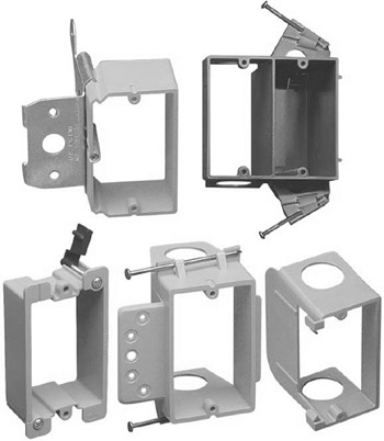
Figure 18-8: A variety of outlet boxes are available to choose from for use with structured wiring.
Photo courtesy of Lamson & Sessions.
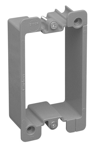
Figure 18-9: An open-back outlet box protects structured wiring from sharp bends.
Photo courtesy of Lamson & Sessions.
It may be necessary to adjust the locations of the structured wiring outlet boxes from the original plans in order to avoid the electrical wiring and other in-wall systems. However, new dual voltage outlet boxes and add-on single and dual gang boxes that accommodate both electrical and low voltage cabling are available. These boxes allow for a common placement of both electrical and structured wiring outlets.
Install the outlet box so that the front edge of it will be inside the hole the drywall installers will cut around the box. The box shouldn’t extend so far out from the stud that it extends beyond the dry wall, but it shouldn’t be so far back that it ends up behind the dry wall either. Check with the dry wall installers, if possible, or the contractor to determine the correct distance the box should extend beyond the stud. Typically this measurement should be either 1/4 or 3/8 of an inch. The box should be placed at the same height from the floor as the electrical outlet boxes, if for no other reason than aesthetics.
Most outlet boxes can be nailed or screwed to an adjacent stud using either the nails already on the box, like those in Figure 18-10, or through the holes provided on the box.
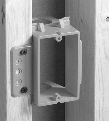
Figure 18-10: A structured wiring outlet box attached to a wall stud
Photo courtesy of Lamson & Sessions.
Trim Out Installation
The trim-out phase of a distributed video system installation project is when the system begins to take shape. Trim-out is when the finish work of the project is done, which includes terminating, testing, and making the connections. This phase of the project has three primary steps:
- Terminating the cable and installing the face plates on the outlet boxes or mud rings
- Testing the cable system
- Configuring and connecting the central video distribution panel and the distributed video sources
Terminating the Video Cable
Terminating the video cable at the outlet box or mud ring involves attaching the cable to the connectors on the back of the wall outlet jack. If coaxial cable is used, then the raw cable must be terminated with a male F connector and then connected to the female connector on the back of the wall outlet. If twisted-pair (TP) cable is in use, the back of the wall outlet will have a 110 punchdown block. See Chapter 2 for more information on coaxial and TP connectors.
The wall outlet used should reflect the systems in its vicinity. For example, if only a television set is in the room, the wall outlet needs to support only an F connector for video distribution. However, if the room also has one or more computer, speakers, and other end devices, a multiple-jack outlet, like the one shown in Figure 18-11, would support the existing requirements and possibly help to future-proof the room.
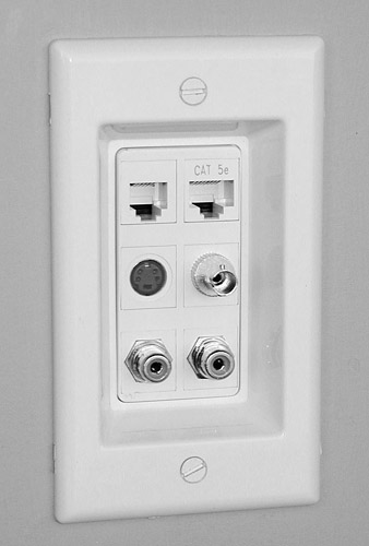
Figure 18-11: A multiuse modular outlet that includes two TP, an S-Video, a BNC barrel, and two F connector jacks
Photo courtesy of SmartHome, Inc.
Trim Out the Central Distribution Panel
As discussed in Chapter 5, the central distribution panel is the key component of a structured wiring scheme. Each of the video cable runs should terminate and interconnect to the cables connecting to the source devices at the distribution panel.
The procedure for connecting the cable runs to the distribution panel is much the same as that for connecting each of the jacks in the wall outlets and uses the same tools. TP cabling is attached to a 110 block on the panel and coaxial cabling is attached using F connectors. It is usually possible for the distribution panel itself to be purchased separately from its enclosure.
A structured wiring or structured media distribution panel interconnects the cabling that runs to rooms with the cabling running from the source devices. The panel shown in Figure 18-12 includes interconnects for TP and coaxial cable as well as room for line support devices, like an impedance amplifier or line converter.
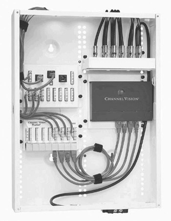
Figure 18-12: A structured media distribution panel
Photo courtesy of Channel Vision.
Testing the System
The first part of testing the system is performing a thorough visual inspection of the wall outlets and the connections at the distribution panel. If anything looks wrong, even slightly wrong, it should be examined very closely and when in doubt, either repaired or replaced.
To test the video cabling system, you should use a cable tester to check the unshielded twisted-pair (UTP) and coaxial cables for bad connections and cable continuity. The next level of testing involves dynamic testing of the cabling using a structured wiring test device, like the one shown in Figure 18-13, to perform the Telecommunications Industry Association / Electronic Industries Alliance (TIA/EIA) TSB-67 tests on TP cabling and the TIA/EIA 570 tests for coaxial cabling.
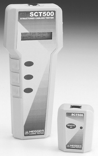
Figure 18-13: A structured cable tester
Photo courtesy of Megger/Avo Multi-AMP Corp.
| CROSS-REFERENCE |
See Chapter 1 for more information on wire basics and wire testing procedures and Chapter 4 for information on cable and test standards for structure wiring systems. |
Equipment Hookup
In general the steps used to connect the video source equipment together and into the distribution system should be performed in a specific sequence. Although the steps in the following list are fairly general (and a particular video system may require some additional or specialized steps), the steps you should perform are
- Remove the components from their boxes in the order you wish to install them. Set aside the product warranty, user guides, and other documents, along with the original remote control, for later use.
- Set the component in the location it will occupy permanently.
- Study the component’s owner’s manual. Make a note of any special hookup instructions required for the device (unplanned connectors, equipment cords, and the like), but don’t hook up the equipment just yet.
- If the video components (cable receiver, digital broadcast satellite (DBS) receiver, DVD-player, videotape player, and so on) are from a single manufacturer, which is somewhat unusual, follow the instructions in the manufacturer’s documentation very closely, using the specified cables and connectors as prescribed.
- However, if the equipment is from several different manufacturers, verify the connector jacks on the backs of the devices and that the devices have common connections between them before beginning to cable the devices together. It is a good idea to “dry run” the system before actually beginning to connect the components together with their cables, just to verify that you have the correct cables and connectors required.
- Connect the video components together and install a small television set on each of the output lines (one at a time) that will supply distributed video throughout the home. Check the video picture and correct any problems at the device, following the troubleshooting guides in the device documentation.
- If the video devices are performing as they should, connect the video output or source lines into the distribution panel and connect to the video splitter or amplifier.
- Retest the system using the small television set at each of the distribution outlets that terminates the video distribution cabling. Once it is verified that the outlets are working, hook up the video devices in each room, working with one device and one room at a time. If there are any problems in the distributed video signal received at the outlets, the problem is likely in the outlet or the cabling it terminates. The cable should be tested using the appropriate equipment and in accordance to the specification of the splitter, amplifier, or end device to which it connects.
CROSS-REFERENCE See Chapter 16 for more information on testing distributed audio/video cabling.
Figure 18-14 illustrates the connections typically made in a distributed video system.
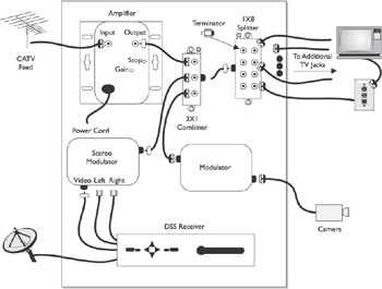
Figure 18-14: The connections made in a video system
Review
There are a variety of video signal formats in use in video distribution systems as well as on computers. The primary video signal formats are: RGB, component, S-Video, and composite. Video signals are either optical or electronic. Optical signals originate from a camera or a scanner and electronic signals originate from a computer’s graphics card.
The common video signal formats are: CATV, composite video, RGBHV, RGBS, RGsB, S-Video, and YCrCb. The three primary broadcast standards are: NTSC, PAL, and SECAM. The best signal format is RGBHV, but it isn’t available in all locations. The most common video signal format is composite, which CATV is part of.
The design phase for a distributed video system involves designating the rooms to be included, laying out the locations for the wall outlets, and deciding on the type of controller for each room or zone.
Each area that shares a common video signal is in the same video zone. Whether a distributed video system is to support one, two, or multiple zones is a key decision that must be made early on in the design phase of the project. The video wall connector should be placed in proximity to the video display device. Video controls range from relatively simple volume controls to LCD touch screen panels and multiple device controllers.
The common controller types are: wireless IR or RF, dedicated device controllers, extended IR or RF controllers, and IR over coaxial cable.
Video distribution transmits RF signals over physical cable, which is typically shielded coaxial cable. A coaxial cable is able to carry more than 130 standard channel frequencies and a major part of delivering a quality signal to produce a quality image is keeping the video signal in the cable and other signals outside the cable. Baseband signals, like those produced on a VCR or DVD player, require an entire cable for each channel. So, transmitting the entire baseband AV output from a VCR player requires two coaxial cables.
RG6 coaxial cable is the best choice for distributing video signals throughout a home, but other cable media can be used, including: coaxial, component, composite, DVI, HDMI, S-Video, and TP.
In the rough-in phase of construction, the outlet boxes and cabling are installed in the walls after the electricians, plumbers, and HVAC technicians complete their rough-in work and before the wallboard (drywall) is installed. The structured wiring is installed to pass through the wall studs.
A wide variety of low voltage mounting brackets and outlet boxes are available for use with structured video cabling. The common practice for home wiring systems is the use of blue or metallic boxes for electrical systems and orange nonmetallic boxes for structured wiring.
Install the outlet box so that the front edge of it will be inside the hole the drywall installers will cut around the box. The box should be placed at the same height from the floor as the electrical outlet boxes, if for no other reason than aesthetics.
During the trim-out phase of a distributed video system installation, the finish work of the project is done, which includes termination, testing, and making the connections. If a room has one or more computer, speakers, and other end devices, a multiple-jack outlet should be used to support the existing requirements and to help future-proof the room.
A key component of a structured wiring scheme is the central distribution panel, which is where each of the zone cable runs terminate and connect into the source devices. The procedure for connecting the cable runs to the distribution panel is much the same as that for connecting each of the jacks in the wall outlets and uses the same tools.
The first part of the testing system is a thorough visual inspection of the wall outlets and the connections at the distribution panel. To test the video cabling system, a cable tester should be used to check the UTP and coaxial cables for bad connection and cable continuity.
Questions
- Composite video and audio that is modulated to allow multiple signals to share a common transmission medium best describes which video signal format?
- RGBHV
- YCrCb
- RGsB
- CATV
- Which of the following is not a standard television coding system?
- NTSC
- ATSC
- PAL
- SECAM
- What is the term applied to an area in a house where everyone receives the same video signal?
- Room
- Video area
- Zone
- Theatre
- If a homeowner desires to control a centralized source unit using an IR remote control from a remote area of the house, what device should be considered?
- RF remote control
- IR extender
- RF extender
- Voice controlled remote
- What is the number of AV channels a coaxial cable is capable of carrying?
- 1
- 16
- 130
- 256
- What is the db signal loss per 100 feet from RG6 coaxial cable?
- 1
- 2
- 4
- 6
- Which of the standard video formats splits the image coding into two groups, one for luminance and one for chrominance?
- S-Video
- Composite
- Component
- DVI-D
- When is the rough-in phase of a structured wiring project performed?
- Before the electrical, HVAC, and plumbing is installed
- Before the wall studs are erected
- Before the drywall is installed
- After the drywall is installed
- What is the minimum distance away from an AC cable that a structured media cable should be installed?
- 3 inches
- 6 inches
- 12 inches
- 24 inches
- During which of the following phases of a structured wiring project should the cable be terminated and tested?
- Prewire
- Rough-in
- Trim-out
- Finish
Answers
- D. This is the signal format used with cable television. The other choices are all standard video signal formats that are used with computer monitors and other such displays.
- B. This is the standards group that deals with HDTV standards. The other choices are transmission and signal formatting standards.
- C. A home can have one or multiple zones. It can have multiple and overlapping audio and video zones.
- B. Another choice would be IR over coaxial cable using wall outlet mounted IR receivers that are cabled back to the source unit.
- C. This is why coaxial cable is a common choice for video systems.
- D. Additional signal loss occurs if splitters or combiners are used.
- A. Most of the other video standards use a single channel to transmit color and brightness information.
- C. It’s best to wait until after the electrical wiring is installed so you can avoid installing structured media cable too close to other wiring.
- B. More is always better, but in a wall that may be difficult. Also remember that if the media cable must cross the electrical wiring, it should do so at a 90-degree angle.
- C. Prior to this phase the surfaces of the walls are not finished and the connectors and plates would be exposed to possible damage. However, continuity testing should be performed in the rough-in phase and then again in the trim-out.
Part I - Home Technology Installation Basics
- Wire and Cable Basics
- Connector Types and Uses
- Wiring Installation Practices
- Codes, Standards, and Safety Practices
Part II - Structured Wiring
- Infrastructure Wiring Basics
- Planning a Structured Wiring Installation
- Rough-In Installation
- Trim-Out Installation
- Troubleshooting Structured Wiring
Part III - Home Computer Networks
- Computer Network Basics
- Computer Network Hardware
- Computer Network Software
- Designing and Installing a Computer Network
- Troubleshooting a Home Network
Part IV - Audio/Video Systems
- Distributed Audio System Basics
- Designing and Installing Distributed Audio Systems
- Distributed Video Basics
- Designing and Installing Distributed Video Systems
- Troubleshooting Audio Systems
- Troubleshooting Video Systems
Part V. Home Lighting Management Systems
- Home Lighting Basics
- Home Lighting Devices
- Designing a Home Lighting Control System
- Installing a Home Lighting Control System
- Troubleshooting and Maintaining Lighting Control Systems
Part VI - Telecommunications
- Home Communication System Basics
- Designing and Installing a Home Telephone System
- Troubleshooting a Home Communication System
Part VII - HVAC and Water Management
Part VIII - Security System Basics
- Security System Basics
- Designing a Home Security System
- Installing a Home Security System
- Troubleshooting and Maintaining a Home Security System
- Home Security Surveillance Systems
- Home Access Control Systems
Part IX - Home Technology Integration
- Defining Users Needs and Desires
- User Interfaces
- Home Automation Controllers
- Programming
- Integrating the Connected Home
- Other Home Technology Integration Devices
Part X - Appendices
EAN: N/A
Pages: 300
