HVAC Controls
In this chapter, you will learn about
- HVAC control equipment
- Installing HVAC controls
- Maintaining and troubleshooting HVAC controls
Heating, Ventilation, Air Conditioning (HVAC) includes the equipment, ducting, and vents that either collectively or separately provide heat, ventilation, or cooling to a home. As indicated by its name, an HVAC system provides three basic environmental services: heating, cooling, and air handling, ventilation, and air quality. Home automation can extend to include controlling a home’s HVAC system. This includes automating the function of the thermostat either on a whole-house or zone basis.
HVAC systems with thermostat control use standardized electrical signals to communicate with external thermostats. It’s that part of HVAC systems this chapter addresses.
Residential HVAC
There are several types of heating and air conditioning systems found in homes, but the primary types are forced air, baseboard and convection, hydronic, and evaporative cooling systems.
Forced Air Systems
Forced air systems use a circulating blower to move heated or cooled air into the rooms of a house (see Figure 29-1). There are two very general types of forced air systems: constant air volume (CAV) and variable air volume (VAV).
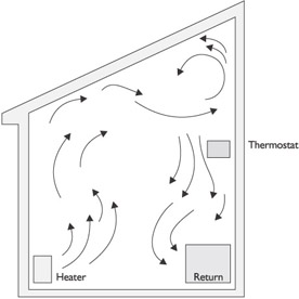
Figure 29-1: A forced air system circulates heated or cooled air to change a room’s temperature.
CAV Systems
CAV systems supply a constant flow of air to the whole house. The central terminal-reheat unit heats or cools its flow of air to heat or cool the coldest or warmest zone in the house. Each zone, an area of a house equipped with a zone terminal-reheat unit and controlled by a zone thermostat, then adjusts the temperature of the central forced airflow to meet its specific heating or cooling needs. These types of CAV systems are also referred to as single-duct systems, and are the most common type of HVAC found in existing homes.
| Note |
A terminal-reheat unit maintains a comfortable temperature in a zone by reheating or cooling the airflow to the temperature set on a zone thermostat. |
In most cases, the airflow into the zone has been partially cooled or heated to a general setting by the central air-handling device. Dual-duct CAV systems supply both cool and warm air, each in its own ducting, to a mixing chamber in each zone. The zone thermostat controls the temperature of the air leaving the mixing chamber by managing the amount of warm and cold air allowed to enter the mixing chamber. This type of CAV system eliminates the need for terminal-reheat units in each zone.
VAV Systems
VAV systems supply air that is heated or cooled to a constant temperature to each HVAC zone. Each VAV zone is controlled by a thermostat that uses a damper to regulate the temperature in each room by controlling the amount of cool or warm air allowed to flow into the zone. Typically, the damper is not closed all the way, which allows some fresh airflow into each zone.
VAV systems offer a number of advantages over CAV systems, including that they cost less to purchase and install, their operating costs are typically lower, and because only those areas requiring heating or cooling receive air, they are more energy-efficient than CAV systems. However, on the downside, VAV systems don’t provide much variability and flexibility when heating or cooling selected zones in a house, because there is only a single air supply and no local zone equipment.
VAV systems also do very little to balance both ventilation and temperature control, and because they generally reduce the volume of heated or cooled air flowing into any particular zone, air quality can be compromised.
Baseboard and Convection Systems
Baseboard devices installed along the baseboards of a wall, typically under a window, can provide heat by either using an internal electric heating element or the flow of air or water to a baseboard or freestanding register from a central gas or oil-fired furnace.
These units can be controlled using several methods. The most common are
- An on/off switch on the unit
- A thermostat controlling one or more local units
- A thermostat controlling the central heating device
Figure 29-2 shows an example of an electric baseboard heating unit.
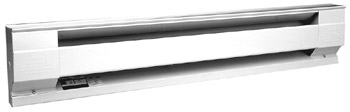
Figure 29-2: An electric baseboard heating unit
Photo courtesy of Cadet Manufacturing.
Although some baseboard, and most in-wall heating, units include air blowers, most baseboard units use convection to heat a room. Convection heating uses the natural phenomenon of heated air rising: when the rising heated air comes into contact with the cooler temperatures of the window surface, the heat is forced outward from the window into the room.
Convection system electric baseboard units or water-flow registers are placed on the floor against the bottom edge of a wall centered under a window in the outside wall of a room. Most convection devices use either an internal electric heating element or a gas-flame heating chamber to heat a room until the room air temperature matches that of an in-room thermostat or a thermostat built into the convection unit itself.
Another type of local heating device is an in-wall electric heating unit, like the one shown in Figure 29-3. These units are either self-contained devices that include an electric heating element, a blower, and a built-in thermostat, or are gas-fired heating chambers that reheat the airflow from a central heating system.
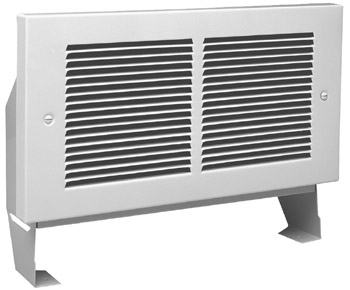
Figure 29-3: An in-wall electric heating unit
Photo courtesy of Cadet Manufacturing.
Those electric baseboard or heating chamber devices that are locally controlled using an in-room or in-zone on/off switch can be connected into a home control system and centrally controlled using relay switches. In those units that are controlled using a room thermostat, the thermostat is typically limited to turning the unit on or off according to its temperature settings. The units that are connected to a centralized control system through a thermostat interface can be controlled remotely.
Hydronic Systems
The term hydronic has recently replaced the term hot water when describing heating systems that use boiler-heated water to provide convection and radiant heating in rooms, floors, ceilings, and even walkways, patios, and driveways.
Hydronic baseboard heating is commonly found in houses built over the past 30 years or so, especially in those areas with colder winters. Well-known for its efficiency and low-operating cost, hot-water heating is also making a comeback largely because of improved and more efficient oil- and gas-fired boiler systems.
Hydronic Baseboard Heating
Hydronic heat uses hot water that is heated in a boiler or some form of a water heater to transfer heat into a room or zone. For room hydronic systems, hot water is circulated through heating elements that have long, thin aluminum-finned radiators; these radiators have largely replaced the tall cast-iron radiators of the past.
The length of the radiator in a particular room is determined by how quickly heat dissipates from a room and the amount of heat required to maintain a comfortable range in that room. The room radiators are incorporated into a continuous loop of copper pipe that loops from room to room. Like other convection heating systems, hydronic baseboard units are placed beneath windows.
Hydronic systems offer several advantages: they are quiet, provide constant warmth, and are fuel-efficient. However, controlling individual zones requires a separate piping and pumping system for each zone. Even with a separate hydronic system for each zone, hydronic systems are either on or off.
In hydronic systems, a boiler heats the water, which circulates through the piping throughout a zone or the entire house. A separate pipe returns the cooling water back to the boiler or water heater. The water is circulated through the system by a circulating pump.
Hydronic Radiant Heating
Another form of hydronic heating gaining in popularity is radiant heating that is embedded or installed inside room floors, patios, driveways, walkways, and other exterior areas where the heat can be used to melt snow or ice.
To install radiant floor heating, the hydronic piping system is either attached to the underside of a floor or embedded in a concrete slab, as illustrated in Figure 29-4. Hot water or some other type of liquid running through the piping heats the flooring or concrete surface, providing warm floors and clear and frost-free exterior passageways.
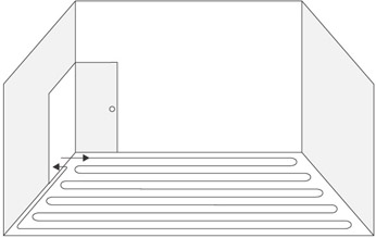
Figure 29-4: Radiant heating coils installed in a home’s flooring
Radiant heating can be zoned to separate rooms or hallways. Using multiple boilers provides more specific settings and control. How the boilers are fueled can vary from natural gas, to fuel oil, to electricity, and even to solar energy to either directly or indirectly heat the water.
Radiant floor heating takes a long time to heat up so it is not a likely candidate for automated control by temperature. A simple on/off remote control makes sense in situations where the home is a vacation home and not always occupied. One benefit to radiant floor heating is it removes the decorative limitations of radiators, vents, outlets, and return vents of other types of room heating.
Central Heating Units
Heating systems are typically defined by their central units, which are typically referred to as furnaces. The common central heating units are
- Electric furnaceInside an electric furnace are resistance wires that heat up when a current passes through them. A circulating fan passes cooler air from inside the house over the heated wires to heat the air and return it into the rooms of the house. Because no exhaust gases are produced, electric heating systems don’t require venting or chimneys.
- Electric heat pumpMany people confuse a heat pump, shown in Figure 29-5, with an air conditioning system because both are exterior devices and their appearances are very similar. Heat pumps use a specific piping system to extract heat from outdoor air, even at very cold temperatures. The heat is then transferred to a coil located inside the house. A blower then blows air over the coil, which warms the air before it is circulated into the heating zones.
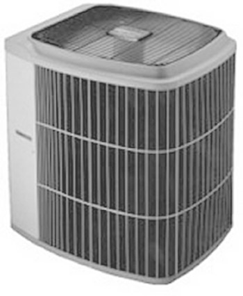
Figure 29-5: An electric heat pump unit is placed outside a home. - Gas furnaceThis type of heating unit is actually a heat exchanger that transfers heat into a home. Natural or propane gas is mixed with air brought in from outside and fired inside a heat exchanger. The exhaust gases travel through the heat exchanger and exit the home through a vent pipe or chimney. A fan circulates cooler air from inside the home over the heat exchanger. The heated air is then circulated through the home’s ductwork into the rooms. Some newer gas furnace models have multiple heat exchangers that improve the heat exchange efficiency and heat the circulating air faster.
- Oil furnaceThe operating principle of an oil furnace is very much like that of a gas furnace. The obvious difference is that fuel oil is used instead of gas vapor. Because the oil is liquid, it must first be converted into a vapor-like mist and mixed with air before it can be burned.
Evaporative Cooling
- An older, but still effective, cooling system is evaporative cooling, which is also called swamp cooling by some HVAC people. Evaporative cooling works on the two principles of water evaporation and the relative humidity of the air. The first principle is that when moisture is added to air that has less than 100-percent relative humidity, the temperature of the air is lowered. The second principle is that the lower the relative humidity of the air, the greater the temperature drop will be when moisture is added to the air.
- In the western United States and other dry-climate areas around the world, evaporative cooling can provide an energy-efficient alternative; it uses one-fourth less energy than compressor-based air conditioning systems.
There are three basic types of evaporative cooling systems:
- Direct evaporative coolingDirect evaporative cooling devices are commonly referred to as swamp coolers because they provide the same cooling effect as a breeze blowing across a swamp, lake, or another body of water. This type of evaporative cooling simply adds moisture to a moving airflow to increase its humidity and thereby lower the temperature of the airflow. However, direct evaporative cooling requires a moving air source with air that is drier than the space being cooled. Commonly, outside air is forced through a constantly wet fiber or corrugated pad by an inner air turbine that also pushes the moistened air into a space displacing drier indoor air. To ensure that the pad stays wet, a recirculating pump pours more water onto the pad than it can evaporate. The excess water flows into a sump to be recirculated. The system replaces any water that evaporates using an automatic valve to refill the sump to a preset depth. Direct evaporative cooling systems are either on or off systems that can be controlled directly or by using a relay switch on a central home system controller.
- Indirect evaporative coolingIndirect evaporative cooling systems are commonly used in larger commercial applications, but there is no reason this type of system can’t be installed on a large home. Like a direct evaporative system, indirect systems use water evaporation to cool air. However, an indirect system does not increase the humidity of the inside air. Rather, it separates the wet side of the process from the dry air used to cool a space. A direct evaporative process is used to cool air or water on one side of a heat-exchanging surface, such as plastic plates or tubes. The heat exchanger transfers the cooling to an air stream that is used to cool a space. Indirect evaporative cooling systems are used either as complete cooling systems or to supplement a compressor-based air conditioning system. These systems are essentially on/off systems and, as a result, can be controlled directly or by using a relay switch on a home system controller.
- Two-stage evaporative coolingThis type of evaporative cooling system uses both direct and indirect evaporative cooling to cool an airflow. In effect, the air flowing into the two-stage unit is cooled using the direct evaporative method. The cooled air is then passed through an indirect cooling system before flowing into a space.
The primary control in a HVAC system is a room thermostat. In some installations, a house may have only a single thermostat for the entire house, but in most new installations, each room or zone of a house will have a separate thermostat.
Thermostats
When selecting a thermostat for a home HVAC system, the first rule is that it must be compatible with the HVAC system. That may sound obvious, but not all thermostats are compatible with all systems.
The more common types of thermostats are
- 220V baseboard thermostatThis type of thermostat is different than nearly all other types because it has to be mounted to an in-wall high-voltage (220V) outlet box. It is not commonly installed in new homes and is typically being replaced.
- Digital thermostatsAlso known as electronic thermostats, this type of thermostat features a digital temperature and set point (the point at which the HVAC system is activated) display. At the low-end price range, digital thermostats are typically mechanical thermostats with a digital display. A digital thermostat draws its operating power (for the display) from one or more batteries or from the 24V HVAC line. Other common features are the auto-changeover switch in the HVAC system between heating and cooling, capability to work with heat pump systems, and capability to be wired to an external control device, such as a motion sensor, timer, or computer-based control system.
- Mechanical thermostatMechanical thermostats are available for heating-only control as well as heating and cooling control. Some models include setback timers, but they typically don’t include an auto-changeover feature. In general, mechanical thermostats are not compatible with heat pump systems.
- Programmable thermostatThis type of digital thermostat allows users to preset heating and cooling changes with a built-in clock (time and day of the week) using a keypad. When the conditions programmed into the thermostat are met, such as either the temperature or clock time, the thermostat activates the HVAC system.
- Remote control thermostatRemote control thermostats are digital thermostats that can be adjusted, programmed, or activated remotely. These thermostats allow the user to change the current set point or heating/cooling mode using a remote control device. The commands sent to the thermostat can be transferred over dedicated wiring from the controller to the thermostat or over the home’s existing AC power lines using power line technology.
Other features that are available on some thermostat models are
- Heating/cooling anticipatorBecause thermostats, both mechanical and electronic, aren’t always located in the same room as that receiving heat, the room can actually be overheated by the time the temperature at the thermostat reaches the set point. A heating or cooling anticipator is an adjustable setting inside the thermostat that turns off the HVAC system at a point that anticipates the desired condition, turning off the heating or cooling system early. A heat anticipator is one way to compensate for a less-than-perfect thermostat location.
- Remote temperature sensorIn many houses, the thermostat is not placed in the best possible location, but in an adequate location where it can be easily accessed. By placing a temperature sensor in a location where it can sense the desired room or zone temperature readings accurately, the thermostat may better serve the heating and cooling needs of the homeowner, so its placement isn’t as critical. A remote temperature sensor, like the one shown in Figure 29-6, can be used to trigger the set point on a thermostat; this way, the homeowners don’t have to rely on the thermostat’s built-in thermometer. Remote sensors can be connected to the thermostat directly using thermostat wire or using power line technology.
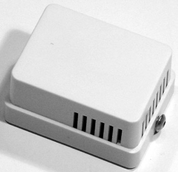
Figure 29-6: An indoor remote temperature sensor
Photo courtesy of Residential Control Systems, Inc.
Control Thermostats
Powerline communication (PLC) thermostats are remote control thermostats that allow the user to change the current set point or heating/cooling mode using a remote control device. The commands sent to the thermostat are transferred over the home’s existing alternating current (AC) power lines using PLC technology.
There are two basic types of PLC-compatible thermostats:
- One-wayThis type of remote control thermostat carries commands to the thermostat, but doesn’t have the capability to carry any feedback back to an X10 remote control device. Some one-way control thermostats are compatible with telephone responder units that also allow the thermostat to be controlled remotely through a telephone, though they are only one-way with no feedback.
- Two-wayThis type of remote control thermostat has the same capabilities as a one-way device but it is also able to transmit information, including the temperature, set point settings, and current mode, back to the controlling device.
Other types of remote control thermostats are currently available, including Electronic Industries Alliance (EIA)-232 and EIA-485 devices. These devices use serial interfaces to provide a reliable high-speed connection that is directly compatible with computers (EIA-232) or can be networked with other sensor and control devices (EIA-485).
HVAC Zones
Creating HVAC zones in a house can save energy as well as better serve the heating and cooling needs of different areas of the house. Many people confuse zones with independent systems where each area has a separate HVAC system. Zoning a house involves the design and installation of a series of airflow dampers that control the ambient temperature separately from other zones or areas of the house using a single HVAC system.
A single zone system or, in other words, a single HVAC system doesn’t require damper systems; the whole house is a single zone with one ambient heating and cooling environment. A multizone HVAC system has at least two airflow dampers, with each damper managing the airflow into one specific zone and independently controlled by a thermostat.
Zoning is recommended in homes that have any of the following characteristics:
- Multiple levels or floors
- A widespread design, such as homes with separate building wings or large ranch-style layouts
- Rooms with large window surfaces
- Large open architecture areas with vaulted or cathedral ceilings, an atrium, or a solarium
- Living space in a finished basement or attic
- Rooms with exposed concrete flooring (such as in a basement)
- An indoor swimming pool or spa
- Earth-shelter houses that have only one or two exterior walls
HVAC Zone Controllers
A standard HVAC system typically has a single thermostat that controls the heating and cooling for an entire house. A zone control system connects two or more thermostats to a single HVAC system. The thermostats aren’t the zone controllers; rather, there is a master zone control device that is connected to the thermostats in each zone, the HVAC system, and each airflow damper.
The master zone controller reacts to the set points of the zone thermostats and opens or closes the dampers, which are located inside the source HVAC ducts leading to each zone. In their normal state, the dampers are open, but the controller can shut them to close off the flow of heating or cooling to a zone.
The zone thermostat operates normally to call for heating or cooling according to its set points. However, the zone thermostat signals actually go to the master zone controller that controls the HVAC system and adjusts the dampers according to the zone settings.
The criteria for selecting a zone controller, such as the unit shown in Figure 29-7, are the number of zones, the type of HVAC system in use, and the size of the house. The size of the house is especially important, as is if the house has more than one story or levels, such as a two-story, three-story, or a tri-level house. In these situations, the master zone control unit should include a thermal equalization capability that balances the ambient temperature of the different levels.
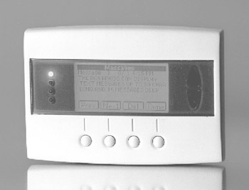
Figure 29-7: An HVAC zone control unit
Photo courtesy of Residential Control Systems, Inc.
HVAC Zone Design
HVAC zoning is very difficult to add to an existing HVAC system, so for the most part, zoning is a new construction application. Not many home automation firms take on the job of designing the actual HVAC system, the ductwork, or the location of the airflow registers, so leave this part of the job to the HVAC and mechanical engineering people.
Once the HVAC system is designed, the design of the HVAC zoning can be done using the following steps:
- Establish the number of zones.Typically, a two- (or more) story house has at least two zones, but the goal is to establish HVAC zones that are roughly the same size in area. The zones shouldn’t be too small because they will be difficult to control, or too large because they may be subject to cold or hot spots. A zone should be created for each separate climatic environment the homeowner desires, typically defined by the activities of the area. For example, a family room where the occupants may be more active can be slightly cooler than a living room where the occupants are less active.
- Adjust the HVAC duct plan to fit the zone design.Ductwork must be designed so that each zone is a separate branch of the main HVAC duct system. The damper for each zone will be installed just after a zone’s ducts branch from the main duct. The volume of the ductwork branches may need to be increased to handle an increased airflow volume. Work with the HVAC specialists to design the volume of the ductwork for a system that is open all the time. Each duct in the system should be able to handle the entire airflow volume of the HVAC system. This allows the system to function normally, even when a damper is closed, without putting too much back pressure on the HVAC system and possibly damaging it. The general rule-of-thumb for increasing the size of the ductwork is to add an additional 25 percent of volume for every two zones on the system. For example, a two-zone system should be increased 25 percent; a four-zone system should be increased 50 percent; and so on.
- Establish the location of the dampers and thermostats.During the pre-wire stage, run two-conductor thermostat wire to the damper locations and five to seven conductor thermostat wire to the thermostat locations. If you are using remote temperature sensors with the system, that wiring must be installed as well.
Zoning Hydronic Systems
Hydronic systems are generally zoned by default, but if you wish to be able to turn the heat on or off in different areas of a home, control valves must be installed in the hydronic piping in the same way that dampers are installed in the air ducts of a forced air system.
Hydronic valves (see Figure 29-8) are motorized to open and close according to the commands of the master zone controller. They open and close the flow of water through the hydronic system.
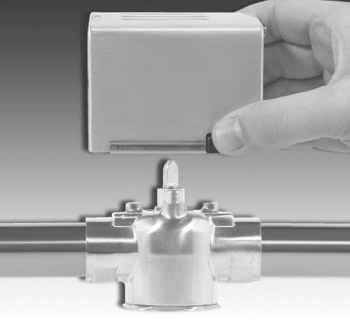
Figure 29-8: A hydronic motorized value
Photo courtesy of Invensys Building Systems, PLC.
Locating a Thermostat
For the best results, a thermostat should be located on an inside wall in an area that is frequently occupied. The thermostat should be at least 18 inches from any outside walls and at least 5 feet above the floor. It should also be placed in an area with freely circulating average temperature air. A thermostat should not be located in any of the following areas:
- On an outside wall
- In direct sunlight or near any heat produced by any closely placed appliances
- Near or in line with a heating or air conditioner vent, a stairwell, or an outside door
- Near any device that produces electrical interference
Note Some thermostats are “power-stealing” units. This type of thermostat takes power from the “W” (see Table 29-1 later in the chapter) heat connection running from the HVAC system. If multiple zone control units are also being installed, don’t connect a power stealing unit or an older style mechanical or anticipator type thermostat to the controller. Neither of these thermostats will work properly with an HVAC control unit.
Wiring a Thermostat
The wiring used to connect a thermostat to the HVAC systems must be no less than 20-gauge wire, and for wire runs longer than 100 feet, 18-gauge wire is highly recommended. Thermostat wiring is different from other wire, such as Cat 3 or 5, audio/video, or speaker wiring. Thermostat wiring has two to seven conductors (see Figure 29-9) of solid core wiring with the color-coding for a seven-wire cable consisting of white, red, green, blue, yellow, brown, and orange. Most HVAC central unit controls, which the thermostat wire connects to, use from five to seven conductors. However, in new construction situations, installing seven-conductor thermostat wire adds to the future proofing of the house.
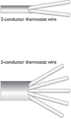
Figure 29-9: Examples of two- and five-conductor thermostat wiring
Standard HVAC ThermostatTypically, the HVAC technicians install the wiring for a central-system thermostat at the time the HVAC systems are installed. The wiring for the thermostat normally is either two- or four-conductor wiring to support either 24V or 120V systems, depending on the needs of the HVAC system and the thermostat planned into the HVAC system. If the plan is for the home system technician to install a standard thermostat, you will need to follow the thermostat manufacturer’s wiring diagram. Figure 29-10 shows an example of a wiring diagram for a typical nonautomated, or noncommunicating, thermostat.
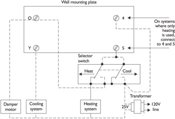
Figure 29-10: A sample wiring diagram for a standard thermostat
When connecting the thermostat wire to the thermostat terminals (see Figure 29-11), strip about -inch of the insulation at the end of each conductor. On most standard thermostats, the terminals are marked with either stickers or embossed letters in the thermostat’s plastic that indicate which wire color should be connected to which terminal. Wrap the exposed end of the conductor wire clockwise around the terminal screw. The manufacturer’s wiring diagram and documentation should also have these details.
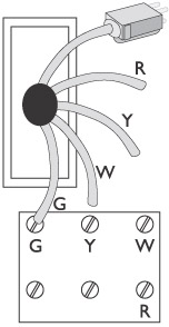
Figure 29-11: Installing the wiring on a standard thermostat device
| Note |
Of course, you already know that regardless of the type of wiring in use for the thermostat, you should turn off the power at the AC circuit breaker panel before beginning to attach the wire to the thermostat. |
Remote Controlled Communicating ThermostatIt is more likely that if the system installation plans for a home include the home technology technicians installing a thermostat, the thermostat is one that can be remotely controlled by some form of remote control unit and is able to communicate with a central home system control unit either with radio frequency (RF) or PLC signals.
The basic wiring for a remotely controlled thermostat is typically very similar to that of a standard thermostat. However, additional installation steps are usually required to accommodate its communications functions.
If the thermostat uses RF signals to communicate to a receiver module located near the HVAC equipment or a home system controller, follow the manufacturer’s guidelines for range and placement in a room. For example, most manufacturers recommend that an RF thermostat be place at least five feet from the floor and not behind a door or other large object in a room.
If the thermostat uses PLC signals to communicate to a home system control unit, at least two devices must be installed and possibly three. This includes one or more wall display units and a control module that serves as an interface between the display units and either the HVAC system (see Figure 29-12) or the home system control unit, and possibly a separate communications module for remote control access. Figure 29-13 shows the modules of a three-part PLC thermostat system.
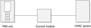
Figure 29-12: An illustration of the general installation of a PLC thermostat
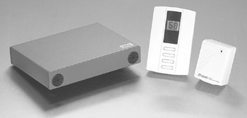
Figure 29-13: The components of a PLC remote control thermostat system, with the controller (left), thermostat (center), and the PLC module (right)
Photo courtesy of Smarthome, Inc.
Rough-InIf the HVAC wiring is going in before the HVAC system, meaning the central HVAC system, first identify the location of the HVAC system. In most houses, the HVAC system is either in a basement, garage, or utility closet. To help with interfacing to the HVAC system, install a low-voltage box on a stud near where the HVAC system will sit. Locate the outlet box so that it is accessible for wiring and hookup. One idea is to place it one foot above the floor (measured to the center of the box). You should leave eight to ten feet of thermostat wire available to later wire the thermostat to the HVAC control.
At the spot where each thermostat will be installed during trim out, leave about one foot of wire slack to connect to the thermostat. During trim out and before the thermostat is attached to the wall and connected to the wire, be sure to seal around the hole the wire is passed through to avoid cold or warm air from the wall effecting the performance of the thermostat.
When pre-wiring for the HVAC control, run the wire from the thermostat and route it by the HVAC system unit (in an outlet box with an eight to ten foot loop) and on to the home control unit. It is a good idea to always prewire for HVAC control, even if not desired initially by the homeowner. By installing the wiring now, it is easy to add HVAC control in the future.
HVAC systems have two levels of wiring: line voltage and low voltage. Line voltage wiring supplies power to the components of the HVAC system, including its condenser, fan, furnace, or boiler. An electrician typically installs line voltage lines. Low voltage wiring for an HVAC system includes the thermostats, zone controls, any relay or control modules, and the control wiring for the system.
Typically, the wire installed for the HVAC control links should be a shielded wire with conductors of not less than American Wire Gauge (AWG) 14. Many local electrical codes require that control wiring be twisted as pairs and referenced to a particular wire type and manufacturer, such as Belden 8760 (single shielded twisted pair) or 8770 (three-conductor shielded twisted resistance temperature devices [RTD] cable). In addition to the shielding on the cable, control wiring should be installed at least a distance of 12 inches from power lines.
At the location of the thermostat, label each wire with the letter code assigned to the terminals of the HVAC system and the thermostat using cable marking tape or masking tape. Label both ends of the cable to ensure conformity. Table 29-1 lists the terminal codes most commonly used in the more popular heating systems. Not every system will have every one of the codes included in Table 29-1 and, in some cases, they may substitute or reassign a wire color or terminal code to another function. Be sure to review the system wiring documentation before labeling the wires to ensure the wires are properly labeled at each end.
|
Terminal Designation |
Wire Color |
Application |
|---|---|---|
|
B |
Blue or orange |
Switch reversing valve on heat pump to heat |
|
C |
Blue, brown, or black |
Transformer common |
|
E |
Blue, pink, gray, or tan |
Heat pump emergency heat relay (not commonly used) |
|
G |
Green |
Furnace fan |
|
L |
Blue, brown, tan, or gray |
Service indicator light |
|
O |
Orange |
Switch reversing valve on heat pump to cool |
|
R |
Red |
Transformer–hot lead |
|
T |
Tan or gray |
Outdoor anticipator reset |
|
W |
White |
Heat |
|
X |
Blue, brown, or black |
Transformer common |
|
Y |
Yellow |
Cooling compressor |
| Note |
Heat pumps have two stages of heating and cooling, while standard gas or electric HVAC systems have only a single stage of heating or cooling. |
Review
The primary types of air systems are forced air, baseboard and convection, hydronic, and evaporative cooling systems. Forced air systems use a circulating blower to move heated or cooled air into the rooms of a house. The two types of forced air systems are CAV and VAV. CAV systems supply a constant flow of air. VAV systems supply heated or cooled air at a constant temperature.
Baseboard heating devices provide heat using an internal electric heating element, or the flow of air or water to a baseboard element. Baseboard units use convection heating.
In-wall electric heating units are either self-contained devices that include an electric heating element, a blower, and a built-in thermostat, or gas-fired heating chambers that reheat an airflow from a central heating system. Electric baseboard or heating chamber devices are either locally controlled or connected to a home control system.
Hydronic heat uses hot water that is heated in a boiler or some form of a water heater to transfer heat into a room or zone. The advantage of a hydronic system is it is fuel efficient. Another form of hydronic heating gaining popularity is radiant heating embedded in floors, patios, and other areas.
The common central heating units are: electric furnaces, electric heat pumps, gas furnaces, and oil furnaces.
Evaporative cooling works on the principles of water evaporation and relative humidity: Adding moisture to drier air lowers the air temperature. The three types of evaporative cooling systems are: direct evaporative cooling, indirect evaporative cooling, and two-stage evaporative cooling.
The common types of thermostats are: baseboard thermostats, digital thermostats, mechanical thermostats, programmable thermostats, remote control thermostats, heating/cooling anticipators, and remote temperature sensors.
Power line thermostats allow the current set point or heating/cooling mode to be changed through a remote control device. The two basic types of PLC-compatible thermostats are one-way and two-way devices.
HVAC zones save energy and better serve the heating and cooling needs of a home’s residents. Zoning a house involves the design and installation of a series of airflow dampers that control the ambient temperature separately from other zones, or areas, of the house using a single HVAC system. A single zone HVAC system doesn’t require damper systems. A multizone HVAC system has at least two airflow dampers where each damper independently controlled by a thermostat. A zone thermostat communicates with the HVAC system and adjusts the dampers according to the zone settings.
A thermostat should be located on an inside wall at least 18 inches from any outside walls and at least 5 feet above the floor in an area that is frequently occupied. The wiring of an HVAC system should be no less than 20 AWG for runs less than 100 feet; 18 AWG wire is recommended for runs longer than 100 feet. Thermostat wiring has two to seven conductors of solid core wiring and the color coding of a seven-wire cable is white, red, green, blue, yellow, brown, and orange.
The wiring for a remotely controlled thermostat is very similar to that of a standard thermostat. However, additional installation steps are required to accommodate its communications functions.
HVAC systems have two levels of wiring: line voltage and low voltage. An electrician typically installs line voltage lines. Low voltage wiring includes the thermostats, zone controls, any relay or control modules, and the control wiring for the system.
Questions
- Which of the following is not a type of HVAC system discussed in this chapter?
- Forced air
- Forced hot water
- Hydronic
- Convection
- What are the two types of forced air HVAC systems?
- CAV
- Hydronic
- VAV
- CAT
- A CAV forced air system is also known as a
- Multizone system
- Single-zone system
- Single-duct system
- Multiduct system
- A heating system that takes advantage of the natural phenomenon that heated air rises and reacts to cooler surfaces to circulate is called
- Forced air
- Induction
- Convection
- Zoning
- Which type of system uses heated water circulating through pipes to heat a room?
- Forced air
- Heat pump
- Hydronic
- Convection
- Which of the following is not a common type of fuel used with central HVAC units?
- Electricity
- Fuel oil
- Heat pump
- Natural gas
- What type of thermostat includes digital displays and the capability to be preset with user-created HVAC settings?
- Mechanical
- Programmable
- Remote control
- Digital
- What is the maximum number of conductors typically available in thermostat wiring?
- Two
- Four
- Five
- Seven
- The wire used for HVAC controls should be what type?
- Shielded AWG 14 single conductor wire
- Shielded AWG 12 2 or more conductor wire
- Unshielded AWG 14 single conductor wire
- Shielded AWG 14 2 or more twisted conductor wire
- What are the areas of an HVAC system that has been separated with a series of airflow dampers that control the ambient temperature of each area separately from the other areas called?
- HVAC zones
- HVAC hot spots
- HVAC controls
- HVAC subsystems
Answers
- B. Nor will you find this system discussed in any HVAC book. All of the other choices are common types of HVAC systems.
- A and C. Constant air volume (CAV) and variable air volume (VAV) are the two types of forced air systems.
- C. There are multiduct CAV systems, but they are most commonly called single-duct.
- C. The heated air from any HVAC system rises—a natural physical phenomenon—and convection heating is built around that principle.
- C. Okay, some convection systems are hot water systems. However, all hydronic systems use hot water.
- C. The “fuel” of a heat pump system is actually electricity, even though its heating process is a heat transfer.
- B. A digital thermostat does have a digital display, but not all digital thermostats are programmable and not all remote control thermostats are digital. Mechanical thermostats are neither.
- D. Although many HVAC systems use five-conductor wire, using seven-conductor wire provides future proofing for the system.
- D. National and local electrical codes recommend shielded twisted conductor wiring of at least 14 AWG.
- A. None of the other answers really apply to this definition.
Part I - Home Technology Installation Basics
- Wire and Cable Basics
- Connector Types and Uses
- Wiring Installation Practices
- Codes, Standards, and Safety Practices
Part II - Structured Wiring
- Infrastructure Wiring Basics
- Planning a Structured Wiring Installation
- Rough-In Installation
- Trim-Out Installation
- Troubleshooting Structured Wiring
Part III - Home Computer Networks
- Computer Network Basics
- Computer Network Hardware
- Computer Network Software
- Designing and Installing a Computer Network
- Troubleshooting a Home Network
Part IV - Audio/Video Systems
- Distributed Audio System Basics
- Designing and Installing Distributed Audio Systems
- Distributed Video Basics
- Designing and Installing Distributed Video Systems
- Troubleshooting Audio Systems
- Troubleshooting Video Systems
Part V. Home Lighting Management Systems
- Home Lighting Basics
- Home Lighting Devices
- Designing a Home Lighting Control System
- Installing a Home Lighting Control System
- Troubleshooting and Maintaining Lighting Control Systems
Part VI - Telecommunications
- Home Communication System Basics
- Designing and Installing a Home Telephone System
- Troubleshooting a Home Communication System
Part VII - HVAC and Water Management
Part VIII - Security System Basics
- Security System Basics
- Designing a Home Security System
- Installing a Home Security System
- Troubleshooting and Maintaining a Home Security System
- Home Security Surveillance Systems
- Home Access Control Systems
Part IX - Home Technology Integration
- Defining Users Needs and Desires
- User Interfaces
- Home Automation Controllers
- Programming
- Integrating the Connected Home
- Other Home Technology Integration Devices
Part X - Appendices
EAN: N/A
Pages: 300
