Installing a Home Lighting Control System
Installing a HomeLighting Control System
In this chapter, you will learn about
- Installing PLC lighting control system
- Installing wired lighting control system
- Installing wireless lighting control system
- Programming Control Options
- NEC compliance in lighting systems
A residential lighting control system provides a homeowner with the ability to control the lighting in a room or zone and to set a variety of lighting scenes in each area. Whenever home technology integration or home automation is discussed, lighting control is almost always included in the conversation. Lighting controls not only provide for better task lighting, they also can be used to “set the scene” through their ability to control the lighting levels in a given area or an entire house. On top of these benefits, a lighting control system can also save homeowners money by reducing energy costs and increasing lamp life.
This chapter covers the installation of the different types of lighting control systems, including the different types of lighting controls, the devices used in setting them up, and NEC compliance.
Power Line Control System Devices
A PLC lighting control system can be a very simple affair, consisting of few plug-in modules and a handheld remote control, or it can be a very complex whole-house system that is controlled by a home automation controller or PC-based home control software. The way a PLC system works is that control commands are sent over the electrical wiring and the appropriate controlled switches or devices respond and execute the command received. An example of coding is in X-10 technology, each of the controlled devices is given a code that consists of a letter (A-P) and a number (1-16). An example would be the kitchen sink light is coded D-4 and the kitchen counter lights are D-5. The command “D-4 ON” would turn on the kitchen sink light. The command “D ALL OFF” would turn off both the kitchen sink light and the kitchen counter lights. The following sections describe the various devices that may be used in a PLC system. The devices that can be used in a PLC lighting control system are
- SwitchesA PLC light switch replaces a standard light switch and is used to either stop, start, reduce or increase the amount of electrical power flowing to a lamp. There are essentially two types of PLC switches:
- DimmerA PLC dimmer works virtually the same as a manually operated dimmer, except that the dim/bright setting is activated through a signal transmitted over the PLC lines. Some models of dimmer switches allow for dim/bright control to happen at the switch. A common form of a PLC dimmer switch is a rocker switch where pressing the rocker down dims the lamp, as shown in Figure 24-1.
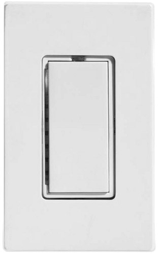
Figure 24-1: A PLC dimmer rocker switch
- DimmerA PLC dimmer works virtually the same as a manually operated dimmer, except that the dim/bright setting is activated through a signal transmitted over the PLC lines. Some models of dimmer switches allow for dim/bright control to happen at the switch. A common form of a PLC dimmer switch is a rocker switch where pressing the rocker down dims the lamp, as shown in Figure 24-1.
Photo courtesy of Smarthome, Inc.
- RelayA PLC relay is essentially an on-off switch that is used to complete or interrupt a power circuit to a device and is used to turn on or turn off a lamp.
- Plug-in modulesThis type of PLC module connects to the electrical wiring of a home through a room outlet by plugging into the electrical system like any other electrical appliance. The device you wish to control, such as a lamp or fan, is then plugged into the PLC module.
- DimmerPLC lamp modules that plug into an electrical outlet are used to provide dimmer control of table lamps and other lamps that can be plugged into an AC outlet on the module.
- RelayPLC appliance modules can be used to control the on/off functions of lamps and other electrical devices. They do not allow for dim/bright control. Figure 24-2 shows a PLC plug-in relay module.
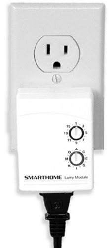
Figure 24-2: A PLC plug-in relay module can be used to control lamps and electrical appliances.
Photo courtesy of Smarthome, Inc.
- Hard-wired modulesThis type of PLC lighting control module is directly installed and connected to the AC wiring of a home.
- DimmerHard-wired PLC dimmers are switches that offer remote control of dim/bright/on/off of lighting. Figure 24-3 shows a hard-wired PLC dimmer control and Figure 24-4 shows a hard-wired PLC dimmer control installed in an outlet box.
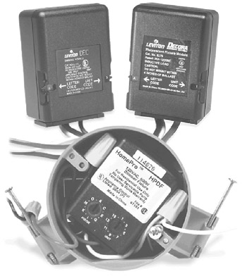
Figure 24-3: A PLC hard-wired lighting module that can be used to control dimming and on/off functions of a lamp/lighting load
- DimmerHard-wired PLC dimmers are switches that offer remote control of dim/bright/on/off of lighting. Figure 24-3 shows a hard-wired PLC dimmer control and Figure 24-4 shows a hard-wired PLC dimmer control installed in an outlet box.
Photo courtesy of Smarthome, Inc.
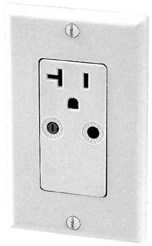
Figure 24-4: A PLC controlled outlet installed in an outlet box
Photo courtesy of Smarthome, Inc.
- RelayHard-wired PLC relay modules can be used to control the on/off functions of lamps and other electrical devices. They do not allow for dim/bright control.
- Controlled OutletHard-wired electrical receptacles offer either one or two PLC-enabled and remotely controlled AC outlets in a duplex device. Relay devices are also available that are installed directly into the AC system without the need to replace existing light switches. Figure 24-4 illustrates a controlled outlet.
- Control Devices
- Plug-in ControllerPLC plug-in interfaces and controllers can be used to control any device controlled by PLC such as switches, plug-in modules, hard-wired modules and controlled outlets.
- Wireless Handheld RemotePLC wireless remote controls use radio frequency (RF) signals to control both plug-in and hard-wired PLC modules. A handheld remote control communicates to a remote control transceiver module that is connected to the home’s AC lines by plugging into an outlet. It receives the RF signal and converts it to a PLC signal and sends the desired control command out over the electrical wiring.
- Wired Remote Control SwitchPLC control signals can be sent from hard-wired control switches that transmit PLC control commands. See Figure 24-5.
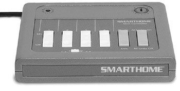
Figure 24-5: A PLC handheld remote control and plug-in wireless base unit
Photo courtesy of Smarthome, Inc.
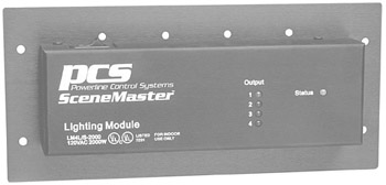
Figure 24-6: A PLC lighting controller unit
Photo courtesy of Smarthome, Inc.
- Wireless Remote SwitchMany PLC devices are remote control-enabled to allow the on/off and dimmer functions to be controlled remotely through a handheld or tabletop remote control.
- System ControllerPLC controllers are available that provide the capability to program control of the lighting in a single room, zone, or a whole house. Programming can usually be done to control several lighting loads at a time, by time of day, day of week, sunrise/sunset, or an input to the system.
Wired Lighting Control System Devices
A wired lighting control system can be a very simple affair, consisting of a local wall-mounted controller or it can be a very complex whole-house system that is integrated into a programmable controller. How a wired lighting control system works is that each lighting load is wired back to a control module that regulates the electrical power to the load. The following sections describe the various devices that may be used in a wired lighting control system, but the emphasis is on a more robust system.
The devices that can be used in a wired lighting control system are
- System controller
- System enclosure
- Modules
- Relay module
- Dimmer module
- Circuit breaker module
- Relay Input/Output module
- Control station
- Sensors
Lighting System Controller
Also referred to as the master unit or CPU, the system controller includes the microprocessor, clock, and operating memory of the lighting control system. A particular brand of lighting control system may require multiple controllers—one for each zone—or the system controller may be capable of controlling multiple zones. The system controller, see Figure 24-7, typically has a user interface that consists of a keypad (or keyboard) and display (small window or full size monitor) through which the controller is programmed, controlled, and diagnosed. Or the controller has the option for connection from a computer for downloading and uploading of programming.
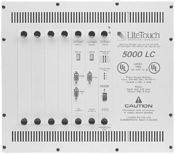
Figure 24-7: A lighting control system controller
Photo courtesy of LiteTouch, Inc.
Many lighting control systems are available with a complete control panel, like the one shown in Figure 24-7. These systems typically include all of the features required by an average-sized home, but in larger homes, the fully integrated control system may need to be assembled from a robust controller and optional modules and components to get the correct mix of device controllers, breakers, and power.
System Enclosure
Depending on the system, the enclosure cabinet will accommodate a varying number of control modules. The size of the enclosures and the quantity needed should be chosen based on the number of control modules to be placed inside the enclosures. The number of control modules is determined by the number and type of lighting loads to be controlled. Many models of enclosures are available to accommodate anywhere from one to six different lighting control or power modules and up to 48 relays or 30 dimmers, with some even larger. For example, the enclosure shown in Figure 24-8 can be configured with a large number of both relays and dimmer controls. Common features of lighting control enclosures are locking doors, internal venting fans, internal power supply, and optional flush-mounting kits.
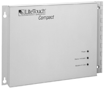
Figure 24-8: A compact lighting system central control unit can be outfitted with several dimmer and relay modules to control a whole-house lighting system.
Photo courtesy of LiteTouch, Inc.
Modules
Modules are installed inside the enclosures and lighting loads controlled are connected to the appropriate type of module. Power is fed to the enclosure and then to each of the modules and then on to the individual lighting loads. The type of lighting load determines the type of module needed. See Chapter 23 for detailed discussion on lighting load types.
Controlling Fluorescent Lamps
In many situations, switching controls are used to regulate fluorescent lamps. However, dimmable electronic fluorescent ballasts are available that allow the illumination produced by a fluorescent lamp to range from as low as two percent of its capability to a full 100 percent illumination.
Dimmable fluorescent ballasts vary in how much they are able to dim a fluorescent lamp. Ballasts are available with dimming ranges that range from 100 percent to less than 20 percent, less than 10 percent, less than 5 percent, and less than 1 percent. How much dimming is required by the lighting design will determine which dimmable ballast should be installed. One note though, as the dimming range increases, so does the cost of the ballast.
Relay Modules
Relay modules control the ON/OFF of a variety of loads including light fixtures, fans, proprietary two-wire and virtually all three-wire devices such as fluorescent, incandescent, and other types of low-voltage lighting.
Dimmer Modules
Dimmer modules control the ON/OFF/DIMMING of incandescent light fixtures. Some dimmer modules can handle certain types of low-voltage lighting.
Circuit Breaker Modules
Some lighting control systems offer controllable circuit breaker modules or panels (see Figure 24-9) that can be preset to provide circuit-level lighting control, such as security lighting, landscape or pool lighting, or other large lighting groups. In some systems, the breaker modules and panels can be networked to provide for additional zones under a common controller.
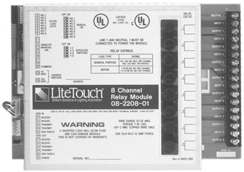
Figure 24-9: A relay module that is mounted in the central lighting control unit
Photo courtesy of LiteTouch, Inc.
Relay Input/Output Modules
Relay I/O modules are used on lighting control systems for low voltage input and output signals to and from the system controller. Examples of what might be on a relay input module include security system or a driveway probe. Examples of what might be on a relay output module include a motorized shade or garage door opener. Typically, the relay modules of a lighting control system can be interconnected on a common high-speed data link that allows them to share input and output among themselves and with the controller unit. In some systems, the relay modules have independent processors that allow them to function with or without the controller online.
Control Stations
Control stations, like the one shown in Figure 24-11, are placed in the individual rooms and allow the occupants to control the lighting loads/lamps in the room, or around the house, individually and by scene control. Since each of the control buttons is designed in programming, they can do simple ON/OFF control, dimming control (see Figure 24-10), scene control or can even be programmed to control outside systems connected to the lighting control system such as a whole-house music system. Many manufacturers offer custom engraving on the lighting control’s buttons to mark each button with the scene or zone it controls.
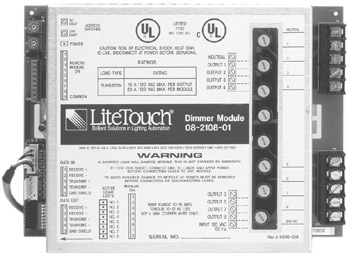
Figure 24-10: A dimmer control module
Photo courtesy of LiteTouch, Inc.
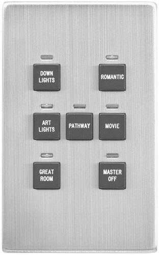
Figure 24-11: A multifunction remote station lighting control unit
Photo courtesy of LiteTouch, Inc.
Sensors
In addition to control stations and remote controls placed in a room or zone, the lighting control system can also include sensors that detect occupancy and daylight levels. The sensors used for this purpose are
- Motion or occupancy detectorThis type of detector senses when someone enters a room or when there is movement or activity within its scanning range. The two types of motion or occupancy detectors are
- Passive IR (PIR)PIR sensors detect changes in the energy radiating from occupants in a room. Like all IR sensors, PIR sensors require a line of sight to work properly. Typically, one or more sensors are placed in a room to encompass its doorway and the primary activity areas.
- Active ultrasonicUltrasonic sensors work something like sound wave radar. The sensor emits a high-frequency sound wave that is reflected off of an object in the room. Movement in the room changes the frequency of the reflected sound wave, which is interpreted as somebody entering the monitored space. A signal is transmitted to the controller, which then turns on the lights.
There are sensors available that incorporate both PIR and ultrasonic technologies to detect occupancy or movement in a space. Most have settings that can be adjusted to ignore pets or vibrations produced by the HVAC system.
- Photo sensorsThis type of sensor detects the level of natural light in a room or zone. Typically, a photo sensor is used to detect the need for additional artificial light to augment natural daylight to maintain a certain level of lighting in a space.
Wireless Lighting Control System Devices
A wireless lighting control system can be a very simple affair, consisting of a small wall-mounted controller or it can be a very complex whole-house system that integrates remote wireless switches and control devices into a programmable controller. The following sections describe the various devices that may be used in a wireless lighting control system.
The devices that can be used in a wireless lighting control system are
- System controllerThe system control unit is essentially the same type of unit as is used in a hard-wired system with the exception of wireless RF communications that allow the system to receive and send signals for control anywhere inside or nearby the exterior of the home.
- Wireless switchesWireless lighting system switches are hard-wired to the electrical and can be operated either locally or remotely using RF signals. They transmit and receive signals via RF to/from a base station or the system controller. They should not be confused with PLC wireless remote control switches. Wireless lighting system switches, like those of a hard-wired or PLC system are either dimmers or relay-type controls.
- Dimmer switchesWireless dimmer controls are either a part of a whole-house wireless lighting system or they can be stand-alone devices that control only one or two individual lamps. Stand-alone wireless dimmers require a receiver unit be installed in the lamps to be controlled by the dimmer; when the dimmer is operated manually, it transmits an RF signal to the lamp receiver that dims or brightens the lamp.
- Relay switchesLike other relay light switches, a wireless relay switch (see Figure 24-12) controls the on/off functions of a lighting load/lamp. Like wireless dimmer switches, there are devices that are intended for use as a part of a whole-house system and stand-alone devices, which require a receiver to be installed on the lamp.
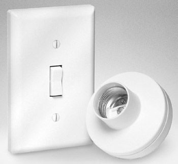
Figure 24-12: A wireless relay switch and lamp receiver
Photo courtesy of Smarthome, Inc.
- Remote control stationTypically, a wireless lighting system station, which provides the same functions as hard-wired control stations, also serves as a signal extender to ensure the signal strength throughout a home.
- SensorsWireless occupancy sensors or motion detectors transmit their event or alarm signals using RF transmission rather than requiring hard-wired connections.
Programming Control Options
The most powerful benefit of a lighting control system is the extensive automated or logical control that can be programmed, including scheduling, scenes, and what-if situations. Programming can enhance the simple control, safety, security, and energy savings of a home.
Scheduling Programming
A scheduling program turns lighting on, off, down, or up based on a preset daily time schedule or day of the week or calendar date. This approach to lighting control is intended to avoid lighting areas during daylight hours or during periods when a home is not occupied. In many systems, each zone can be programmed with a different lighting schedule according to the lighting needs of the homeowners. The program can often be set up to know the latitude and longitude of the location and so figure out sunrise and sunset and then schedules can be made based on this information such as landscape lights on at sunset.
Scenes
Virtually all lighting control systems have the ability to control a number of different lighting scenes, often in more than one lighting zone. Creating a preset lighting scene, which the press of a single button on a local control station, will ultimately activate, involves first and foremost some detail planning.
Depending on the lighting control system in use, a lighting scene is created with either a top-down or a bottom-up approach. In the top-down approach, the lighting scene function, such as “movie,” is created first. Then the lighting devices to be controlled in the scene are added and finally the dimmer level of each lighting fixture included in the scene is set, typically as a percentage of its maximum lighting level. In a bottom-up approach, the various lighting levels for each lighting device are created and given some form of an identity, such as “ceiling lights—50%,” “sconces—25%,” or “lamps—10%.” This creates a sort of menu from which the lighting events desired for a particular scene can be added together to create the scene.
What-if Situations
Based on input, lighting control commands are executed in what-if situations. The input can be from known information such as “Security System in NIGHTTIME mode.” An example would be “If Security armed in NIGHTIME, landscape lights OFF.” What-if questions can be combined to have complex decisions made regarding lighting control. These compound what-if questions are a form of Boolean logic. An example would be “If dark AND security armed in Away Mode THEN turn on living room lights.” You would repeat this command with the same what-if question to have them turned off at 10:15 pm, or if it is Friday or Saturday, turn them off at 11:20 pm.
Occupancy Sensor Input for Lighting Control
When a sensor placed in a room or zone detects that someone has entered a room, a signal is sent to the lighting system controller and it takes the necessary action to turn the lighting on in that space. Occupancy control systems are more energy efficient because lighting is provided only when a room is occupied. If the sensor determines the room is not occupied or that there hasn’t been any activity in the room for a certain time, the controller can then turn off the lights. The type and placement of the sensor used is the key to how well this type of lighting control approach works.
Daylighting Sensor Input for Lighting Control
Daylighting sensors attempt to use the natural daylight in a room to determine the amount of artificial light that should be added to produce a certain preset amount of lighting in the room. Daylighting systems, which are also called daylight harvesting systems, can be used with either dimming or switching controls. However, the availability of dimming controls for fluorescent lamps has made this type of system very popular in commercial settings and more recently in homes.
Boolean Logic
In the 1800s, a mathematician by the name of George Boole developed a correlation between mathematics and logic called Boolean algebra, which is based on combinations of true and false or on or off conditions.
Boolean algebra, which is more commonly referred to as Boolean logic these days, is the mathematical principles used in computer logic. Boolean logic creates logical relationships between entities using three primary comparison operators (OR, AND, and NOT) to determine if a logical comparison is true or false.
The OR operator returns true if any entity in a set meets the conditions of the logical comparison. For example, if the conditional test of “Is a Girl” is applied to a set of children made up of two boys and one girl, the result is true because one entity in the set actually is a girl. The fact that two of the children are boys is irrelevant and because the girl is a girl the set satisfies the test, which is applied sort of like “if this one is a girl, or that one is a girl, or the other one is a girl,” then Is a Girl is true. In a lighting situation, the test might actually be something like, “If Night OR Morning, then …” This test would return true if either of the preset values Night or Morning were true themselves.
The Boolean AND operator tests for all entities of a set meeting a logical condition. If we were to apply the test of “Is a Girl” to the same group of children (two boys and one girl) using the AND operator, the result would be false. In order to satisfy the conditions of the test, all three of the children would have to be girls. This test is applied as “if this one is a girl, and that one is a girl, and the other one is a girl, then Is a Girl is true, otherwise Is a Girl is false. An example of how the AND operator is used in a lighting control program might be something like, “if DayLight AND < 1700, then …” In this case, if the variable DayLight is true and it's earlier than 5:00 pm, then the test returns a true and performs whatever action is indicated by the “then” statement.
The Boolean NOT operator reverses the test by being true only if the result is false. Huh? Okay, bear with me on this one. If we test for “Is NOT a Girl” on each of the children, we would get two trues and one false. As convoluted as it may sound, when this test is applied to the children, we are actually testing for “Is a Boy,” because the NOT operator reverses the test. So, when we test “Is NOT a Girl” on a boy, the result is true because he is not a girl. An example of how this could be used in a lighting program is “If NOT Activated, then …,” which would return true only when the system is not activated.
Without becoming too complicated, Boolean NOT logic also can be used to reverse OR and AND comparisons as well. For example,” NOT Girl OR Boy” would return a true only if all of the children were girls or boys, which is effectively the same as testing “Girl AND Boy.” In the same way, “NOT Girl AND Boy” returns a true if the set includes both girls and boys—or the equivalent of “Girl OR Boy.” As you can see, NOT logic is probably best used when testing a single value.
Daylighting systems use photoelectric sensors to detect the lighting level in a room or space. When the lighting is too high, the controller dims or turns off light fixtures to lower the ambient light. When the lighting is too low, the controller turns on or up the lighting in the room to bring the light up to the desired level. In a large area, more than one sensor may be required to prevent uneven lighting.
Lighting System Standards and Guidelines
A licensed electrician must perform electrical work. You need to work with the project electrician on the layout and installation of the lighting control system. Remember to plan for electrical power for the controller and discuss if a generator will be in the home and if yes, what lighting loads (and the system controller) should be on it. The wiring for the remote control stations is usually low voltage wiring and in most areas does not need to be done by a licensed electrician.
In any case, you should be aware of the national, state, and local electrical codes and regulations that apply to the installation of a lighting control system and any wiring required to support it.
NEC
The National Electric Code (NEC) is the generally accepted basis for almost all state and local electrical codes. However, some areas may exceed the requirements of the NEC and require higher quality materials or more stringent cable management requirements. Be sure to know what is practiced in your area.
The general requirement by the NEC is for a minimum of 14 AWG circuit wiring protected by a 15-amp circuit breaker or fuse. There are some exceptions to this requirement, such as the wiring for doorbells and a few other low-voltage systems, but by and large, 14-gauge wiring is the standard. However, there is a trend in home construction to install 12-gauge wiring on 20-amp circuits, which has become a standard in some locales.
If given a choice, you should prefer the heavier 12-gauge wiring and the 20-amp circuit breaker. This larger wiring will provide the lighting system with brighter lights, better energy efficiency, and far fewer tripped circuit breakers or blown fuses.
Some other areas where the NEC has requirements that impact a lighting system are in the areas of the height (from the floor) for wall switches, outlets, and connectors and its specifications for acceptable light fixtures and switches. See Chapter 4 for more details on codes and Chapter 23 for more information on these requirements.
Chapters 4 and 5 of the NEC detail the requirements for low-voltage lighting systems (including lighting control systems), and particularly in Article 411 of the NEC. Residential lighting and lighting control systems come under the requirements specified in Article 411 and UL (Underwriters Laboratories) 2108 and the components installed in these systems must comply with the requirements of these regulations.
The primary issues to consider when installing a lighting control system to comply with the NEC regulations are that the lighting control panel must not be placed in close proximity of the home’s main electrical panel and any relays installed in the lighting control panel must be protected by a circuit breaker or fuse. Be sure that all components of the lighting control system conform to NEC Section 110-10 and Article 411 regulations and any applicable UL, CSA, or other fire safety testing authority guidelines. All elements of the total control system must be considered and be matched to the circuit and its over-current protection devices (circuit breakers or fuses). The NEC refers to this rating as a component short-circuit rating (SCCR). Remember that if any one component in the entire system doesn’t comply with the applicable regulations, the entire system is not in compliance.
Installation Safety
Your safety and that of your customer are the intent of the NEC and the other electrical and fire safety regulations that govern the components and installation of lighting control systems. To ensure a safe and effective installation, here are some guidelines you should follow:
- Ensure that all devices to be installed are matched to the voltage level of the circuit to which they are to be attached.
- Turn off the power supply of the control system and turn off the electrical supply on its circuit and the main electrical panel before you begin installation.
- Test all newly installed wiring for continuity prior to connecting it into the lighting control panel.
Completing the Installation
The following steps should be used to complete the installation of a lighting control system:
- Power up system control panel, following the manufacturer’s instructions.
- Install all local control devices and test locally room by room.
- Test remote control devices.
- Program preset lighting scenes and set local station functions. Test all scene settings to ensure they are properly set.
- If scheduling and what-if situations programming are in use, test and observe these functions during complete cycles.
Review
PLC lighting control uses the electrical wiring to send command signals to control switches and devices. In X-10 technology, each device is coded by a letter (A-P) and a number (1-16). The PLC devices typically used are switches, plug-in modules, hard-wired modules, and control devices.
A hard-wired lighting control system can consisting of local wall-mounted controllers or be a whole-house system integrated into a programmable controller. How a wired lighting control system works is that each lighting load is wired back to a control module that regulates the electrical power to the load. The devices that can be included in hard-wired lighting system are a system controller, several types of special purpose modules, remote stations, and sensors.
The lighting system controller includes the microprocessor, clock, and operating memory. Multi-zone systems may have a single controller or require multiple controllers. The system controller typically has a user interface that consists of a keypad or keyboard and a display. The various types of lighting control modules that can be installed in a wired lighting control system include relay modules, dimmer modules, circuit breaker modules, and relay I/O modules.
Control stations in the individual rooms allow occupants to control the lighting loads/lamps in the room, or around the house, individually and by scene control. In addition to simple ON/OFF and dimming control, some control stations can be programmed to control outside systems.
Sensors can be used to detect occupancy and daylight levels. The sensors used for this purpose are motion or occupancy detectors and photo sensors.
A wireless lighting control system provides the same functionality as PLC and hard-wired systems, with the exception that the control of the lighting control switches and devices is by RF communications. The devices used in a wireless lighting control system, include system controllers, wireless control switches, relay modules, remote stations, and sensors.
The most powerful benefit of a lighting control system is the extensive automated or logical control that can be programmed to provide scheduling, lighting scenes, and what-if situations. Scheduling programs turn lighting on, off, down, or up using a preset time or day schedule. Programmed lighting control commands are executed in what-if situations, where time, day, and sensor inputs are tested to determine the activation of certain lighting scenes.
A licensed electrician must perform electrical work. Work with the project electrician on the layout and installation of the lighting control system. You should plan for electrical power for the controller and, if a generator is part of the electrical system, which lighting loads and devices should be on it. You should be aware of the national, state, and local electrical codes and regulations that apply to the installation of a lighting control system and any wiring required.
The National Electric Code (NEC) is the generally accepted basis for almost all state and local electrical codes. Some areas may exceed the requirements of the NEC and require higher quality materials or more stringent cable management requirements. The general requirement by the NEC is for a minimum of 14 AWG circuit wiring protected by a 15-amp circuit breaker or fuse. Residential lighting and lighting control systems are specified in NEC Article 411 and UL (Underwriters Laboratories) 2108.
To ensure a safe and effective installation: ensure that all devices to be installed are matched to the voltage level of the circuit where they are to be attached; turn off the power supply of the control system and turn off the electrical supply on its circuit and the main electrical panel before you begin installation; and test all newly installed wiring for continuity prior to connecting it into the lighting control panel.
Questions
- What two types of lighting controls are generally used in most residential lighting control systems?
- Dimming
- Inductive
- Photo cell
- Switching
- What is the type of lighting control that has the ability to range the amount of light emitted by a lamp from off to the lamp’s full capability?
- Dimming
- Inductive
- Photo cell
- Switching
- True or False: A switching control has the ability to lower a lamp to 50 percent of its lighting capability.
- True
- False
- What type of lighting control sensor involves the use of IR sensors?
- Daylighting
- Occupant-sensing
- Scheduling
- Preset
- What type of technology uses AC power lines to transmit lighting control system signals?
- Bus
- Data networking
- Wireless
- PLC
- What type of lighting control system uses motion detectors placed in certain areas to turn on or off the lighting in an area?
- Scheduling
- Occupant-sensing
- Daylighting
- Exterior
- What type of lighting control system uses artificial lighting to enhance the natural lighting in a room or zone?
- Scheduling
- Occupant-sensing
- Daylighting
- Exterior
- What device is the primary unit of a lighting control system?
- Remote station
- Relay module
- Breaker module
- System controller
- Which part of the NEC specifies the requirements for lighting control systems?
- Article 411
- Section 110-10
- UL 2108
- SCCR
- What communications technology do wireless lighting control systems use?
- IR
- PLC
- RF
- HomePNA
Answers
- A and D. Lighting control systems have the option of either dimming the lamp of a fixture or switching it on or off.
- A. The only other choice available that makes any sense at all is switching, and it has only on or off settings.
- B (False). Switching controls are all or nothing devices.
- B. Motion or occupancy detectors are used to turn on the lighting of a room when a room is occupied or someone enters the room.
- D. PLC technology is implemented as either X-10 or CEBus. The other choices do not apply in this case.
- B. Scheduling systems use preset time schedules and daylighting use photocells to determine the level of daylight in a room. Exterior systems may use any motion detectors to turn on lighting, but they then become occupant-sensing systems as well.
- C. Photocells are used to enhance the daylight or natural lighting of a room to maintain certain lighting levels.
- D. The other choices are optional devices in any lighting control system, but the system needs a controller unit.
- A. Actually, NEC Chapters 4 and 5 are the general references, but Article 411 is specific to lighting controls.
- C. You may see some PLC systems referred to as “wireless,” but in their case, the wireless refers to either “no-new-wires” or the use of an IR remote control to activate a dimmer or control module.
Part I - Home Technology Installation Basics
- Wire and Cable Basics
- Connector Types and Uses
- Wiring Installation Practices
- Codes, Standards, and Safety Practices
Part II - Structured Wiring
- Infrastructure Wiring Basics
- Planning a Structured Wiring Installation
- Rough-In Installation
- Trim-Out Installation
- Troubleshooting Structured Wiring
Part III - Home Computer Networks
- Computer Network Basics
- Computer Network Hardware
- Computer Network Software
- Designing and Installing a Computer Network
- Troubleshooting a Home Network
Part IV - Audio/Video Systems
- Distributed Audio System Basics
- Designing and Installing Distributed Audio Systems
- Distributed Video Basics
- Designing and Installing Distributed Video Systems
- Troubleshooting Audio Systems
- Troubleshooting Video Systems
Part V. Home Lighting Management Systems
- Home Lighting Basics
- Home Lighting Devices
- Designing a Home Lighting Control System
- Installing a Home Lighting Control System
- Troubleshooting and Maintaining Lighting Control Systems
Part VI - Telecommunications
- Home Communication System Basics
- Designing and Installing a Home Telephone System
- Troubleshooting a Home Communication System
Part VII - HVAC and Water Management
Part VIII - Security System Basics
- Security System Basics
- Designing a Home Security System
- Installing a Home Security System
- Troubleshooting and Maintaining a Home Security System
- Home Security Surveillance Systems
- Home Access Control Systems
Part IX - Home Technology Integration
- Defining Users Needs and Desires
- User Interfaces
- Home Automation Controllers
- Programming
- Integrating the Connected Home
- Other Home Technology Integration Devices
Part X - Appendices
EAN: N/A
Pages: 300
