Distributed Video Basics
Distributed VideoBasics
In this chapter, you will learn about
- Video signal transmissions
- Video standards
- Internet media
- Televisions and video monitors
- Personal video recorders (PVRs)
- Media servers
One of the truly daunting parts of writing a book on technology, let alone an emerging technology such as home audio video (AV), is that the technologies included are changing as fast as this book is written. Okay, it may not be as bad as that, but home AV technologies are fast moving targets. So, this chapter takes a look at some of the currently available AV recording, storage, and distribution devices.
Much of the material in this chapter is background information. However, that doesn’t mean you don’t need to know it. In fact, if you are new to distributed video, it is recommended that you read this chapter.
Transmitting Video Signals
Video signals are broadcast in either an analog or a digital format. Analog signals are broadcast through the air and received by a home’s TV antenna. However, analog signals can also be transmitted to a home over a cable system. Digital video signals are typically not broadcast but transmitted over a cable system between a source device and a video display device. High-definition television (HDTV) is the closest an on-air analog broadcast system comes to reproducing the quality of a digital video signal because HDTV transmits a signal with more lines of resolution than the standard analog broadcast.
Analog video signals are radio frequency (RF) signals regardless of whether they are transmitted through the air or carried on a cable system. Broadcast, or “over the air,” video signals are limited to licensed broadcasters, who are typically VHS broadcasters licensed by the Federal Communications Commission (FCC) to do so. Unlicensed, or “cable,” operators transmit their video signals using dedicated broadcasting methods, such as microwave and cable transmissions.
Baseband Versus Broadband
There are two basic types of transmitted radio frequency (RF) signal formats used to carry video signals: baseband and broadband.
Baseband
Baseband communications use the entire transmission medium to carry a single frequency or composite signal in original, unmodulated form. There are three types of baseband signals:
- CompositeThis signal format transmits the complete video signal, including its picture (luminance), color (chrominance), and signal-blanking and synchronization pulses.
- ComponentThis signal format uses three conductors to carry five separate frequency bands (one each for red, green, and blue, also know as RGB, and one each for luminance and chrominance. Component baseband is rarely used, except in very high-end video systems.
- S-VideoThis signal format, which is also known as Y/C video, super video, and separate video, transmits the luminance and chrominance signals separately, which improves the picture clarity. The Y (luminance) signal carries the brightness information and the C (chrominance) signal carries the color information.
Two baseband cables are required to transmit the video and audio source signals in a television broadcast. Figure 17-1 illustrates how broadband RF signals are received by an antennae and passed to a TV receiver, which splits the audio and video into separate baseband signals for other devices.
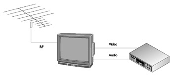
Figure 17-1: On-air baseband TV reception
Broadband
Broadband communications transmit multiple signals using a separate frequency for each one. The most common broadband video system is the cable television system, which transmits its broadband RF signals over coaxial cable. Broadband coaxial cable, which is commonly referred to as Community Access Television (CATV), is capable of transmitting 130 analog (RF) channel transmissions, and in some cases even more. Table 17-1 lists the standard channel allocations for broadband RF. Each channel carries both the audio and video signals of the transmission.
|
Band |
Frequencies |
Broadcast Channels |
CATV (Cable) Channels |
|---|---|---|---|
|
Very High Frequency (VHF) Low Band |
54 – 84 MHz |
2 – 6 |
2 – 6 |
|
Frequency Modulation (FM) Radio |
88 – 108 MHz |
||
|
CATV Mid Band |
120 – 170 MHz |
14 – 22 |
|
|
VHF High Band |
174 – 212 MHz |
7 – 13 |
7 – 13 |
|
CATV Super Band |
216 – 296 MHz |
23 – 36 |
|
|
CATV Hyper Band |
300 – 468 MHz |
37 – 64 |
|
|
CATV Extended Hyper Band |
468 – 820 MHz |
65 - 121 |
|
|
Ultra High Frequency (UHF) Band |
470 – 806 MHz |
14 – 69 |
Modulation
The video device used to convert baseband to RF (broadband) signals is a modulator (more on modulators and other video devices later in the chapter). However, not all video signals require modulation. The analog video signals received by a home antenna and those transmitted over cable television service are RF signals and don’t required modulation for transmission or playback.
Two objectives must be designed into the cabling (typically coaxial cabling) used to carry RF signals in a home’s distributed video system: the signal strength must be sufficient to provide a quality signal to the display or playback device, and that radio and electrical interference must be minimized or eliminated. The best way to make these assurances in a video distribution signal is through the use of high-quality RG6 cable and connectors.
Video cabling is only able to transmit RF signals from point A to point B. They cannot be used in parallel to transmit signals in a one-to-many arrangement because the receiving end of the cable expects to receive only a single 75-ohm signal. In situations where a single RF video source is to be transmitted to more than one end device, a splitter (see Figure 17-2) must be used. A splitter is a device that takes in a single 75-ohm RF signal and outputs two or more separate 75-ohm signals. The most common type of splitter used is a passive splitter, which does nothing to enhance the strength of the split signals.
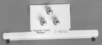
Figure 17-2: A one-line to two-line RF cable splitter with a distribution center mounting
Photo courtesy of Channel Vision.
Another RF signal device that can be used in a distributed video system is a combiner, which is, in effect, the mirror opposite of a splitter. A combiner combines two (or more) incoming RF signals into a single combined broadband signal, as long as the two incoming signal lines don’t share any common channels. A combiner can be used to combine cable television service with the signals from a digital satellite system passed through a modulator to change their channel modulations so there is no overlap with the cable channels.
Video Signal Loss
As the video signal is distributed throughout a home’s video system, the signal strength suffers loss (meaning a loss of signal strength) as it passes through splitters, combiners, and connectors. As a result, the signal strength that reaches the display device may not be sufficient to provide a quality picture or sound, especially on systems where the video signal is being distributed to multiple displays.
| Note |
Video signal strength is measured in decibels ( dB), and most televisions require a signal between 0 dB and 12 dB, although most will operate with -4 dB to 15 dB. |
To maximize signal strength, focus the antenna or satellite by using either a compass to point it in the appropriate direction of the broadcast source or the signal strength indicator that is sometimes built into the receiver. If you are not sure of the provider’s transmission location, give them a telephone call.
For a strong enough signal where no amplifier is required you must have 0 dB signal off of an off-air antenna (ultra high frequency, or UHF, and very high frequency , or VHF). The digital satellite signal (DSS) level should be between -55 dB and -35 dB. Always use 75-ohm resistor terminators at any unused jack to prevent signals from traveling back up the line and causing ghosts. If direct current (DC) power or infrared (IR) signals are being sent over coaxial cable, use a DC blocking capacitor.
There are several places on a video line where signal loss can occur, but the most significant locations are:
- ConnectorsSignal is lost wherever a connection is made. This is where most signal strength is lost in a typical residence.
- WiringSignal is lost as it travels through the coaxial cable. This loss is dependent on the length of the wire (the average is 3 dB to 6 dB of signal loss per 100 feet), the type of wire, and the frequency of the signal being carried. Losses are greater at higher frequencies; the greatest loss occurs at channel 13 in a VHF system or channel 83 in a UHF/VHF system.
- SplittersLine splitters split the signal into two, three, four, or eight separate lines. Splitters divide the input signal equally, providing the same amount of signal at each output of the splitter. When a splitter is inserted in the line, the signal in each branch leg will be less. The quality of the splitter used does have an impact on the amount of loss incurred with the splitter. The losses that occur with average quality splitters are:
- Two-way splitter3.5 to 4 dB loss
- Three-way splitter3.5 dB loss
- Four-way splitter6.5 to 8 dB loss
- Eight-way splitter10 to 12 dB loss
The signal sent to each branch of the system is equal to the signal sent into the splitter minus the loss induced by the splitter. For example, an input of 30 dB into a three-way splitter delivers a signal of 26.5 dB to each branch of the system (30 dB minus a 3.5 dB loss).
Figure 17-3 illustrates this phenomenon. As illustrated, the incoming video line signal has signal strength of 15 dBmV (decibels per millivolt on a 75-ohm line). Each splitter or combiner device through which the signal passes causes signal loss in varying amounts (see Table 17-2). In Figure 17-3, an 8-way splitter causes a loss of -12 dBmV, reducing the signal to only 3 dBmV. A cable run of 100 feet introduces additional loss of -4 dBmV, leaving the cable with a negative gain or virtually no signal strength.
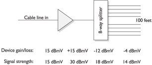
Figure 17-3: Signal loss on a video distribution system
|
Device |
General Signal Loss |
|---|---|
|
2-way splitter/combiner |
-4.0 dBmV |
|
3-way splitter/combiner |
-6.5 dBmV |
|
4-way splitter/combiner |
-8.0 dBmV |
|
8-way splitter/combiner |
-12.0 dBmV |
|
100 feet RG6 cable |
-4.0 dBmV |
Signal loss can also be caused by the length of the cable over which it is transmitted. Table 17-3 lists the common signal loss (measured in decibels per each 100 feet of cable length) on the two standard coaxial cable types used in residential video systems.
|
Frequency |
RG59 |
RG6 |
|---|---|---|
|
55 MHz |
2.06 dB |
1.60 dB |
|
270 MHz |
4.47 dB |
3.50 dB |
|
400 MHz |
5.48 dB |
4.30 dB |
|
750 MHz |
7.62 dB |
6 dB |
|
1 GHz |
8.87 dB |
7 dB |
Amplification
To overcome the loss of signal on the distributed video line, an amplifier should be added to the system. The purpose of the amplifier is to add sufficient gain to the signal to compensate for the signal loss on the line. Amplifiers also stop signals from radiating outside the house. To properly size an amplifier, the amount of loss accumulated on the distributed line must be added up (per the specifications of each device).
When choosing an amplifier, the four main considerations are the frequencies and number of channels to be received; the total distribution system losses (the losses caused by cable, splitters, and connectors); available input signals (the signal levels fed to the distribution amplifier input); and the output capability of the distribution amplifier (the maximum signal the amplifier can deliver without overloading). An amplifier has three primary inputs and outputs:
- Input levelThe video signal coming in
- GainThe amplification of the video signal
- Output levelThe video signal going out
Remember that the amplification of the input signal plus any gain added to the signal equals the signal strength of the output signal. The “input plus gain” of a signal needs to be greater than the total loss the signal suffers on the distribution system. However, the output level of the signal can never be greater than the output capability of the amplifier. Some amplifiers have a variable gain adjustment, which can be very useful in some applications. An attenuator/tilt compensator may need to be added to decrease the amplification of the lower frequency signals that are amplified much easier than the higher frequencies. Also, the FCC limits a signal to no more than 15.5 dBmv at any outlet.
In most installations, an isolation amplifier can be used to provide enough gain to compensate for the loss suffered by signals as they travel through the cabling and devices of a distributed audio system.. As illustrated in Figure 17-4, an isolation amplifier (labeled “AMP”) is installed on the primary antenna or cable input line. This amplifier increases the gain on the line sufficiently high enough to withstand the loss introduced by the devices between it and the terminal device. However, an isolation amplifier is rarely needed, though in situations where the incoming signal is too weak to withstand passes through the distribution devices without additional amplification, it is an easy solution to the problem.
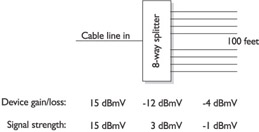
Figure 17-4: An amplifier is added to the video circuit to overcome signal loss.
Another approach, and a more common solution, is the inclusion of a main system amplifier in the video distribution system. An amplifier with a variable output level (gain) is best, but a fixed output amplifier can be used, if it is able to provide sufficient gain to offset any loss in incoming signals. The amount of gain required from an amplifier is calculated by adding up the signal loss on the input side (before the amplifier) to the loss on the output side (after the amplifier).
An amplifier only converts an incoming signal, regardless of its source, into a signal that has increased amplitude, or signal strength, to ensure delivery and quality playback on any connected devices. Most common amplifiers have the capability to increase the gain (volume) potential of a signal from 0 MHz to 400 MHz, with somewhere around 100 MHz as typical.
Gain refers to the percentage of signal strength or performance when the input signal is compared to an amplifier’s output signal. There are actually two types of gain associated with video systems. The first is the amplification of the audio signal that accompanies a video signal, which increases the volume potential for the playback. The second type of video gain refers to how much light (projected image) is reflected by a projection screen. As a screen is able to reflect more light, it produces a better quality image.
Receivers
Many systems combine the functions of an amplifier and a receiver, but these two devices perform completely separate functions. Most video receivers have an amplifier built-in. Very high-end systems may choose to use a separate amplifier, claiming that the receiver’s circuitry can add noise in the form of a buzzing sound to the audio. However, this is true only on the very low-end units. Good quality receivers, not necessarily the most expensive ones, don’t have this problem.
A receiver is an AV device that receives signals that are broadcast through the air and converts them to a form for viewing or listening presentation. There are receivers designed to receive and convert radio, satellite, cable, or microwave transmissions. A video receiver in its most common form is an ordinary television set and includes a complete AV system with a receiver, an amplifier, speakers, a display screen, an antenna, a tuning control, and volume controls.
An AV receiver is essentially an audio device that is included in a system to receive, convert, and coordinate the audio part of video playback. However, it should include support for all of the audio and video inputs that are planned to be used (and then some) and have the capability to pass video signals directly to a video display device.
Video Signal Formats
There are a variety of video signal formats in use in video distribution systems as well as on computers. The primary video signal formats are: RGB, component, S-Video, and composite.
Video signals are either optical or electronic. Optical signals originate from a camera or a scanner, and electronic signals originate from a computer’s graphics card. Regardless of how a video signal originates, it is made up of electric impulses that represent the intensity of each of three primary colors—red, green, and blue (RGB)—and the vertical and horizontal synchronization of each picture frame.
The RGB encoding tells the display mechanism at the receiving end how to re-create each picture element (pixel) of the original image. It is assumed that the final image has red, green, or blue colors in it. The video signal indicates how much, or the intensity, of each color used in each pixel. The intensity of each of these three colors, when combined by the human eye, determines the final color displayed.
If you look at the display of your television set, assuming it has a Cathode Ray Tube (CRT)—more on this later in the section “Video Screen Formats”—using a magnifying glass, you should see either a dot pattern or a pattern of lines. In either of these display methods, an electron beam is used to energize colored phosphor, which coats the glass on the face of the CRT’s tube either in patterns of dots or stripes.
Processing Video Signals
Regardless of the method used to create the display on the CRT, how the signal is processed, stored, or transmitted can have more to do with the quality of the displayed picture than the capability of the display device itself.
Table 17-4 lists the most common of the video signal formats in use.
|
Signal Format |
Description |
|---|---|
|
RGBHV |
RGB with Horizontal and Vertical sync. |
|
RGBS (RGB) |
RGB with composite sync |
|
RGsB (SoG) |
Aka Sync on Green, RGB with a sync signal sent on the green single, like composite video. |
|
YCrCb |
Component video, a black and white composite video signal that includes Luminance (Y) brightness information and composite sync, and two signals that carry matrixed color information (Chrominance) for Red and Blue (Cr and Cb) that can be removed from the Y signal to yield the green information. |
|
S-Video (Y-C) |
Black and white composite video that contains Y brightness and composite sync information. The composite C (chrominance) contains all of the color information. S-Video is also referred to as SVHS. |
|
Composite video |
The one composite video signal contains all of the information on brightness, color, and synchronization. |
|
TV/CATV |
Composite video and audio modulated to allow multiple signals to share a common transmission medium, such as terrestrial aerial, cable TV, or satellite. |
| Note |
You may have noticed that Red/Green/Blue (RGB) is not listed in Table 17-4. RGB is not a video standard. It is a standard for computer monitors. |
To combine the color information and the brightness and synchronization (timing) information, both must be coded. There are three primary coding schemes, also referred to as broadcast standards, in use:
- National Television System Committee (NTSC)The NTSC developed the first color television coding system in 1953. It uses a fixed resolution of 525 horizontal lines and a variable number of vertical lines, depending on the electronics or format in use. NTSC displays 30 frames per second. NTSC is also a type of television signal that can be recorded by various tape recording formats, including VHS, 3/4-inch, and U-matic.
- Phase Alternation by Line (PAL)This European improvement over NTSC was released in 1967. PAL uses 625 horizontal lines, which also make up its vertical resolution. It produces a more consistent tint, but at 25 frames per second.
- Systeme Electronique Couleur Avec Memoire (SECAM)This encoding method was introduced in France in 1967 and, like PAL, uses 625 lines of resolution and displays 25 frames per second.
These three-color encoding standards are incompatible with one another. However, most modern television sets are multistandard and can decode a video signal encoded with any of these schemes. Table 17-5 provides a sampling of the countries using these three-color standards.
|
Country |
Encoding Standard |
|---|---|
|
Canada |
NTSC |
|
Chile |
NTSC |
|
China |
PAL |
|
Egypt |
SECAM |
|
France |
SECAM |
|
Japan |
NTSC |
|
Mexico |
NTSC |
|
Russia |
SECAM |
|
United Kingdom |
PAL |
|
USA |
NTSC |
The most common of the video signal formats in use is S-Video. Virtually all AV amplifiers support S-Video, but only a few include higher-level formats such as component or RGBHV. If higher-level signal formats are all that is available, the signal can be converted to a lower-level signal for one or more devices. For example, an incoming RGB signal can be converted to S-Video for distribution throughout a home. Remember that there is no advantage or picture quality improvements gained by converting a signal to a higher-level format such as S-Video to RGB.
Television Video Formats
When the primary video types and broadcast standards are applied to the primary television formats, a variety of speeds, resolutions, and tape and disc record times result. Table 17-6 lists the various television, tape, and disc formats available.
|
Format |
Broadcast Standard |
Max Time (Minutes) |
Media |
|---|---|---|---|
|
VHS |
NTSC PAL SECAM |
480 600 600 |
T-160 E-300 E-300 |
|
SuperVHS |
NTSC PAL |
480 480 |
ST-160 SE-240 |
|
Digital VHS (D-VHS) and Digital Video Computing (DVC) |
NTSC PAL |
60 180 |
MiniDV cassette DVC |
|
Video 8 |
NTSC PAL |
240 180 |
P6-120 P5-90 |
|
Hi-8 |
SECAM NTSC PAL |
180 240 180 |
P5-90 P6-120ME P5-90ME |
|
LaserDisc |
NTSC PAL |
60 72 |
Constant Linear Velocity (CLV) CLV |
|
DVD |
NTSC |
Varies |
Dual Layer (8.6 GB) |
Distributed Video Terminology
The following list includes the more important video system terms you should know when specifying, selecting, and interfacing with video systems:
- Interface scanA display format where the displayed image is separated into two passes: the first pass scans the odd-numbered horizontal lines (1, 3, 5, and so on) and the second pass scans the even-numbered lines.
- Progressive scanA display format that displays each horizontal lines of an image in a single pass at typically 24, 30, or 60 frames per second (fps).
- National Television Standards Committee (NTSC)The signal format used to broadcast standard (non-HDTV) television.
- Standard Definition Television (SDTV)The standard interlace scan TV display using 460 by 480 pixels. Also referred to as 480i.
- Advanced Television Standards Committee (ATSC)The signal format used to broadcast HDTV.
- Enhanced Definition Television (EDTV)A progressive scan format that supports 460 by 480 pixels (standard TV) and 720 by 480 pixels (widescreen). Also referred to as 480p (480 vertical lines using progressive scan) and 720p.
- High Definition Television (HDTV)A display format that supports either 1280 by 720 pixels for progressive scan or 1920 by 1080 pixels for interlace scan. Also referred to as 1080i and 8-level Vestigial Sideband( 8-VSB), which is the radio frequency broadcasting format used for HDTV.
- ATSC (Advanced Television Standards Committee)The signal format used to broadcast HDTV.
Common Video Signals
For a home theatre installation, the video receiver should support the three primary video signal formats: component video, S-Video, and composite video. However, it is not common for an audio receiver to include jacks for all three input types. Sometimes there is a problem in that a receiver that does support these three signals may not include support for HDTV or progressive scan digital versatile disc or digital video disk (DVD) signals.
HDTV and Digital TVHDTV is one of the digital television standards defined by the ATSC. Digital TV (DTV) transmits using binary data (using positive and negative electrical impulses to represent ones and zeroes, just like a computer uses) to encode its images and audio. Standard analog TV signals use waveforms, frequencies, and amplitudes to transmit images and audio. In addition to the actual images and audio, the digital data of the DTV signal includes information that defines the resolution, aspect ratio, refresh rate (how often the image is scanned), and the type of scanning in use (interface versus progressive).
HDTV can be delivered to a home using one of the following four methods:
- Broadcast digital satelliteCompanies like the DISH Network and DIRECTV offer HDTV to customers that have upgraded their satellite dishes and receivers for DTV signals. The satellite dish needs to be a dual-Low Noise Block Feedhorn (LNBF) to receive both HDTV and standard programming. Remember that standard digital satellite signals are not necessarily the same as DTV.
- Over the air (OTA) broadcastingA DTV antenna and a DTV receiver are required to receive OTA broadcast DTV signals. OTA DTV uses 8-VSB modulation.
- Recorded mediaHDTV programming that can be recorded on Digital VHS videotapes, DVDs, or high-definition PVRs. Playing back DTV from either a VHS or DVD source device may require replacing or upgrading the device.
- Terrestrial cableCable television companies now offer HDTV channels that typically require a Quadrature Amplitude Modulation (QAM) set-top box to decode the DTV signals. QAM is the modulation method used to transmit DTV signals over a cable.
Video BandwidthWhen choosing a video receiver it is very important to consider its bandwidth (MHz). Table 17-7 lists the bandwidth required by the common home video system components.
|
Device |
Bandwidth Required |
|---|---|
|
Standard DVD |
7 MHz |
|
Progressive scan DVD |
14 MHz |
|
Progressive scan to 4:3 compression devices |
18 MHz |
|
720p HDTV |
22 MHz or 37 MHz |
|
1080i HDTV |
37 MHz |
Emerging Home Audio Video Standards
Up to now, this book has discussed the separate and distinct standards that have been brought together to create a home AV system. Largely, a home AV system that meets or exceeds a customer’s requirements is the result of the designer and the installer acting together as system integrators.
Home AV Interoperability (HAVi)
Several leading consumer electronics and computer manufacturers are seeing the potential of integrating a variety of technologies in the home and as a result have developed the Home Audio/Visual Interoperability (HAVi) standard. The HAVi standard defines how home entertainment and communication devices interface and interact, including home PCs and single controller devices, such as TV sets, home appliances, radios, stereos, and more.
The primary difference between the HAVi standard and the general networking and interoperability guidelines now used is that HAVi uses the IEEE 1394 (FireWire or i.Link) standard as its interconnecting medium. Another big difference is that a HAVi network doesn’t require a computer to interact.
For example, consider a home where the TV and telephone system have been integrated using a HAVi 1394 connection. When the telephone rings, the TV is programmed to automatically mute itself and switch to pick up the incoming video-telephone signal. Or, on another occasion, when a television show uses a word you don’t recognize, you speak the word into a nearby microphone, which feeds the sound to an Internet browser-based audio to text dictionary lookup program that searches for the word and displays its meaning in the corner of the TV screen. You may even rig up the TV to serve first as a monitor to display the image captured by a security camera and then as a communication device between you and someone at the front door. At least these examples are within the goals of the HAVi initiative. The HAVi standard promises brand independence and interoperability, hot Plug and Play, and the ability to use some legacy devices that can be easily upgraded as required.
The HAVi specification is made up of a set of application programming interfaces (APIs) and interface software (“middleware”) that can automatically detect entering or leaving devices on the network, manage their networking functions, and ensure their interoperability. HAVi relies on other home networking standards, such as Jini and Universal Plug and Play (UPnP), for its platform neutrality.
Jini
Unlike many Internet standards or products, the letters in the name Jini don’t stand for anything. Jini is not an acronym; it is derived from the Arabic word for magician and pronounced as “DJEE-nee.”
Jini was developed by Sun Microsystems as an architecture to help users create what Sun calls “spontaneous networking.” It enables peripheral devices, such as printers, storage devices, speakers, and even computers, to be added to a network and become instantly available to everyone on the network. When a device is added to a network, every user is notified of its availability.
Jini is an extension of the Java programming language and is intended to provide the extension that allows a network to appear as one large computer, in application. Where HAVi has a consumer electronics focus, Jini is not limited to only consumer electronics and also extends to the computer and digital worlds, as well.
Versatile Home Network (VHN)
The Video Electronics Standards Association (VESA) establishes and supports industry-wide interface standards for personal computers, workstations, and other computing environments with an emphasis on interoperability and the display of information. In the late 1990s, VESA began working on a standard for home AV device interoperability, which they called the VESA Home Network (VHN) standard. VESA later combined with the Consumer Electronics Association (CEA) and renamed the standard the Versatile Home Network (VHN).
The VHN standard also uses IEEE 1394 as its backbone architecture on Cat 5 UTP cabling. Actually, it specifies the IEEE 1394b standard, a longer distance version of IEEE 1394. VHN uses the networking concept of IP subnetting to create its “zones.” Because it uses the standard Internet Protocol (IP) technologies, non-IEEE 1394 devices can be used to create subnets for other home automation technologies, such as X10, CEBus, and others. Another benefit of an IP-based network is that it interfaces to the Internet very easily.
The idea behind the VHN standard is that the creation of a home network will become even more of a Plug and Play affair than it already is. Figure 17-5 illustrates the concept of a VHN.
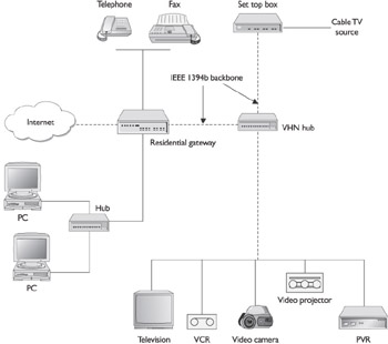
Figure 17-5: An example of a VHN that integrates both IEEE 1394b and IP networking.
Universal Plug and Play (UPnP)
The underlying standard for most home networking architectures, including HAVi and VHN, is UPnP, a Microsoft tool that provides discovery functions to dynamic network environments, like those we’ve been discussing. UPnP uses a series of IP-compatible protocols to provide services that discover and configure new devices added or removed from a network.
Internet Media
More and more the Internet is becoming a source of digital media. In the recent past, we’ve seen the tussles of Napster and KaZaA with the recording industry and copyright issues. However, with the emergence of pay-per-download sites, such as Apple’s iTunes.com (www.apple.com/music/store) and BuyMusic.com (www.buymusic.com), and free-to-listen sites, such as Lycos Rhapsody (http://music.lycos.com/rhapsody) and Yahoo! Launch (launch.yahoo.com), you can download and enjoy music and video without risking heavy fines, being hauled into court, or going to jail.
On some “jukebox” sites, you can create a play list and listen to your favorite music via a streaming audio feed in much the same way you would listen to the radio, which is something else you can do online. The Internet is a very broad range receiver and allows you to listen to radio stations around the globe or those created especially for the Internet.
The number of video sources on the Internet is also growing. Sites such as MovieFlix.com (www.movieflix.com) and InternetMovies.com (www.internetmovies.com) allow you to open a streaming download of a movie and watch it on your desktop. Of course, the problem with watching a streaming download is that you can’t save it to disk. If you want to watch the movie again or stop it and finish watching it later, you’d have to pay and download the movie again.
This problem is being solved by web sites such as MovieLink.com (www.movielink.com) that will sell or rent a (24-hour) license for a movie and allow you to download and store it on your computer for later viewing. It can’t be that long before you’ll be able to direct the stream to your PVR.
Streaming Media Types
Way back in 1995, before streaming technologies had come along, to play back an A/V file, the entire file had to be downloaded and stored before the playback could begin. At the data transfer speeds available at that time, a ten-minute video clip could take anywhere from two minutes to two hours to download.
With the advent of streaming media technologies, the content in an AV file can begin its playback as it is being downloaded and before the entire file is downloaded. Of course, heavy traffic on the Internet or an interruption in the connection can cause the sound or picture to break up or hesitate, but that’s the price we pay for convenience.
There are actually two types of media streaming:
- True streamingThis is the type of streaming described above. Playback of the AV content begins after only a portion of the file is received and it is continuous while the remainder of the file is received. True streaming is commonly used for longer AV files.
- Progressive streamingBefore the playback of a file begins, a significant portion of its contents must be received. This streaming method is common for short media pieces of 15 seconds or less and allows users to save the file to their hard drives for later viewing.
If you were to download a movie file from a pay-per-view site on the Internet, most likely the movie would be streamed to you using true streaming. However, if you were renting the movie for a period of time, the file would be streamed to you progressively so you could save it to disk.
Streaming media can include virtually any AV content that can be recorded, including text, recorded video or audio, still images, and live radio or television broadcasts. All of these media types can be consolidated into a single streaming file, provided the originator and the receiver each have the sufficient bandwidth to support it.
There are three major proprietary and distinct streaming technologies in use on the Internet: RealNetworks (RealMedia), Apple QuickTime, and Windows Media. At one time, to play back a file created for a particular media player, you needed to use that specific player. This is not the case anymore; with the exception of QuickTime, the players now play back each other’s technologies.
Streaming Media File Formats
The most common streaming media file formats in use on the Internet are those that match up with the three most common streaming media players:
- RealMediaThe two primary file types used are RAM and RPM
- RARealAudio clip
- RAM RealMedia file
- RM RealVideo and RealFlash clips
- RPM RealMedia plug-in file
- QuickTime
- MOVQuickTime movie file
- QT, QTL, and QTMQuickTime AV files
- QTV and QTVRQuickTime virtual reality movie files
- Windows Media
- ASFWindows Media Advanced Streaming Format file
- AVIWindows Media AV Interleaved file
- WMAWindows Media audio file
- WMVWindows Media AV file
- WMXWindows Media play list file
There are a few other open standard media file formats in use, with likely more to come, but for now the more popular ones are:
- MPEG-2This media type is used commonly in digital TV, interactive graphics, and interactive multimedia. Don’t confuse MP3 files with MPEG-3. MP3 files are actually MPEG-2 Layer 3 files.
- MPEG-7This is an emerging standard that will allow users to search for audio and video files by their content.
- Multipurpose Internet Mail Extension (MIME)There are several MIME file types, but only two AV file types: audio and video.
Video Receivers, Televisions, and Monitors
If the customer wishes to configure and install a home theatre or just merely connect her television set to the audio/video/computer-integrated network, there’s more to it than just plugging the TV into the network.
Along with any decisions to be made about the wiring, speaker placement, seating arrangements, and the like, there are a number of video system issues that must be considered, including screen formats, amplifiers and receivers, sound formats, DVD or CD capabilities, and the display device itself. Once you have a clear understanding of the customer’s vision, you can work through these issues to design and implement the customer’s dream system.
Video Screen Formats
One of the primary considerations when choosing a video display device is aspect ratio. Occasionally when you watch a movie on television, or a rented DVD or video, the image is centered vertically on the screen and the top and bottom portions of the screen are black boxes. The black areas are called letterboxes and are the result of a video signal that is set for a different aspect ratio than your television or monitor supports. In this case, the video is playing back in widescreen and not full screen.
Aspect Ratio
The aspect ratio of any display device, including televisions and monitors, states the number of picture elements (pixels) used horizontally and vertically to form the displayed image. For example, most display devices are set for an aspect ratio of 4:3, or four to three. This means that for every four horizontal pixels used in the display, three vertical pixels are used. Another way to think about this is that the image is displayed about 1.33 times wider than it is tall. Widescreen video is set for a 16:9 aspect ratio, which is why it doesn’t always exactly fit on a home television set. The 4:3 aspect ratio has the early standard for the movie industry.
When television became popular in the 1950s, it too adopted the 4:3 aspect ration, so it could show movies in their standard form. To compete with television, the movie industry began creating different screen formats, especially those that provided a wider or larger image display, such as CinemaScope and Panavision. Today the recognized standards of the movie industry are 1.85:1, which is called Academy Flat, and 2.35:1, which is called Anamorphic Scope. These standards are often translated into a standard aspect ratio of 16:9, or 16 units of width for each 9 units of height.
Three methods are used to fit the motion picture’s 16:9 aspect ratio onto the television’s 4:3:
- LetterboxWhen a 16:9 picture is fitted onto a 4:3 television frame, the result is black bars at the top and bottom of the displayed picture. This reduces the displayed image to what can be likened to a mail slot or a letterbox. This is a common effect from DVDs.
- Pan and scanThis method produces a full-screen display at the cost of picture quality. The image is created by panning and scanning left to right in order to fit the entire picture on the display. This method is common with VHS tapes and movies shown on broadcast television.
- Movie compressionThis method forces the 16:9 image into the 4:3 display and produces images that are taller and thinner in appearance than intended.
Of course, the solution to the incompatibility between 16:9 and 4:3 is to display the image on a display device that can handle the widescreen aspect ratio of the movie.
Resolution
A display characteristic closely related to the aspect ratio is resolution that defines the number of pixels used to produce the displayed image. As more pixels are used to display an image, the image quality improves.
The resolution of the displayed image on a television or monitor can be the result of any one, two, or all of the following factors:
- Transmission qualityThe extent to which the resolution of the original picture when it is broadcasted or stored (like on a DVD) is retained has a direct bearing on the resolution of the displayed image.
- Recording qualityThe resolution used to capture live or art-based images can impact the resolution that can be produced by the display device during playback.
- Displayed resolutionThe resolution that a display device is capable of producing is the final link in the picture quality of a displayed image.
Nearly all display devices produce an image by electrifying clusters of RGB dots. Just like the images in a black and white newspaper are made up of dots of black printed on a white background, where the number and separation of the dots causes the human eye and brain to form a picture using shades of black and gray, a television uses illuminated RGB dots (see Figure 17-6) that the human eye and brain can make into images.

Figure 17-6: A color display picture element (pixel) is made up of red, green, and blue dots.
Most conventional television sets and computer monitors use a picture tube that is a Cathode Ray Tube (CRT). A CRT produces an image by illuminating color dots with an electron beam, as illustrated in Figure 17-7. The intensity used to illuminate a pixel and its proximity to other pixels causes the human eye to assign a color or shade to that area of the screen. It is the number of pixels horizontally and vertically used to create the displayed image that defines a display’s resolution.
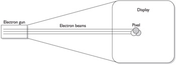
Figure 17-7: An electron beam is used to illuminate picture elements (pixels) on a CRT’s display.
| Note |
Although the CRT is used to explain the concepts of displaying an image, these characteristics also apply to other display types, including liquid crystal display (LCD) and plasma. Display types are discussed later in the section “Video Display Devices.” |
The CRT and virtually all other display types must refresh the display constantly to keep each pixel illuminated (the brightness of an illuminated pixel begins to fade almost immediately) and to accommodate changes in the image, like the motion in a motion picture. To refresh the screen, the electron gun sweeps (scans) the screen in a left to right, top to bottom pattern, sometimes in multiple zones of the screen simultaneously. Figure 17-8 illustrates a common scan pattern for a CRT display device.
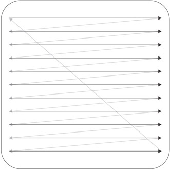
Figure 17-8: The scan pattern used by a conventional CRT display
The common resolutions for television, recorded, or broadcast images use 525 horizontal scan lines (top to bottom) on the display screen. The resolution of the display is stated as the number of pixels available on each horizontal scan line. The most common advertised horizontal resolutions for television sets are 240, 425, 500, with some even higher. The number of scan lines on the display establishes the vertical resolution for the display, typically 525 scan lines. So, for an average television set, the resolution could be 500 by 525, or 500 horizontal pixels and 525 vertical pixel rows (scan lines).
Of course, the size of the display and the size of each pixel has a direct bearing on the number of pixels that will fit on each horizontal line and the number of scan lines that can be fit onto the screen. The higher number of pixels, the better the display can deal with diagonal or circular lines.
It is important to note that a display doesn’t use all of its scan lines in the NTSC standard—the standard used for broadcast television—to produce an image. There picture uses only 480 of the 525 scan lines, and each line has only 440 pixels visible, to create a 480 by 440 picture grid.
Dot Pitch
Another factor of resolution is the dot pitch, or the proximity of the pixels (see Figure 17-9), on the display. This factor applies to virtually all displays, including rear projection units as well.
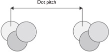
Figure 17-9: Dot pitch measures the space between picture elements.
Video Display Devices
Video display devices, or terminal devices that can reproduce video images, and typically audio sound, from either an amplified digital or analog signal, are available in a variety of types and sizes, with a variety of capabilities.
The most common video display device types are:
- CRT
- Flat panel
- Projection
Note CRT displays, actually standard television sets, are discussed in the preceding section.
Flat Panel Displays
It wasn’t that long ago that hanging a television screen on a wall like a piece of art was considered science fiction. However, with the development of flat panel technology, a variety of displays are available that can be hung on the wall or placed on a narrow table. It is no longer necessary to assign floor space solely to a television. Flat panel screens, like the one shown in Figure 17-10 can be set on furniture, hung on the wall, ceiling, or placed just about anywhere.
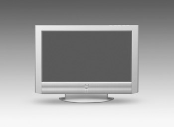
Figure 17-10: A flat panel television display
Photo courtesy of Sony Electronics, Inc.
Flat panel display devices are currently available using two primary display technologies: advanced liquid crystal display (LCD) and plasma.
LCD DisplaysLCD screens use positive and negative voltage to rotate the polarization of the crystals to either pass or block light through the crystal. The crystals form the pixels used to produce the displayed image. LCD televisions are backlighted and the crystals reflect and manipulate the light. LCD displays are available in sizes that range from 6 inches, measured diagonally, to 45 inches (and soon larger, we’re sure).
Plasma DisplaysPlasma displays have been in use for a number of years in point-of-sale monochrome displays and other similar uses. However, using a plasma display as a television monitor, as in Plasmavision, is a relatively new use of this technology.
The technology of a color plasma display is very similar to that used in a conventional CRT (discussed earlier in the section “Video Display Devices”). The display consists of an array of RGB cells (pixels). An electrical current reacts with the cells that contain gas in its plasma state that is conductive to produce light in an RGB color. Unlike LCDs, plasma displays produce their own light source and are not backlighted. Plasma screens are available in sizes that run from 30 inches to more than 60 inches.
The advantages of a plasma television display are:
- Higher resolutionCompared to standard, and even some DTV sets, a plasma display uses 1024 by 1024 pixels to display its images.
- Wide aspect ratioPlasma displays have a 16:9 aspect ratio.
- Flat screenA CRT screen is curved and can distort an image along the side edges and in the corners. This is eliminated on a flat screen and the picture can also be viewed from wide angles as well.
Plasma Displays Versus LCDsLCDs seem to have an edge in terms of quality and reliability over plasma displays. The most commonly cited advantages of LCD over plasma are:
- LCDs produce an image that is crisper and brighter than a plasma display.
- LCDs don’t have a burn-in effect, like a plasma display does, where the phosphors used to produce an image etch the glass covering of the display and produce ghost-like images.
- Using today’s technology, LCDs have a longer life of approximately 50,000 hours versus approximately 30,000 hours for a plasma display.
- LCD televisions weigh 10 to 15 percent less than a plasma television of the same size.
- LCD displays are more readable in daylight, though plasma displays have a brighter display in a darkened room.
Video Projection Systems
One of the options available for a home theatre system, meaning beyond a standard television set or an LCD or plasma television, is a video projection system (see Figure 17-11). These devices project the images transmitted to them on a screen or virtually any flat surface.
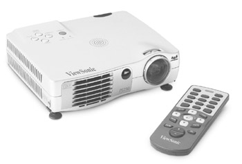
Figure 17-11: A video projector is used to project a television image on a screen.
Photo courtesy of ViewSonic Corp.
The most common types of video projectors use one of two technologies:
- Digital light processing (DLP)A DLP projector directs light through a rotating RGB filter onto a digital micro-mirror device (DMD) chip that reflects the colored light out of the projector’s lens and onto a screen. The DMD chip is covered with more than 900,000 micro-mirrors, each producing one pixel of the displayed image.
- LCD technologyAn LCD projector uses three LCD glass panels, one each for red, green, and blue, to project the image transmitted to the projector. The light that is passing through the color glass panels is controlled using LCD technology and the opening and closing of the liquid crystals.
DLP and LCD projectors are typically front or forward projectors and both are commonly used as ceiling-mounted projection systems. The major difference between LCD and DLP projectors is color adjustment. Because an LCD project uses separate controls for RGB, its brightness, color, and contrast can be adjusted at the color channel level. This adjustment process can take quite a bit of time: four hours or so. An LCD projector typically produces a brighter display. On the other hand, the color settings on a DLP projector are essentially fixed in place and require minimal or no adjustment.
Personal Video Recorders
For most downloaded AV files, once you have them stored on a computer hard drive, it is a simple matter of opening them to play them again. However, what about storing live television or radio for later playback? Well, there are two ways to go: use a PVR or convert a personal computer (PC) into a digital video recording device.
In order to pass an AV file intact between one device and another, the AV content has to have been recorded in a digital format. This can take place on a computer, digital video camera, or a digital video recorder (DVR).
Adding a PVR device to a home network allows a homeowner to expand the capabilities of a traditional video system. Products are now available that incorporate live Internet streaming, video archiving, and format translation directly into the network (see Figure 17-12). In other words, having an integrated PVR function on the network is like having an AV studio with an IP address.
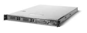
Figure 17-12: An IP-addressable DVR that can be added into a home network
Photo courtesy of Digital Rapids Corp.
Other PVR devices such as ReplayTV and TiVo can record up to 80 hours of television in digital format. PVRs can be stand-alone devices, like the ReplayTV shown in Figure 17-13, or they can be built into set-top devices, such as a digital broadcast satellite (DBS) receiver.
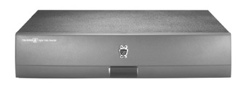
Figure 17-13: A personal video recorder (PVR)
Photo courtesy of TiVo, Inc.
Some other features of PVRs are:
- Share recorded programsTwo PVRs can share recorded content room to room as a streaming file, as a file transfer, or as a file transfer over the Internet.
- Digital audio outputConnects the PVR sound output into a sound system.
- Instant replayJumps back in seven-second intervals to replay a missed segment.
PC Based PVR
A home computer can also be used as a PVR by installing a PVR expansion card into the computer. Products like the one shown in Figure 17-14, enable a user to watch TV on a PC and to record from a cable or antenna television feed or stereo FM radio, as well as other digital video sources.
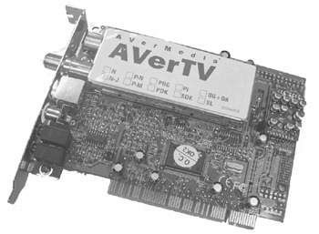
Figure 17-14: A TV PVR expansion card converts a desktop PC into a personal video recorder.
Photo courtesy of AverMedia Technologies, Inc.
Media Servers
In the context of home automation, a media server refers to any network computer or network device that uses UPnP to recognize and connect to any consumer electronic (CE) device and supports any AV content produced by the CE device. In the UPnP world, devices like VCRs, CD players, DVD players, audiotape players, digital cameras, digital camcorders, radios, PVRs, televisions, set top boxes, and, of course, a computer, can all be a media server.
A media server acts as a go-between to mitigate the various file formats used by the different AV devices and provides a compatible format to each device wishing to access media files. The functions performed by a media server include:
- Identifying the media content provided to clients on the home network
- Processing requests for media content from networked devices and negotiating a common transfer protocol and file format
- Controlling the transfer of media content to target devices
The term media server is commonly used in connection with Voice over IP (VoIP) functions, and in instances where a customer wishes to install VoIP functions on a home network, a media server function must be present on the network. VoIP media servers are normally created with the installation of the VoIP control software.
Review
Video signals are broadcast in either an analog or a digital format. Analog signals are RF signals that are broadcasted through the air and received by a home TV antenna or transmitted over a cable system. Digital video signals are transmitted over a cable system.
Broadband coaxial cable is capable of transmitting 130 analog channels; baseband video cable is capable of carrying only a single video or an audio transmission. The video device used to convert baseband to broadband signals is a modulator.
In situations where a single RF video source is to be transmitted to more than one end-device, a splitter is used. Another RF signal device used in a distributed video system is a combiner, which combines two (or more) incoming RF signals into a single broadband signal.
Splitters, combiners, and even connectors can impact the video signal’s strength. An amplifier is used to compensate for the signal loss on the line. An isolation amplifier can be installed on the incoming line to provide sufficiently high enough gain. A main system amplifier with a variable output level may also be used. An amplifier increases the gain of the incoming signal.
A receiver is an AV device that receives broadcasted signals and converts them for viewing or listening. The most common video receiver is a television set.
There are a variety of video signal formats in use in video distribution systems as well as on computers. The primary video signal formats are: RGB, component, S-Video, and composite. The three primary coding schemes or broadcast standards are: NTSC, PAL, and SECAM. The most common video signal format is S-Video, which is supported by virtually all AV amplifiers.
HDTV is one of the digital television standards defined by the ATSC. Digital TV transmits using binary data (using positive and negative electrical impulses to represent ones and zeroes, just like a computer uses) to encode its images and audio. HDTV can be delivered to a home using one of the following four methods: broadcast digital satellite, over the air broadcasting, recorded media, and terrestrial cable.
Several new AV standards are emerging, including HAVi, IEEE 1394, Jini, VHN, and UPnP. In addition, Internet-ready devices can support two types of media streaming: true streaming and progressive streaming. The primary streaming media formats are RealMedia, QuickTime, and Windows Media. Other open standard file formats also used for Internet media are MPEG-2, MPEG-7, and MIME.
The primary considerations when choosing a video display device are aspect ratio, resolution, and dot pitch. Different methods are used to display incompatible aspect ratios: letterbox, pan and scan, and movie compression. Resolution is the number of pixels used to produce a displayed image. It is the result of three factors: transmission quality, recording quality, and display resolution. Dot pitch is the proximity of the pixels on a display. The most common video display device types are CRT, flat panel, and projection.
Storing live television or radio for later playback can be accomplished using a PVR. A media server refers to any networked computer that connects to any consumer electronic device.
Questions
- Which of the following standards makes a network appear to be a single computer?
- VHN
- HAVi
- Jini
- UPnP
- What is the backbone architecture used with the VHN standard?
- IEEE 1284
- IEEE 802.3
- IEEE 1394b
- IEEE 802.15
- What is the underlying discovery function in HAVi and VHN?
- UPnP
- IEEE 1394
- True streaming
- IP
- What type of file is an AV file where playback can begin prior to the entire file being received?
- Digital
- Streaming
- Analog
- Progressive
- What differentiates a progressive streaming file from a true streaming file?
- A significant portion of the file must be received before playback begins.
- Only a small portion of the file must be received before playback begins.
- All of the file must be received before playback can begin.
- There is no substantial difference between a progressive and a true streaming file.
- Which two of the following are technologies used with flat panel displays?
- CRT
- DLT
- Plasma
- LCD
- Which of the following aspect ratios produces the widest displayed image?
- 4:3
- 1.33:1
- 16:9
- The aspect ratio doesn’t affect the width of the display.
- What video display characteristic most affects the clarity of the displayed image?
- Aspect ratio
- RGB
- Resolution
- Refresh rate
- What is the common name for a device that records from a digital television feed preset by a user?
- Digital object recorder
- Video cassette recorder
- Personal video recorder
- Personal object recorder
- What is the device or service that coordinates and supports the AV content produced by UPnP CE devices on a home network?
- VoIP server
- Media server
- Media client
- UPnP server
Answers
- C. This Sun Microsystems protocol creates seamlessness for the network for all devices. VHN and HAVi are home AV network standards and UPnP is a device discovery and configuration protocol commonly used with CE.
- C. Remember that the b version of IEEE 1394 is a faster, more robust version. The other choices are printer and Ethernet networking standards.
- A. UPnP is commonly used in most home AV standards.
- B. Of course it may be digital, but that has nothing to do with its playback format. It could be progressive, but it must first be streaming. Analog files aren’t streamed.
- A. As opposed to a streaming video file, more of a progressive streaming file must be buffered (received) before its playback can begin.
- C, D. CRT is the picture tube in a conventional television and DLP is the technology used in one type of a projection television.
- C. The standard aspect ratio for widescreen displays is 16.9. 4:3 and 1.33:1 are equivalent aspect ratios. Choice D is absolutely false.
- C. The higher the resolution capability on a display, the better the picture quality is likely to be, subject to the resolution of the original image. None of the other choices have much to do with the clarity of the displayed image.
- C. PVRs are also called digital video recorders (DVRs).
- B. A media server is also a central component of a VoIP network.
Part I - Home Technology Installation Basics
- Wire and Cable Basics
- Connector Types and Uses
- Wiring Installation Practices
- Codes, Standards, and Safety Practices
Part II - Structured Wiring
- Infrastructure Wiring Basics
- Planning a Structured Wiring Installation
- Rough-In Installation
- Trim-Out Installation
- Troubleshooting Structured Wiring
Part III - Home Computer Networks
- Computer Network Basics
- Computer Network Hardware
- Computer Network Software
- Designing and Installing a Computer Network
- Troubleshooting a Home Network
Part IV - Audio/Video Systems
- Distributed Audio System Basics
- Designing and Installing Distributed Audio Systems
- Distributed Video Basics
- Designing and Installing Distributed Video Systems
- Troubleshooting Audio Systems
- Troubleshooting Video Systems
Part V. Home Lighting Management Systems
- Home Lighting Basics
- Home Lighting Devices
- Designing a Home Lighting Control System
- Installing a Home Lighting Control System
- Troubleshooting and Maintaining Lighting Control Systems
Part VI - Telecommunications
- Home Communication System Basics
- Designing and Installing a Home Telephone System
- Troubleshooting a Home Communication System
Part VII - HVAC and Water Management
Part VIII - Security System Basics
- Security System Basics
- Designing a Home Security System
- Installing a Home Security System
- Troubleshooting and Maintaining a Home Security System
- Home Security Surveillance Systems
- Home Access Control Systems
Part IX - Home Technology Integration
- Defining Users Needs and Desires
- User Interfaces
- Home Automation Controllers
- Programming
- Integrating the Connected Home
- Other Home Technology Integration Devices
Part X - Appendices
EAN: N/A
Pages: 300
