Home Communication System Basics
Home CommunicationSystem Basics
In this chapter, you will learn about
- Home telecommunication system characteristics
- Telephone operations and fundamentals
- Intercom operations and fundamentals
- Telephone and network integration
- Telecommunication system service options
For those of us old enough to remember rotary dial telephones and dialing without an area code (to really date ourselves), the telephone and telephone service has drastically changed over the past couple of decades. In this chapter, we discuss telecommunications systems for the home, including telephone and intercom systems, their functions, operations, and characteristics. We also discuss the possibilities of integrating a home telecommunications system into control and data networks.
Telecommunications Basics
In most cases, a home telephone and telecommunications system is limited to RJ-11 outlet jacks (Figure 26-1) in one or two rooms of a home that is more than seven to ten years in age or in just about every room of a newer home. The telephone outlet jack can be used for local and long distance calling, to support a fax machine, as a part of a cable or direct satellite TV system, or to support a dial-up modem connection for either a single computer or a computer network. Actually, when you think about it, that little telephone jack really has quite a bit of capability, which is generally underutilized in most homes.
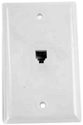
Figure 26-1: An RJ-11 jack faceplate
Photo courtesy of Belkin Corporation.
The Telephone System
Most people take the telephone system for granted and get very used to the idea that, for the most part, it always works. Before you can begin designing a home telecommunications system, you should have some understanding of how this system works and its various components.
The telephone network consists of two network layers: the Plain Old Telephone System (POTS) and the Public Switched Telephone Network (PSTN). POTS service consists of the wiring and cabling that connects a house to the local telephone company switching system at the telephone company’s network interface device (NID) on the side of the house. PSTN includes the switching system and all of the equipment and transmission lines used to carry the voice signals to the house by the phone company.
The Connection to the Central Office
The line that runs back to the telephone company or the telephone service provider (aka the Telco) terminates at a house in what is called the demarc. The demarc (short for demarcation point) is a terminating device that connects the wires in the Telco bundle to the home. In many respects, the demarc is very much like a network’s patch panel (see Chapters 11 and 13) in that it interconnects the telephone wiring in the home to the Telco’s cabling and switching systems.
Demarcation PointThe demarc device is typically located on an outside wall of a home or in an easily accessed location, such as inside a garage or basement. The official name for the telephone demarc is a Network Interface Device (NID), and it is commonly a gray plastic or metal box with a snap-tight cover (see Figure 26-2).
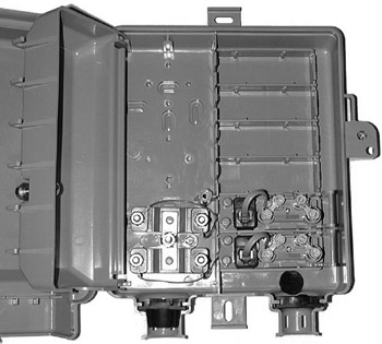
Figure 26-2: A Network Interface Device (NID) showing both the Telco-only side (left panel) and the owner-access side (right panel) connections
As shown in Figure 26-2, an NID has two sections, the panel of connections on the right side of the box are accessible by the homeowner or their contractors for testing and connection purposes, and the panel of connections on the left has an inside cover and is accessible only by Telco personnel. The owner-accessible panel, Figure 26-3 gives a zoomed-in view, has four to six screw connectors that connect the Telco’s incoming lines (the connections made in the Telco-accessible panel) to the short piece of telephone cables that are plugged into the RJ-11 jacks. When the RJ-11 plug is removed from the jack, the line (and service) from the Telco is disconnected. However, if a phone is plugged into this jack and works during a service test, any problem with the phone system in the house is being caused by the inside wiring, not by the Telco service.
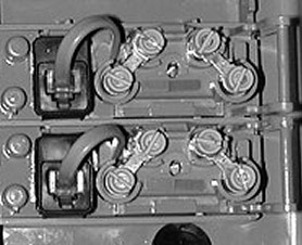
Figure 26-3: A close-up of the owner-accessible panel in an NID
The demarc is where the Telco’s lines and system meet the telephone lines of the homeowner. The Telco owns the lines up to the demarc (and most times the demarc itself), but no further. Beyond the demarc, everything belongs and is the responsibility of the homeowner. However, especially on new homes, some homeowners are choosing to install their own NIDs, which aren’t expensive. Installing and owning the demarc allows for more flexibility for expanding the telephone system inside the home, better quality connections at the demarc, the ability to complete the inside wiring (to the demarc) even before the telephone service is installed, and perhaps the best reason, the homeowner can put the demarc wherever they wish. However, the Telco’s responsibility ends at the terminator on their cable, which may be a good reason to let them install their NID.
The Central OfficeThe wiring that connects a house to the telephone network actually connects the NID to the wiring and intermediate devices that lead back to the nearest switching center for the Telco, called a central office (CO). Figure 26-4 illustrates the basics of the connections that link a house to the CO.
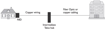
Figure 26-4: Telco lines connect a house to the Central Office for telephone service.
The Telco’s CO is a switching station that routes calls (including signals on DSL and ISDN services) to the location of the number being called. A CO handles all of the telephone traffic in a particular area. In smaller towns, the CO handles all calls and in larger areas, the CO handles a certain area of a city, county, or a specific area code.
Cabling and Entrance BridgesIf we look at the cabling used to provide a telephone service connection to a residence and start at the CO, in older situations, copper cabling with tens or even hundreds of wire pairs and, in newer lines, fiber optic cabling is used to distribute “dial-tone” (analog telephone services) to every home. In areas where the telephone cabling is installed underground, a device called an entrance bridge is located in the yards of each or every two, three, or more houses. This device is about 2 to 3 feet tall and about 8 inches square (see Figure 26-5) and is where 50 pairs of wiring comes up from underground to be interconnected into houses. On occasion, larger boxes that are about 4 or 5 feet tall and 2 feet wide are also located in neighborhoods that serve as intermediary bridges that distribute wiring to the entrance bridges.
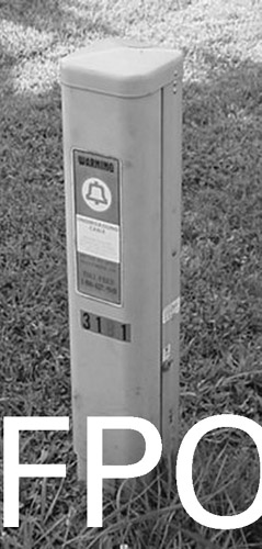
Figure 26-5: An entrance bridge is used to distribute telephone system wiring to individual houses.
Analog LinesAnalog telephone systems operate using voice and sound signals. Analog phone equipment is designed to interpret audible signals (of the number dialed) and route each call to its destination to build a temporary virtual circuit where the caller and the called can speak over their own private circuit. This circuit is torn down after the call is disconnected. Analog telephone lines support modem connections made by computers, as well as most of the voice transmissions over the Telco system.
Digital LinesDigital telephone circuits convert sound waves into digital (binary) signals for transmission to the other end of the connection where another telephone, modem, or even a television, converts the digital signals back to audible tones. The primary difference to the telephone user is clarity, because the digital system is able to remove any distortion in the signal. In addition, more features can be carried over the digital line than over an analog line.
By installing the proper switching and bridging equipment, existing telephone wiring can also be used to transmit digital data, such as with Digital Subscriber Lines (DSL), Integrated Systems Digital Network (ISDN), and frame relay services. Digital services use the existing copper and fiber optic cabling to transmit digital (binary) data rather than analog (audible) signals.
DSL is able to transmit data only over copper wiring and so it is available only to those houses that have only copper lines connecting them to the CO. Even if only copper wiring connects the home to the CO, DSL is a distance-limited service and may not be available to every home. The wire distance used to determine DSL service availability is the length of the wire itself. Table 26-1 lists the various flavors of DSL and the standard wire distance limitations for each.
|
144 Kbps ISDN over DSL (IDSL) |
37,000 feet |
|
256 Kbps Symmetrical DSL (SDSL) |
17,000 feet |
|
384 Kbps SDSL |
17,000 feet |
|
768 Kbps SDSL |
12,000 feet |
|
1.1 Mbps SDSL |
10,000 feet |
|
1.5 Mbps / 384 Kbps Symmetrical DSL (SDSL) |
12,000 feet |
ISDN and other digital transmission services can operate over both copper and fiber optic, so they are generally available to most homes, without wire distance limitations. However, ISDN requires that the residential terminating equipment match the type of ISDN switching used at the CO. The most common types of ISDN switching are AT&T 5ESS, Northern Telecom (NT) DMS-100, and National (ANSI) ISDN-1.
Dialing Systems
To place either a local call or a long-distance call requires a number of elements to be available:
- A telephone key set
- A dial-tone sound
- Telephone bandwidth
- Telephone number
Telephone Key SetsA telephone, or what is also commonly called a key set, has four primary parts:
- Hook switchThis is the part of the phone that opens and closes the circuit loop that tells the phone’s circuitry whether the phone is on hook (circuit open) or off hook (circuit closed). When the phone’s handset is lifted (or the speaker phone button is depressed), the circuitry of the phone detects that the loop is closed and plays the dial tone sound or passes sound through it.
- Keypad or rotary dialOn older phones, a rotary dial was used to emit pulses, with 0 to 9 pulses representing the numbers 0 to 9. Newer phones are almost all touchtone that emit a recorded sound at a certain frequency for each number pressed on the keypad. For example, as you dial the numbers in a phone number, the phone emits a stream of combined frequency tones, the combination represents each number on the keypad.
- MicrophoneA microphone is located in what is most commonly called the mouthpiece of a telephone’s handset. The microphone converts the sound it picks up into sound samples that are transmitted to the telephone system.
- SpeakerThe speaker in the handset of a telephone key set is a small 8-ohm speaker that plays back the audible signals transmitted to or played by the phone circuitry.
Dial ToneThe dial tone, as well as the tones representing the numbers dialed and several other common dialing sounds, such as busy, off-hook, and others, are recorded sounds embedded on a chip on the telephone’s circuitry.
All of the tones produced by a telephone are a combination of two frequencies. For example, combining a 350-hertz tone with a 440-hertz tone creates the dial tone and the busy signal is a combination of a 480-hertz tone and a 620-hertz tone that is cycled on and off.
System BandwidthThe public telephone system limits transmitted sounds to not less than 400 hertz and not more than around 3,000 hertz. Any sounds with frequencies below 400 hertz or above 3,000 hertz are discarded and this is why a person may sound completely different over the phone than in person, where you can receive the full range of their voice’s frequencies.
The telephone key set also limits the bandwidth requirement of voice communications by transmitting sound samples rather than the entire sound it receives. A concentrator circuit works with the telephone’s microphone to create 8,000 samples per second of the sound it hears and transmits the sound samples across the public telephone system for playback by the speaker at the other end’s handset.
Telephone Number DigitsLike the physical address of a networked computer (see Chapter 12) or the address of a home, a telephone number is a unique address for a destination circuit. Each part of a telephone number has meaning, from a country code used to dial an international call, the area code, the prefix, and the line number. For example, in the number 509-555-1212, the 509 is the area code, the 555 is the prefix, and the 1212 is the line number.
- Area codeArea codes in the United States are regulated and assigned by the Federal Communications Commission (FCC) to designate a specific geographic region that could be a part of a city or state. For example, 509 is the area code for Eastern Washington State. Each area code can address 7,920,000 prefix and line number combinations. In the United States, only around 215 area codes are in use out of the 680 usable areas.
- PrefixAt one time, the prefix represented a specific switch (at the CO) where a particular telephone is connected. However, since automated switches have been in use, phone numbers, included the prefix are now portable under a method called local number portability (LNP).
- Line numberThe CO switch identifies a specific line using the last four digits of a telephone number.
Caller IdentityMost newer telephone key sets are able to display the identity (the phone number and the name the phone number is registered to) of the calling party either on the phone itself or on a satellite caller ID box.
The technology used to provide caller ID isn’t new, in fact it is the same used by modems to set up a connection—frequency shift keying (FSK). This technology uses certain tone frequencies to represent binary digits, such as 1,200 hertz for a one and 2,200 hertz for a zero, and the telephone or caller ID box converts these to ASCII characters for display.
Wireless Telephones
To this point, we have been discussing telephones in general, so most of this information applies to the standard wire-connected telephone and key sets. However, it is common for today’s homes to include one or many cordless or wireless telephones, either in addition to or in replacement of standard telephones.
Cordless Telephones
A cordless telephone, like the one shown in Figure 26-6, allows a user to talk through the telephone’s handset without being tethered to the telephone’s base unit. As far as functionality goes, cordless phones have essentially the same features offered by a standard or corded telephone.
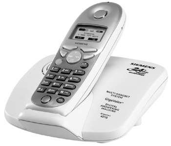
Figure 26-6: A cordless phone has two parts: a base and a handset, which is portable and not attached to the base with a cord.
Photo courtesy of Siemens Information and Communication Mobile, LLC.
RF FunctionsCordless telephones combine the functions of a standard telephone with those of radio frequency (RF) transmitter/receiver. The base of a common cordless phone is wired into the telephone system just like a standard telephone. However, the base communicates to the handset using RF communications and a frequency modulation (FM) signal. The handset receives the FM radio signal and converts it back to an audio signal and is sent to the handset’s speaker. The microphone on the handset performs an opposite action, translating the audio signals into FM radio signals for transmission to the base unit that converts the RF signals to voice signals for transmission through the telephone wiring.
The handset and base of a cordless telephone use a pair of different frequencies, one for incoming signals and one for outgoing signals. A frequency pair that is used this way is referred to as a duplex frequency. For example, the base unit may use 44 MHz to transmit and 49 MHz to receive, which is reversed on the handset where 49 MHZ is used to transmit and 44 MHz is used for the receiver.
Operational IssuesA cordless telephone does have a few operational issues that a standard telephone doesn’t have:
- Range limitationsThe operating frequency (RF band) of a cordless telephone has a direct impact on the operating range of the handset or the distance the handset can be from the base and continue to work properly. Table 26-2 lists the operating ranges for the more common frequencies used on cordless telephones.
Table 26-2: Conservative operating ranges for cordless telephone RF Bands Band
Operating Range (Upper Limit)
49 MHz
250 feet (75 meters)
900 MHz
1,500 feet (450 meters)
2.4 GHz
2,000 feet (600 meters)
5.8 GHz
2,000 feet (600 meters)
- Sound reproductionThe sound quality of a cordless phone’s handset is affected by a variety of things, including distance and interference created by obstructions, such as walls, or electrical appliances.
- Security issuesBecause a cordless phone transmits using RF signals on common radio frequency bands, the transmitted signals can be intercepted by other RF devices, including other cordless phones that operate on the same band, baby monitors, radio scanners, and the like.
The performance issues of a cordless phone are the result of the phone’s design and features, primarily the phone’s RF band, whether the phone is analog or digital, and the number of channels it has available.
Inexpensive cordless phones are commonly analog devices that are generally electrically noisier, susceptible to interference, and more easily intercepted by other RF devices. Digital cordless phones provide a better sound quality and, because they also use digital spread spectrum (DSS) signaling, they are generally more secure than an analog phone. DSS uses several frequencies to transmit signals between the base and the handset and this makes it very hard for another device to intercept an entire conversation.
RF frequency bands can be divided into several channels and the more channels available, the better chance the base unit is able to find a channel pair that is relatively free from interference. Typically, a 49MHz cordless telephone has from 10 to 25 channels available; a low-end 900 MHz phone has from 20 to 60 channels; and higher-end 900 MHz, 2.4 GHz, and 5.8 GHz phones have as many as 100 channels.
Residential Telephone Systems
If the homeowner desires only a single telephone line with multiple extensions without any added features, beyond those provided by the Telco, once the wiring and the phone jack outlets are installed during pre-wire, chances are that the house has everything it needs to fulfill this requirement.
However, if the homeowner wishes to have multiple phone lines accessible throughout the house, careful consideration must be given to exactly what features the homeowner is looking for and if a telephone system will meet their needs.
There are several advantages to a telephone system over the standard telephone service found in most homes. These advantages include:
- Call routingAn automatic call distribution (ACD) allows callers to select the direct line to a member of the household or leave a voice message for a specific user.
- Multiple phone line accessibilityAll phones have access to the phone lines connected to the phone system and allow for the automatic selection of the next available line—no current conversations can be interrupted by someone else in the home picking up the phone on the same line.
- Intercom capabilitiesAll phones, and even a door bell station, can be intercom stations and can be called from other phones in the house. Also, phones can be put on “private mode” so the room is not interrupted with the telephone ringing.
- ExpandabilityPhone systems are typically based on an expandable base unit to which additional features or telephones can be added or upgraded as the homeowners’ needs change.
- Fax/Modem connectionsA phone system can provide connections for a fax or modem without tying up a voice line.
- Voice and data integrationMany phone systems include the ability to integrate high-speed voice and data communications using computer telephony integration (CTI).
- Voice messagingPhone systems commonly have the ability to record outgoing announcements for each household member and record incoming voice messages in separate voice message boxes.
KSU-Based Systems
A KSU is a central device that provides the switching and control services for the entire network of key sets on a telephone system. In some cases, the KSU may also be referred to as a Public Branch Exchange (PBX) or a computerized PBX (C-PBX). Regardless, a KSU provides additional or advanced features to standard telephone sets, including such features as call forwarding, extension dialing, voice mail, music on hold, and more. The fact that a KSU must be configured in a star topology is considered a drawback to many, but structured wiring provides “star” topology, and a phone system can easily be installed on structured wiring. Most KSU-based systems may require proprietary or specially configured key sets that add to the overall cost of the system.
KSU systems provide many “business” functions as well, including auto-attendant that answers the phone with a recording and allows the caller to select an extension from a recorded menu, such as “For Ron, press 1; for Connie, press 2,” and so on.
KSU-based systems also offer a wide range of optional features as well, including:
- Automatic routing for fax calls to a fax machine
- Toll restriction that prevents certain users from placing certain outgoing toll or long-distance calls
- PC-accessible call and activity reporting
- Call-waiting
- Music on Hold from an external music source
- Three-party teleconferencing
- Do not disturb function that blocks incoming calls (internal and external) from ringing on a blocked extension
- Call pickup that allows calls on one extension to be picked up on another extension when put on hold
- The ability to connect a door phone or an intercom station to talk with visitors on any extension phone
- Interface to relay devices or AC outlets that allow home lights, appliances, and other devices to be turned on and off through the telephone
KSU-Less Systems
Another type of KSU system, at least in terms of functionality, is the KSU-less system. KSU-less systems are relatively low-cost options for residential phone systems with two to seven telephone lines. The primary attractiveness to a KSU-less telephone system, beyond its features that is, is that it can work with nearly any ordinary phone, including both rotary dial and touch-tone. However, to realize all of the features of the system, a central unit or specialized telephone stations may be required. KSU-less systems typically provide all, or at least the majority, of the features of a KSU-based system, but commonly at a much lower cost.
Digital Systems
Digital telephone systems are key systems like KSU-based systems and rely on a central processor for many of their functions. Digital key systems, also like a KSU system, allow the telephone system to share multiple CO lines across a number of key stations. Figure 26-7 shows the central unit and samples of the digital key stations for one residential and small business system.
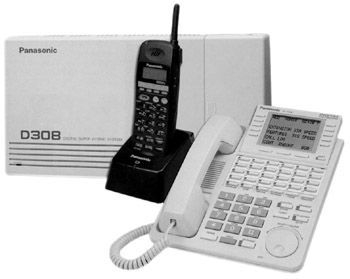
Figure 26-7: A digital telephone system with a digital PBX, key station, and cordless phone
Photo courtesy of Panasonic USA.
Because they have what amounts to a computer at their core, digital telephone systems are programmable, typically through a graphical user interface that can be accessed either by attaching a monitor to the central unit or connecting the central unit to a data network.
One of the downsides to a digital telephone system is that they require the use of special digital telephone key sets and any existing fax machines and modems must continue to use separate analog phone lines. On the other hand, however, the digital phones are feature-rich, including such features as:
- Automatic Call Distribution (ACD)Callers can use a hierarchy of voice prompts and menu choices to route themselves to the proper phone.
- Computer Telephony Integration (CTI)This feature supports the integration of some telephone functions with those of a computer network. A common CTI feature is the routing of voice mail into a user’s e-mail mailbox.
- Incoming and outgoing call logsDigital systems have the ability to store Calling Line Identification (CLID) information and prepare listings reporting call, time, and date information.
- IntercomMost digital systems provide intercom functions for station-to-station communications.
- Integrated Voice Response (IVR)This feature is less important for residential use, but can come in handy for home offices. IVR allows the voice response of information retrieved from a computer file or database. If you’ve ever called a credit card company for your balance, you were likely using IVR.
- Programmable key set buttonsEach key station on the system can be customized to the needs of the user.
- SpeakerphoneDigital phones provide high-quality audio, which facilitates hands-free conversations, teleconferencing, and background music playback, all with volume control.
- Speech recognitionThis feature allows callers to use voice commands to navigate through ACD menu choices.
IP Telephone Systems
Internet Protocol (IP) telephone systems operate over the cabling and computers of a data network. Residential IP telephone systems replace the existing residential gateway with one (see Figure 26-8) that provides both the RJ-45 network connections required by the data network and RJ-11 connections used to provide phone service to IP telephone key stations.
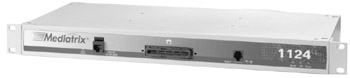
Figure 26-8: An IP telephone system residential gateway
Photo courtesy of Mediatrix Telecom, Inc.
The benefits of an IP telephone system are several, including cost-effective access through phones anywhere in the world that are connected to the Internet, and the fact that the system is relatively easy to install. The drawbacks of an IP telephone system primarily have to do with the performance. Sometimes there is a delay in the speaking, and clarity is not as consistently good as on a standard phone line. Also, signals can be lost more easily than on standard phone lines.
IP telephones use a technology called Voice over IP (VoIP) to transmit telephone calls over a data network in the same way that data messages are sent over the network. VoIP converts voice samples into network packets that are transmitted over both the local in-home network and the Internet.
VoIP uses coder/decoder (codec) circuitry to convert audio signals into compressed digital format for transmission and back to voice signals at the receiving station for playback. Two primary protocols are used by VoIP to transmit voice signals:
- H.323This is the international communications standard that specifies real-time, interactive teleconferencing, data sharing, and IP telephony.
- Session Initiation Protocol (SIP)This protocol, developed by the Internet Engineering Task Force (IETF) is a streamlined version of the H.323 protocols designed specifically to support IP telephone services. Because it is not a complete suite of protocols like H.323, SIP employs other protocols, such as the Media Gateway Control Protocol (MGCP), to establish gateway connections to the PSTN.
The primary ways VoIP can be used across the PSTN is in computer to telephone, telephone to computer, and telephone to telephone calling.
- Computer to telephoneThis calling method allows a user to call any telephone connected to the PSTN from a computer, using the computer’s speakers and microphone to communicate.
- Telephone to computerThis calling method allows a call to be placed across the network from a telephone to a computer. The computer user has the ability to answer the call by activating a software function or allowing the computer to answer the call, play an outgoing announcement, and record a voice message.
- Telephone to telephoneThis calling method is the one that employs the methodology and technology that can be used on a home network to place calls through the residential gateway to a PSTN-connected telephone.
Intercom Systems
There are two general categories of intercom systems that can be installed in a home: wired and wireless. There are two ways to implement an intercom system in a home: through the telephone system or through the installation of an independent, stand-alone wall-mounted intercom system.
Telephone-Based IntercomNewer key stations and analog telephones feature intercom and speaker-phone capabilities that allow the telephone to be used to call room-to-room, typically with the press of a single button, and talk with someone in another location in the house with a totally hands-free conversation.
Stand-alone Intercom SystemsWe refer to these systems as independent only to differentiate them from telephone-based intercom systems. This type of intercom system consists of master units, remote controls, speakers, and now even displays that are typically wall-mounted devices placed at the mouth-level of the average person.
There are a variety of stand-alone intercom systems available:
- Doorbell intercomThis type of intercom system includes a doorbell for visitors to ring the standard phones in the house with a unique ring-ring to identify it is the doorbell intercom and not an incoming phone call. When a phone is answered in the house, the connection becomes a two-way voice intercom that allows the homeowner to speak with the visitor. Some systems also include the ability to remotely open or unlock a door.
- Voice-only intercomThis is the type of intercom system that is implemented on a telephone system and on low-end intercom systems. Low-end voice intercom systems typically only support half-duplex (two-way communication, but only one way at a time) conversations where the user must push a button to speak or announce. Voice-only intercom systems implemented on KSU, KSU-less, or digital telephone systems generally support full duplex (two-way communications, two ways at the same time) conversations.
- Voice/radio intercomThese systems represent the mid-range in cost and capability in intercom systems. Many limit voice communications to half-duplex, but more full-duplex systems are now available. The master unit of a voice/radio intercom includes an AM/FM radio that can be played throughout the system. Some newer models also include playback units for audiocassettes or CDs.
- Video intercom systemsVideo intercom systems are primarily used to identify someone at a doorway or other secured areas. These systems incorporate a voice intercom and video capture and display and are available with a single built-in, wide-angle camera or have the ability to connect to multiple external cameras. The video image can be one-way, where only the master unit inside the house has a video screen, or two-way, where both the inside and outside devices have displays.
Review
The telephone network consists of two network layers: the Plain Old Telephone System (POTS) and the Public Switched Telephone Network (PSTN). POTS refers to the wiring and cabling connecting a house or building to the local CO. The PSTN includes CO and the equipment and transmission lines that carry voice signals to a destination.
The Telco’s POTS line, which terminates at a house at the demarcation point (demarc) or Network Interface Device (NID), is a terminating device that interconnects Telco wiring to a home’s telephone wiring. The demarc is commonly located on an outside wall of the house. The Telco owns the lines up to the demarc (and most times the demarc itself), but all internal telephone wiring is the responsibility of the homeowner. The POTS lines connect a house to the Telco’s central office (CO) or switching facility. The CO routes calls to the CO and switching associated with the number being called.
Analog telephone systems transmit voice and audio signals. Analog telephone lines also provide support for modem connections made by computers. Digital services use the existing copper and fiber optic cabling to transmit digital (binary) data rather than analog (voice) signals. Digital services include DSL and ISDN.
A telephone set has four primary parts: hook switch, keypad or rotary dial, microphone, and speaker. Combining two audible frequencies creates the tones produced by a telephone. For example, combining a 350-hertz tone with a 440-hertz tone creates the dial tone.
The telephone system transmits sounds between 400 hertz and 3,000 hertz. Sounds below or above this range are discarded and this is why people sound different on the phone than in person. Telephone key sets transmit sound by creating 8,000 sound samples per second.
Each part of a telephone number has meaning. A telephone number typically consists of an area code, a prefix, and a line number. Caller ID uses frequency shift keying (FSK) to transmit ASCII caller identification information.
A cordless telephone includes a stationary base unit and a portable (unwired) handset. Cordless telephones combine a standard telephone with a radio frequency (RF) transmitter/receiver. The cordless phone base communicates to the handset using RF communications and a frequency modulation (FM) signal.
There are three primary types of residential home telephone systems: KSU-based systems, KSU-less systems, and digital key systems. A KSU is a central device that provides the switching and control services for the entire telephone system. KSU-less systems are relatively low-cost options for residential phone systems with two to seven telephone lines and work with standard telephones. Digital key systems rely on a central processor for their functions and provide advanced features.
Common features for residential telephone systems are: Automatic Call Distribution (ACD), Computer Telephony Integration (CTI), intercom capability, programmable key set buttons, speaker-phone compatibility, and speech recognition.
Internet Protocol (IP) telephone systems operate over the cabling and computers of a data network. Residential IP telephone systems replace the existing residential gateway with one that provides both RJ-45 network connections and RJ-11 connections to IP telephone key stations.
IP telephones use a technology called Voice over IP (VoIP) to transmit telephone calls over a data network in the same way that data messages are sent over the network. VoIP converts voice samples into network packets that are transmitted over the local in-home network and the Internet. VoIP uses coder/decoder (codec) circuitry to convert audio signals into compressed digital format for transmission and back to voice signals at the receiving station for playback. VoIP provides support for computer to telephone, telephone to computer, and telephone to telephone calling.
Three general types of intercom system can be used in a home setting: doorbell intercoms, stand-alone voice intercom systems, and intercoms integrated into phone systems.
Questions
- What connecting jack and plug standard is used for telephone system wall outlets and key sets?
- RJ-232
- RJ-45
- RJ-32
- RJ-11
- What is the name applied to the cabling used to connect a house to its local CO?
- PTSN
- POTS
- PSTN
- ISDN
- What is the common name for the device used to terminate the CO line to a house?
- POTS
- PSTN
- Telco
- Demarc
- What Telco device is used to distribute CO line wiring to individual houses or buildings?
- Multiplexer
- Entrance bridge
- Line splitter
- NID
- Which type of telephone system transmits a telephone call as audible signals?
- Analog
- Digital
- KSU
- KSU-less
- What is a high-speed broadband service that transmits over existing POTS lines?
- POTS
- PSTN
- DSL
- H.323
- What are the frequency ranges transmitted by telephone systems?
- 0 to 10,000 hertz
- 400 to 3.000 hertz
- 1,000 to 8,000 hertz
- 2,000 to 10,000 hertz
- What is the technology used to transmit caller identification information?
- PSTN
- DSL
- H.323
- FSK
- What technology do cordless phones use to transmit between the handset and the base unit?
- IR
- RF
- IVR
- DSL
- What digital key system feature allows for the integration of voice and data features and functions?
- ACD
- CLID
- CTI
- IVR
Answers
- D. RJ-11. An RJ-45 jack is used to connect twisted-pair wiring; the other choices don’t exist.
- B. POTS. The Plain Old Telephone System describes the analog wiring and service used to connect a CO to the demarc of a house. PSTN is the Public Switch Telephone Network that includes the switching systems of a Telco; ISDN is the Integrated Services Digital Network, which is a digital data system; and PTSN is not a Telco abbreviation.
- D. Demarc. Demarc is short for demarcation point, which is also called a Network Interface Device (NID). POTS and PSTN are the different network layers of the telephone network and Telco is a short-form of telephone company.
- B. Entrance bridge. An entrance bridge is a 2- to 3-foot tall device where the underground cable is distributed to individual buildings.
- A. Analog. Analog systems transmit signals in their native form without converting them into digital format. KSU and KSU-less systems are types of facility-based telephone systems.
- C. DSL. Digital Subscriber Line (DSL) service uses existing POTS lines to carry digital broadband signals. H.323 is an IP telephony standard.
- B. 400 to 3,000 hertz. This is the reason why people sound different over the telephone than in person.
- D. FSK. Frequency shift keying uses different frequencies to transmit binary-encoded ASCII data to a telephone set.
- B. RF. Radio frequency technology is used to connect the handset to the base of a cordless phone. IR (infrared) is not used for this purpose; IVR is a key system feature; and DSL is a POTS broadband technology.
- C. CTI. Computer Telephony Integration provides the ability for voice mail messages to be saved as e-mail messages. ACD, CLID, and IVR are other key system features.
Part I - Home Technology Installation Basics
- Wire and Cable Basics
- Connector Types and Uses
- Wiring Installation Practices
- Codes, Standards, and Safety Practices
Part II - Structured Wiring
- Infrastructure Wiring Basics
- Planning a Structured Wiring Installation
- Rough-In Installation
- Trim-Out Installation
- Troubleshooting Structured Wiring
Part III - Home Computer Networks
- Computer Network Basics
- Computer Network Hardware
- Computer Network Software
- Designing and Installing a Computer Network
- Troubleshooting a Home Network
Part IV - Audio/Video Systems
- Distributed Audio System Basics
- Designing and Installing Distributed Audio Systems
- Distributed Video Basics
- Designing and Installing Distributed Video Systems
- Troubleshooting Audio Systems
- Troubleshooting Video Systems
Part V. Home Lighting Management Systems
- Home Lighting Basics
- Home Lighting Devices
- Designing a Home Lighting Control System
- Installing a Home Lighting Control System
- Troubleshooting and Maintaining Lighting Control Systems
Part VI - Telecommunications
- Home Communication System Basics
- Designing and Installing a Home Telephone System
- Troubleshooting a Home Communication System
Part VII - HVAC and Water Management
Part VIII - Security System Basics
- Security System Basics
- Designing a Home Security System
- Installing a Home Security System
- Troubleshooting and Maintaining a Home Security System
- Home Security Surveillance Systems
- Home Access Control Systems
Part IX - Home Technology Integration
- Defining Users Needs and Desires
- User Interfaces
- Home Automation Controllers
- Programming
- Integrating the Connected Home
- Other Home Technology Integration Devices
Part X - Appendices
EAN: N/A
Pages: 300
- The Effects of an Enterprise Resource Planning System (ERP) Implementation on Job Characteristics – A Study using the Hackman and Oldham Job Characteristics Model
- Context Management of ERP Processes in Virtual Communities
- Healthcare Information: From Administrative to Practice Databases
- Relevance and Micro-Relevance for the Professional as Determinants of IT-Diffusion and IT-Use in Healthcare
- Development of Interactive Web Sites to Enhance Police/Community Relations
