Internet Protocol Security (IPSec)
Overview
In the increasingly hostile modern-day world of private and public networking, security and protection of data are fundamental requirements. To provide the best protection, you must deploy defense in depth: Many layers of security are needed to repel the types of attacks you might encounter on the Internet, and more likely, from within your own network. One of the ways to provide this defense, beyond the typical measures tosecure the network perimeter and secure access to resources by instituting authentication and access control, is to secure the actual IP packets and their contents.
As described in previous chapters, IP, TCP, and User Datagram Protocol (UDP) headers contain a checksum, which is used to provide a bit-level integrity check for portions of the IP packet. However, the checksum is only detecting corrupted data. Because the checksum algorithm is well known, a malicious user can intercept an IP packet, view and modify its contents, recompute the checksums, and forward the packet to its destination. Due to the limited functionality of the checksum, the destination node is not aware and cannot detect that the packet was modified.
Historically, applications that required security provided it for themselves, leading to a variety of separate and incompatible security standards. IP Security (IPSec) is a suite of protocols and cryptographic algorithms that provide security at the Internet layer, regardless of the application sending or receiving data. With IPSec, a single security standard is used and applications do not need to be modified to use it.
IPSec Overview
IPSec is an architectural framework of Internet Engineering Task Force (IETF) standards that provides cryptographic security services for IP packets. IPSec is an end-to-end security technology: the only nodes aware of the presence of IPSec are the two IPSec peers that are communicating. Intermediate routers have no knowledge of the security relationship and forward the IP packets, as they would any other, between the communicating peers.
Properties of Secure Communications
IPSec provides the following properties for secure communications:
- Peer authenticationIPSec verifies the identity of the peer computer before any data is sent. IPSec peer authentication for the Microsoft Windows Server 2003 family can be based on preshared keys, public keys (such as X.509 certificates), or Kerberos and the Active Directory service.
- Data origin authenticationEach packet protected with IPSec contains a cryptographic checksum in the form of a keyed hash. The cryptographic checksum is also known as an Integrity Check Value (ICV) or hash-based message authentication code (HMAC). A hash is a one-way, mathematical summary of a block of data. A keyed hash includes the secret key in its calculation. The cryptographic checksum ensures that only a computer with knowledge of the shared secret key could have sent the packet. A malicious user masquerading as the sender cannot calculate a correct cryptographic checksum. If the cryptographic checksum fails, the receiving peer discards the packet.
- Data integrityBy including the cryptographic checksum, IPSec protects the data in an IP datagram from unauthorized modification during transit, ensuring that the information that is received is the same as the information that was sent. A malicious user who modifies the packet contents must also properly update the cryptographic checksum, which is virtually impossible without knowledge of the shared key.
- Data confidentialityBy using conventional secret key encryption techniques, the sent data can be encrypted, providing data confidentiality. Even if the packet is intercepted and viewed, the interceptor can view only the encrypted data. Without knowledge of the secret key used to encrypt the data, the original data remains hidden. Because the secret key is shared between the sender and receiver, data confidentiality ensures that the data can be decrypted and disclosed only by the intended receiver.
- AntireplayBy using a sequence number on each protected packet sent between IPSec peers, a data exchange between IPSec peers cannot be captured and then portions replayed to establish a security relationship or gain unauthorized access to information or resources.
- Key managementData origin authentication, data integrity, and data confidentiality depend on the shared knowledge of a secret key. If the key is compromised, the communication is no longer secure. To keep malicious users from determining the key through any method except brute force determination (trying all possible key combinations until the key is discovered), IPSec provides a secure way to derive initial keying material and to periodically change the keys used for secure communications.
Note IPSec does not provide the nonrepudiation security service for data. Nonrepudiation is the property of a data transmission such that the sender cannot later deny having sent it. Because IPSec uses a shared secret key, also known as a symmetric key, for its cryptographic functions, nonrepudiation cannot be done because there are two peers with knowledge of the secret key. An example of nonrepudiation is the use of public key cryptography and a private key to encrypt a hash of the data, creating a digital signature. Because only the sender has knowledge of the private key, only the sender could have created the digital signature. The sender cannot deny having sent a message with a correct digital signature.
Hashing and Encryption Algorithms
IPSec in the Windows Server 2003 family uses the following hash algorithms:
- HMAC MD5The Message Digest 5 (MD5) hash was developed by Ron Rivest. MD5 produces a 128-bit hash value and is described in RFC 1321. HMAC MD5 produces a 96-bit keyed hash value and is described in RFC 2403.
- HMAC SHA1Secure Hash Algorithm 1 (SHA1) was developed by theNational Institute of Standards and Technology (NIST) and is described inFederal Information Processing Standard (FIPS) Publication 180-1. SHA1 produces a 160-bit hash value. SHA1 is stronger than MD5 because of the greater length of its hash value. HMAC SHA1 produces a 96-bit keyed hash value and is described in RFC 2404.
Both hash algorithms are well known and it would be a trivial task for a malicious user to create an MD5 or SHA1 implementation. Although they can calculate MD5 or SHA1 hashes of IP datagrams, because they do not have knowledge of the secret key, these malicious users cannot easily calculate the HMAC MD5 or HMAC SHA1 keyed hash value.
IPSec in the Windows Server 2003 family uses the following encryption algorithms:
- DESThe Data Encryption Standard (DES) algorithm is a symmetric key block cipher published in 1977 by the U.S. National Bureau of Standards. DES uses a 56-bit key and an initialization vector (IV) to encrypt data in 64-bit blocks. The IV is used to ensure that the same blocks of original plaintext, when encrypted,result in different blocks of ciphertext. This is a block encryption technique known as cipher block chaining (CBC).
- 3DESTriple DES (3DES) is the DES encryption algorithm applied three times, with three different 56-bit keys in the following manner: encryption with key 1, decryption with key 2, encryption with key 3. The receiver uses the following process for decryption: decryption with key 3, encryption with key 2, decryption with key 1.
3DES is stronger than DES, but also requires much more processing time for encryption and decryption.
Key Management
To provide a secure method to determine the initial keying material from which thesecret key for secured communications is derived, IPSec uses the Diffie-Hellman keyexchange process. This technique derives a secret key known only to the two peersby exchanging two numbers over a public network. A malicious user who intercepts the key exchange packets can view the numbers, but cannot perform the same calculation as the negotiating peers to derive the shared secret key.
The Diffie-Hellman key exchange process does not prevent a man-in-the-middle attack, in which a malicious user between the negotiating peers performs two Diffie-Hellman exchanges, one with each peer. When both exchanges are complete, the malicious user has the secret keys to communicate with both peers. To prevent such an attack, IPSec for the Windows Server 2003 family performs an immediate authentication after the Diffie-Hellman key exchange is complete. If the IPSec peer cannot perform a validauthentication, the security negotiation is abandoned before any data is sent.
The Diffie-Hellman secret key is the keying material from which the secret keys forsecure communications are derived. IPSec for the Windows Server 2003 family also supports dynamic rekeying, the determination of new keying material through a new Diffie-Hellman exchange. Dynamic rekeying is based on an elapsed time (by default, 480 minutes [8 hours]) or the number of data sessions created with the same set of keying material (by default, this number is unlimited).
Security Associations
A security association (SA) is the combination of security services, protection mechanisms, and cryptographic keys mutually agreed to by communicating peers. The SA, also known as the mode SA, contains the information needed to determine how the traffic is to be secured (the security services and protection mechanisms) and with what secret keys (cryptographic keys). There are two types of SAs that are created when IPSec peers communicate securely: the ISAKMP SA and the IPSec SA.
ISAKMP SA
The Internet Security Association and Key Management Protocol (ISAKMP) SA, also known as the main mode SA, is used to protect IPSec security negotiations. The ISAKMP SA is created by negotiating the ciphersuite used for protecting future ISAKMP traffic, exchanging key generation material, and then identifying and authenticating each IPSec peer. When the ISAKMP SA is complete, all future SA negotiations for both types of SAs are protected. This is an aspect of secure communications known as protected ciphersuite negotiation. Not only is the data protected, but the determination of the protectionalgorithms negotiated by the IPSec peers is also protected. To break IPSec protection, a malicious user must first determine the ciphersuite protecting the data, which represents another barrier. For IPSec, the only exception to complete protected ciphersuite negotiation is the negotiation of the ciphersuite of the initial ISAKMP SA, which is sent as plaintext.
IPSec SA
The IPSec SA, also known as the quick mode SA, is used to protect data sent between the IPSec peers. The IPSec SA ciphersuite negotiation is protected by the ISAKMP SA. No information about the type of traffic or the protection mechanisms is sent as plaintext. For a pair of IPSec peers, there are always two IPSec SAs: one is negotiated for inbound traffic and one is for outbound traffic. The inbound SA for one IPSec peer is the outbound SA for the other.
Security Parameters Index
For each IPSec session, IPSec peers must track the usage of three different SAs: the ISAKMP SA, the inbound IPSec SA, and the outbound IPSec SA. To identify a specific SA, a 32-bit pseudorandom number known as the Security Parameters Index (SPI) is used. The SPI is used for SA management at each IPSec peer and is a field in the IPSec headers protecting IPSec traffic and in the messages negotiating or managing SAs.
The node that initiates an IPSec session is known as the initiator. The node that responds to a request to perform IPSec protection is known as the responder. The initiator chooses the ISAKMP SA SPI and each IPSec peer chooses the IPSec SA SPIs for its outbound traffic.
Creating SAs
An IPSec session negotiation and determination of both ISAKMP and IPSec SAs occurs in two phases: the main mode phase (also known as Phase I) and the quick mode phase (also known as Phase II).
Main Mode
Main mode negotiation creates the ISAKMP SA. The initiator and responder exchange a series of ISAKMP messages to negotiate the ciphersuite for the ISAKMP SA (in plaintext), exchange key determination material (in plaintext), and identify and authenticate each other (in encrypted text). For more information about the details of main mode negotiation, see the section entitled "Main Mode Negotiation," later in this chapter.
Quick Mode
Quick mode negotiation creates the two IPSec SAs. The initiator and responder exchange a series of ISAKMP messages to negotiate the ciphersuite for both the inbound and outbound IPSec SAs. During quick mode negotiation, keying material is refreshed or, if necessary, new keys are generated. For more information about the details of quick mode negotiation, see the section entitled "Quick Mode Negotiation," later in this chapter.
For IPSec for the Windows Server 2003 family, a complete IPSec session negotiation including both main mode and quick mode requires 10 ISAKMP messages exchanged between IPSec peers.
IPSec Headers
IPSec provides its security services by wrapping the IP payload with an additional header or trailer containing the additional information to provide data origin authentication, data integrity, data confidentiality, and replay protection. IPSec headers consist of the following:
- Authentication header (AH)
- Encapsulating Security Payload (ESP) header and trailer
The result of applying the AH or ESP to an IP datagram transforms it to a secure datagram. Consequently, AH and ESP are sometimes referred to as transforms.
Authentication Header
The AH is a header that provides data origin authentication, data integrity, andreplay protection for the entire IP datagram. Figure 22-1 shows the structure of the AH.
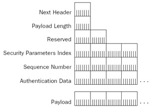
Figure 22-1: The IPSec Authentication header.
The AH consists of the following fields:
- Next HeaderA 1-byte field that is used to identify the next headerin the payload. This field uses the same values as the Protocol field in the IP header.
- Payload LengthA 1-byte field that specifies the number of bytes in the AH past the Payload Length field in 32-bit (4-byte) blocks, not counting the first2 blocks.
- ReservedA 2-byte field that is reserved and must be set to 0. The Reserved field is included in the Authentication Data field calculation, but otherwise ignored.
- Security Parameters IndexA 4-byte field that identifies, when used in combination with the Destination IP Address field and transform (AH), the specific SA for this datagram.
- Sequence NumberA 4-byte field that contains an incrementing counter value that starts at 0 when the SA is established. The first packet for the SA has asequence number of 1. The Sequence Number field provides antireplay protection because its value is protected by the ICV calculation. When the Sequence Number counts up to its maximum value (4,294,967,295 or 232 – 1), a new IPSec SA is established to keep the Sequence Number from repeating for an SA. When the new IPSec SA is established, the Sequence Number for the new SA starts at 0. If the Sequence Number for an incoming packet is too far out of sequence or if it matches a recently received sequence number, the packet is discarded.
- Authentication DataA variable-length field that contains the ICV calculation of the sender (the HMAC MD5 or HMAC SHA1 keyed hash value). The Authentication Data field provides data origin authentication and data integrity security services. The size of the Authentication Data field for both the HMAC MD5 and HMAC SHA1 is 12 bytes (96 bits) long. For an arbitrary ICV algorithm, the Authentication Data field size must be an integral number of 32-bit (4-byte) blocks. Padding is used if needed.
More Info AH is defined in RFC 2402, which can be found in the Rfc folder on the companion CD-ROM.
AH Transport Mode
IPSec has two main modes of operation: transport mode and tunnel mode.
- Transport mode is typically used for IPSec peers doing end-to-end security. Transport mode provides protection for upper-layer protocol data units (PDUs) by adding an extra header or trailer between the original IP datagram and its payload. Transport mode is typically used within an organization.
- Tunnel mode is typically used by network routers to protect IP datagrams when forwarding traffic over an insecure transit network. Tunnel mode provides protection for entire IP datagrams by encapsulating the IP datagram with an IPSec header/trailer and an additional IP header. Tunnel mode is typically used outside an organization when connecting sites across a public network such as the Internet.
Figure 22-2 shows AH transport mode for an IP datagram.
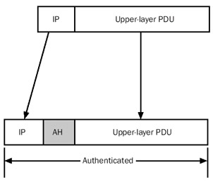
Figure 22-2: AH transport mode.
The AH header is added to the IP datagram just after the IP header. In the IP header, the Protocol field is set to 51 (0x33) to indicate that an AH is present. Other than changing the Protocol field, the original IP header is unmodified. Normal routers forward this traffic as any other IP packet. Firewalls, on the other hand, might need to be configured toallow the forwarding of IP protocol 51 traffic. The upper-layer PDU is also unmodified.Inserting an AH creates additional packet overhead, which lowers the effective maximum transmission unit (MTU) between the two endpoints. Calculating the ICV for the AH header also imposes additional processing overhead for each protected packet. Using network adapters that can perform cryptographic calculations in hardware can minimize this overhead.
For AH transport mode, the ICV calculation is performed over the following:
- All the fields in the IP header except those that are allowed to change in transit. These fields are the Type of Service (TOS), Flags, Fragment Offset, Time to Live (TTL), and Header Checksum, all of which are set to 0 for the ICV calculation. For source-routed IP traffic, the final destination IP address is predictable and the appropriate fields within the Loose Source Route and Strict Source Route options are allowed to change.
- All the fields in the AH (the Authentication Data field is set to 0).
- The upper-layer PDU.
For AH transport mode, the AH protects the IP header, except the fields that are allowed to change, and the upper-layer PDU of the original IP datagram.
Frame 11 of Network Monitor Capture 22-01 (in the Captures folder on the companion CD-ROM) provides an example of an AH-protected ICMP Echo message.
AH Tunnel Mode
Figure 22-3 shows AH tunnel mode for an IP datagram.

Figure 22-3: AH tunnel mode.
In AH tunnel mode, the entire original IP datagram is encapsulated with a new (outer) IP header and an AH. In the IP header, the Protocol field is set to 51 (0x33) to indicate that an AH is present. For tunnel mode, the original IP header and upper-layer PDU are unmodified.
The outer IP header is constructed from the configuration of the IPSec tunnel. For IPSec for the Windows Server 2003 family, the destination IP address in the outer header is configured in the Tunnel Setting tab from the properties of an IPSec rule using the IP Security Policies snap-in. The source IP address is the locally assigned IP address that is the best source to reach the tunnel destination address.
For AH tunnel mode, the ICV calculation is performed over the following:
- All the fields in the outer IP header except those that are allowed to change in transit (TOS, Flags, Fragment Offset, TTL, Header Checksum), all of which are set to 0 for the calculation.
- All the fields in the AH (the Authentication Data field is set to 0).
- The original IP packet.
For AH tunnel mode, the AH protects the entire original IP packet (both the IP header and the upper-layer PDU) at the expense of an additional outer IP header.
Encapsulating Security Payload (ESP) Header
Encapsulating Security Payload (ESP) is a header and trailer combination that provides data origin authentication, data integrity, replay protection, and data confidentiality for the ESP-encapsulated portion of the packet. Figure 22-4 shows the structure of the ESP header and trailer.
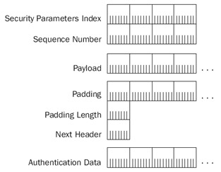
Figure 22-4: The IPSec Encapsulating Security Payload header and trailer.
The ESP header consists of the following fields:
- Security Parameters IndexA 4-byte field that identifies, when used in combination with the Destination IP Address field and transform (ESP), the spe-cific SA for this datagram.
- Sequence NumberA 4-byte field that is the same field is the Sequence Number field of the AH.
The ESP trailer consists of the following fields:
- PaddingA variable-length field that is used to pad the encrypted payload to an appropriate length (depending on the encryption algorithm used), align the ESP portion of the packet along 4-byte boundaries, or deliberately obscurethe encrypted payload's length.
- Padding LengthA 1-byte field that specifies the number of bytes in thePadding field.
- Next HeaderA 1-byte field used to identify the next header in the payload. This field uses the same values as the Protocol field in the IP header.
- Authentication DataA variable-length field that contains the ICV calculation of the sender (the HMAC MD5 or HMAC SHA1 value).
Because the use of a specific ICV algorithm is negotiated before data with an ESP header and trailer is sent, each peer knows the size of the Authentication Data portion of the ESP trailer and can determine the location of the end of the ESP-encapsulated payload.
Frame 11 of Network Monitor Capture 22-02 (in the Captures folder on the companion CD-ROM) provides an example of an ESP-protected payload. Network Monitor cannot interpret the encrypted portions of an ESP-protected packet.
ESP Transport Mode
Figure 22-5 shows ESP transport mode for an IP datagram.
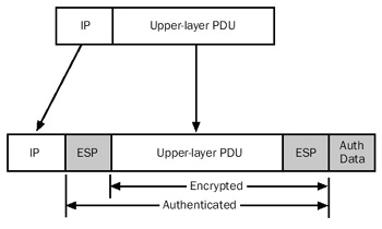
Figure 22-5: ESP transport mode.
For ESP transport mode, the ESP header is added to the IP datagram just after the IP header and the ESP trailer is added just after the upper-layer PDU. In the IP header, the Protocol field is set to 50 (0x32) to indicate that an ESP header is present. Other than changing the Protocol field, the original IP header is unmodified. Routers forward this traffic as any other IP packet. Firewalls, on the other hand, might need to be configured to allow the forwarding of IP protocol 50 traffic. The upper-layer PDU is also unmodified.
Like AH, inserting an ESP header and trailer creates additional packet overhead, which lowers the effective MTU between the two endpoints. Performing the data encryption and calculating the ICV for the ESP trailer imposes additional processing overhead for each protected packet. Using network adapters that can perform cryptographic calculations in hardware can minimize this overhead.
For ESP transport mode, the following portions of the packet are encrypted:
- The upper-layer PDU
- The Padding, Padding Length, and Next Header fields of the ESP trailer
For encryption algorithms such as DES that use CBC, there is an unencrypted fieldbetween the ESP header and the upper-layer PDU. This field is the IV for the CBC calculation performed at the receiver. This field cannot be encrypted because it is used to begin the decryption process. For DES and 3DES, the IV is 64 bits (8 bytes) long.
The inclusion of the IV as plaintext in the packet is not a security problem. The IV does not provide additional cryptographic strength, only a way to ensure that the encryption of the same block does not produce the same ciphertext. A malicious user might be able to view the IV, but without the encryption key, he or she cannot decrypt the ciphertext portion of the packet. To prevent a malicious user from modifying the IV and causing the receiver to produce garbled deciphered data, the IV is protected by the ICV.
For ESP transport mode, the ICV calculation is performed over the following:
- All the fields in the ESP header
- The upper-layer PDU (including the plaintext IV, if needed)
- All the fields in the ESP trailer except the Authentication Data field
For ESP transport mode, the ESP trailer does not provide protection for the IP header and the Authentication Data field of the ESP trailer. To obtain protection for these elements, use both AH and ESP, as shown in Figure 22-6.
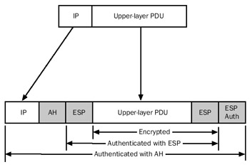
Figure 22-6: Using both AH and ESP to protect an IP packet.
In this situation, the ESP header and trailer wraps the upper-layer PDU, which then becomes the upper-layer PDU that is wrapped with an AH and the original IP header. Now the entire packet is protected (except the changeable fields in the IP header).
Frame 11 of Network Monitor Capture 22-03 (in the Captures folder on the companion CD-ROM) provides an example of an AH- and ESP-protected IP payload.
ESP Tunnel Mode
Figure 22-7 shows ESP tunnel mode for an IP datagram.
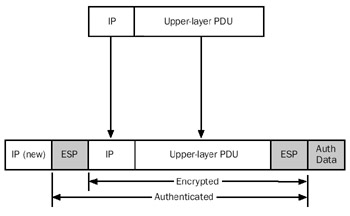
Figure 22-7: ESP tunnel mode.
In ESP tunnel mode, the entire original IP datagram is encapsulated with a new (outer) IP header and an ESP header and trailer. In the outer IP header, the Protocol field is set to 50 (0x32) to indicate that an ESP header is present. For tunnel mode, the original IP header and upper-layer PDU are unmodified. Like AH tunnel mode, the outer IP header is constructed from the configuration of the IPSec tunnel.
For ESP tunnel mode, the following portions of the packet are encrypted:
- The original IP datagram (IP header and upper-layer PDU)
- The Padding, Padding Length, and Next Header fields of the ESP trailer
For ESP tunnel mode, the ICV calculation is performed over the following:
- All the fields in the ESP header
- The original IP datagram (IP header and upper-layer PDU), including the plaintext IV, if needed
- All the fields in the ESP header except the Authentication Data field
For ESP tunnel mode, the ESP trailer does provide protection for the originalIP header and upper-layer PDU, but does not provide protection for the outer IP header and the Authentication Data field of the ESP trailer.
| More Info |
ESP is defined in RFC 2406, which can be found in the Rfc folder on the companion CD-ROM. |
Internet Key Exchange
The Internet Key Exchange (IKE) is a standard that defines a mechanism to establish SAs. IKE, described in RFC 2409, combines ISAKMP and the Oakley Key Determination Protocol.
IPSec uses the ISAKMP protocol to negotiate SAs. ISAKMP includes facilities to identify and authenticate peers, manage SAs, and exchange key material. ISAKMP is a framework for negotiating secure communications independent of specific key exchange protocols, encryption and integrity algorithms, and authentication methods.
To generate secret key material for secure communications, IKE uses the Oakley Key Determination protocol. Oakley is based on the Diffie-Hellman key exchange algorithm, which allows two peers to determine a secret key by exchanging unencrypted values over a public network. The shared secret key becomes keying material from which secret keys for HMAC or encryption algorithms are derived.
| More Info |
The details of the Diffie-Hellman algorithm and the Oakley protocol are outside the scope of this book, but they are described in RFC 2412. IKE isdefined in RFC 2407. Both of these RFCs can be found in the Rfc folder on the companion CD-ROM. |
ISAKMP Message Structure
ISAKMP messages are sent as the payload of UDP messages using UDP port 500. Figure 22-8 shows the format of an ISAKMP message.
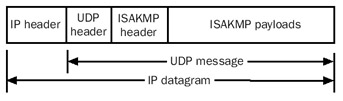
Figure 22-8: An ISAKMP message.
The ISAKMP message consists of an ISAKMP header and one or more ISAKMP payloads. The ISAKMP payloads contain negotiation information and are encrypted for most ISAKMP messages. The encryption protects the negotiation from being viewed by malicioususers who are capturing ISAKMP traffic. The encrypted portions of ISAKMP messages cannot be viewed with Network Monitor.
| More Info |
ISAKMP is defined in RFC 2408, which can be found in the Rfc folder on the companion CD-ROM. |
ISAKMP Header
The ISAKMP header is a standard header that is present for all ISAKMP messages and contains information about the message, including the type of packet. Figure 22-9 shows the format of the ISAKMP header.
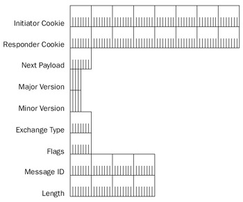
Figure 22-9: The ISAKMP header.
The fields in the ISAKMP header are defined as follows:
- Initiator CookieAn 8-byte field that is set to a nonzero random number chosen by the IPSec peer that initiated the SA, is performing a notification about an existing SA, or is deleting the SA.
- Responder CookieAn 8-byte field that is set to a nonzero random number chosen by the IPSec peer responding to the peer that initiated an SA.
- Next PayloadA 1-byte field that indicates the type of the payload that follows the ISAKMP header. Table 22-1 lists the payload types defined in RFC 2408.
Table 22-1: Values of the Next Payload Field Next Payload Value
Next Payload Type
0
None
1
SA
2
Proposal
3
Transform
4
Key Exchange
5
Identification
6
Certificate
7
Certificate Request
8
Hash
9
Signature
10
Nonce
11
Notification
12
Delete
13
Vendor ID
14–127
Reserved
128–255
Private Use
- Major VersionA 4-bit field that indicates the major version of the ISAKMP protocol for this message. This field must be set to 1 if the implementation complies with RFC 2408. ISAKMP messages with a higher supported major version number are discarded.
- Minor VersionA 4-bit field that indicates the minor version of the major version of the ISAKMP protocol for this message. This field must be set to 0 if the implementation complies with RFC 2408. ISAKMP messages with a higher supported minor version number are discarded, within the same supported major version.
- Exchange TypeA 1-byte field that indicates the type of ISAKMP exchange being performed for this ISAKMP message. The type of exchange dictates the structure and the order of ISAKMP payloads. Table 22-2 lists the exchange types defined in RFC 2408.
Table 22-2: Values of the Exchange Type Field Exchange Type Value
Exchange Type
0
None
1
Base
2
Identity Protection
3
Authentication Only
4
Aggressive
5
Informational
6–31
ISAKMP Future Use
32–127
DOI Specific Use
128–255
Private Use
- FlagsA 1-byte field containing ISAKMP flags that are set for this ISAKMP message. There are three flags defined in RFC 2408. The low-order bit (bit 0) is the Encryption bit, which indicates that the ISAKMP payloads are encrypted (when set to 1) or not encrypted (when set to 0). Encryption is done using the algorithm negotiated for the ISAKMP SA, which is identified by the combination of the Initiator Cookie and Responder Cookie fields. The next low-order bit (bit 1) is the Commit bit, which indicates that the key exchange is synchronized (when set to 1) or not synchronized (when set to 0). The Commit bit is used to ensure that the SA completes its negotiation before encrypted data is sent. The next low-order bit (bit 2) is the Authentication Only bit, which is used to indicate that the message either contains (when set to 1) or does not contain (when set to 0) the entire Notify payload of the informational exchange type and it has been authenticated but not encrypted.
- Message IDA 4-byte field that contains a unique identifier for the message. The Message ID is used to prevent collisions due to both IPSec peers attempting to simultaneously establish an IPSec SA. The Message ID field is set to 0 for the ISAKMP SA establishment.
- LengthA 4-byte field that indicates the length of the entire ISAKMP message.
SA Payload
The SA payload is used to indicate the domain of interpretation (DOI) and situation for the SA negotiation. The DOI is a set of definitions for payload formats, exchange types, and naming conventions for security-related information, such as the naming of policies and cryptographic algorithms. A situation is a set of information that identifies security services in the ISAKMP message. Figure 22-10 shows the format of the SA payload.
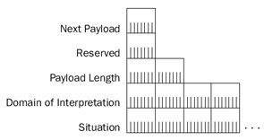
Figure 22-10: The SA payload.
The fields in the SA payload are defined as follows:
- Next PayloadA 1-byte field that indicates the next payload in the message. Next Payload is set to 0 for the last payload in the message. For the SA payload, the Next Payload field does not indicate the Proposal or Transform payloads because they are considered part of the SA payload.
- ReservedA 1-byte field set to 0.
- Payload LengthA 2-byte field that indicates the length of the payload. For the SA payload, the length includes the Proposal and Transform payloads.
- Domain of InterpretationA 4-byte field that indicates the DOI. For IPSec and ISAKMP, the DOI field is set to 1. RFC 2407 describes the IPSec DOI for ISAKMP.
- SituationA variable-length field that identifies the situation for the negotiation. For IPSec, the values of the Situation field are defined in RFC 2407. For example, the Situation field is set to 1 for SIT_IDENTITY_ONLY, a situation that specifies that the identity of the sending source is contained in an Identification payload. See section 4 of RFC 2407 for additional situation definitions.
Note The Next Payload, Reserved, and Payload Length fields are common to all ISAKMP payloads. Therefore, they are not described in the payload sections that follow unless there are additional considerations for their use.
Proposal Payload
The Proposal payload contains security parameter information that is used to negotiate the security settings for either an ISAKMP or IPSec SA. The Proposal payload contains proposal settings and then a series of one or more Transform payloads that contain the specific security settings for encryption and authentication algorithms for the SA. Figure 22-11 shows the format of the Proposal payload.
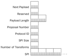
Figure 22-11: The Proposal payload.
The fields in the Proposal payload are defined as follows:
- Next PayloadFor the Proposal payload, the Next Payload field mustbe set to either 2 for additional Proposal payloads or 0 for no moreProposal payloads.
- Payload LengthFor the Proposal payload, the Payload Length fieldindicates the length of the entire Proposal payload, which includes the Transform payloads for this Proposal payload.
- Proposal #A 1-byte field that indicates the number of this proposal.
- Protocol-IDA 1-byte field that specifies the protocol identifier for the traffic to be secured. The values are the same as the Protocol field in the IP header. For example, 1 for ICMP, 6 for TCP, 17 for UDP, and so on.
- SPI SizeA 1-byte field that indicates the length of the SPI for the protocol indicated by the Protocol-ID field. If the protocol indicated by the Protocol-ID field does not use a SPI, it is set to 0.
- # of TransformsA 1-byte field that indicates the number of Transform payloads for this proposal.
- SPIA variable-size field that contains the SPI. This field is only present if the SPI Size field is greater than 0.
Transform Payload
The Transform payload contains information that identifies a specific security mechanism, or transform, that is proposed to secure future traffic. The Transform payload also contains SA attributes, as defined in RFC 2407 for the IPSec DOI. Figure 22-12 shows the Transform payload.
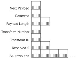
Figure 22-12: The Transform payload.
The fields in the Transform payload are defined as follows:
- Next PayloadFor the Transform payload, the Next Payload field must be set to either 3 for additional Transform payloads or 0 for no more Transform payloads for this proposal.
- Payload LengthFor the Transform payload, the Payload Length field indicates the length of the entire Transform payload, which includes the SA attributes for this Transform payload.
- Transform #A 1-byte field that indicates the number of this transform.
- Transform-IDA 1-byte field that indicates the Transform identifier for the protocol of the proposal. Transform IDs are defined in RFC 2407 for the IPSec DOI.
- Reserved2A 2-byte field that is set to 0.
- SA AttributesVariable-length fields that define the SA attributes for the transform. SA attributes are either in type-value or type-length (2 bytes)-value (TLV) format. In both cases, the Type field is 2 bytes in length. To distinguish type-value from TLV format, the high-order bit of the Attribute Type field is set to 1 for type-value format and 0 for TLV format. SA attributes for the IPSec DOI aredefined in section 4.5 of RFC 2407.
The following Network Monitor frame (Frame 1 of Capture 22-01 in the Captures folder on the companion CD-ROM) displays the relationship among the SA, Proposal, and Transform payloads, and the SA attributes within a Transform payload:
+ Frame: Base frame properties
+ ETHERNET: ETYPE = 0x0800 : Protocol = IP: DOD Internet Protocol
+ IP: ID = 0x261A; Proto = UDP; Len: 304
+ UDP: Src Port: ISAKMP, (500); Dst Port: ISAKMP (500); Length = 284 (0x11C)
 ISAKMP: Major Version: 1 Minor Version: 0 Length: 276
 ISAKMP: Initiator cookie = 18 DE 7D 29 15 E6 06 71
 ISAKMP: Responder cookie = 00 00 00 00 00 00 00 00
 ISAKMP: Next payload = Security Association
 ISAKMP: Major version = 1 (0x1)
 ISAKMP: Minor version = 0 (0x0)
 ISAKMP: Exchange type = Identity Protection
 + ISAKMP: Flags summary = 0 (0x0)
 ISAKMP: Message ID = 0 (0x0)
 ISAKMP: Length = 276 (0x114)
 ISAKMP: Payload type = Security Association
 ISAKMP: Next payload = Vendor ID
 ISAKMP: Reserved = 0 (0x0)
 ISAKMP: Payload length = 164 (0xA4)
 ISAKMP: DOI = 1 (0x1)
 ISAKMP: Situation = SIT_INDENTITY_ONLY
 ISAKMP: Payload type = Proposal
 ISAKMP: Next payload = None
 ISAKMP: Reserved = 0 (0x0)
 ISAKMP: Payload length = 152 (0x98)
 ISAKMP: Proposal number = 1 (0x1)
 ISAKMP: Protocol ID = 1 (0x1)
 ISAKMP: SPI size = 0 (0x0)
 ISAKMP: Number of transforms = 4 (0x4)
 ISAKMP: Payload type = Transform
 ISAKMP: Next payload = Transform
 ISAKMP: Reserved = 0 (0x0)
 ISAKMP: Payload length = 36 (0x24)
 ISAKMP: Transform number = 1 (0x1)
 ISAKMP: Transform ID = 1 (0x1)
 ISAKMP: Reserved = 0 (0x0)
 + ISAKMP: SA attribute = 80 01 00 05
 + ISAKMP: SA attribute = 80 02 00 02
 + ISAKMP: SA attribute = 80 04 00 02
 + ISAKMP: SA attribute = 80 03 00 01
 + ISAKMP: SA attribute = 80 0B 00 01
 + ISAKMP: SA attribute = 00 0C 00 04 00 00 70 80
 + ISAKMP: Payload type = Transform
 + ISAKMP: Payload type = Transform
 + ISAKMP: Payload type = Transform
 + ISAKMP: Payload type = Vendor ID
 + ISAKMP: Payload type = Vendor ID
 + ISAKMP: Payload type = Vendor ID
 + ISAKMP: Payload type = Vendor ID
Vendor ID Payload
The Vendor ID payload contains a string or number that either indicates a specific capability or is defined by a vendor so that an IPSec implementation can recognize an IPSec peer running the same implementation. IPSec peers are not required to run the same implementation or support the same capabilities, so the sending of Vendor ID payloads and the actions taken when they are received are optional. If a receiver recognizes the Vendor ID, it can make use of the capability or use private payloads, which use the Payload ID numbers 128 through 255. For vendor identification, the Vendor ID value must be unique and is typically a hash of well-known text chosen by the designers of an IPSec implementation. For capability identification, the Vendor ID value must be unique and is typically chosen by the designers of the IPSec capability.
Figure 22-13 shows the format of the Vendor ID payload.
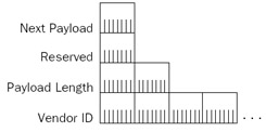
Figure 22-13: The Vendor ID payload.
The only field in the Vendor ID payload (besides the Next Header, Reserved, and Payload Length fields) is the Vendor ID field, a variable-length field that contains the Vendor ID value.
IPSec for the Windows Server 2003 family uses four different Vendor ID payloads:a Vendor ID payload to indicate a Microsoft IPSec peer, a Vendor ID payload to indicateNetwork Address Translator Traversal capability, a Vendor ID payload to indicate fragmentation support, and a Vendor ID payload to indicate support for network load balancing.
Nonce Payload
The Nonce payload contains a pseudorandom number that is used to ensure a liveexchange and provide replay protection. Nonces are also used to calculate hashes in other payloads. Figure 22-14 shows the format of the Nonce payload.
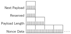
Figure 22-14: The Nonce payload.
The only field in the Nonce payload (besides the Next Header, Reserved, and Payload Length fields) is the Nonce Data field, a variable-length field that contains the pseudorandom number determined by the sender of the ISAKMP message.
Key Exchange Payload
The Key Exchange payload contains information pertaining to the key exchange process. The key exchange process supported by IPSec for the Windows Server 2003 family is Diffie-Hellman. With Diffie-Hellman, two IPSec peers exchange key values that are sent in plaintext. From the key values, each IPSec peer calculates the same private key. What is interesting about the Diffie-Hellman exchange is that a malicious user between the IPSec peers can view the exchanged key values, but cannot easily calculate the sameresult as the IPSec peers. Figure 22-15 shows the format of the Key Exchange payload.
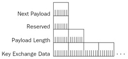
Figure 22-15: The Key Exchange payload.
The only field in the Key Exchange payload (besides the Next Header, Reserved, and Payload Length fields) is the Key Exchange Data field, a variable-length field that contains the key exchange value determined by the sender of the ISAKMP message.
Notification Payload
The Notification payload is used to transmit control information, such as an error condition, to an IPSec peer. A single ISAKMP message can contain multiple Notification payloads. For Notification payloads within a main mode message, the initiator and responder cookies identify the negotiation. Figure 22-16 shows the format of the Notification payload.
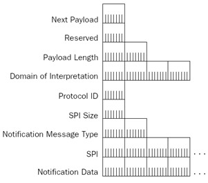
Figure 22-16: The Notification payload.
The fields in the Notification payload are defined as follows:
- Domain of InterpretationA 4-byte field that identifies the DOI for the notification. For the ISAKMP DOI, the value is 0. For the IPSec DOI, the value is 1.
- Protocol-IDA 1-byte value that indicates the protocol to which the notification applies.
- SPI SizeA 1-byte field that indicates the length of the SPI field. For ISAKMP, the security identifier is the initiator/responder cookie pair. Therefore, theSPI Size field is set to 16 and the SPI field contains the initiator/responder cookie pair.
- Notify Message TypeA 2-byte field that specifies the type of notification message.
- SPIA variable-length field that specifies the SPI for the notification.
- Notification DataA variable-length field that contains additional information or text for the notification message indicated by the Notify Message Type field.
Table 22-3 lists some of the notification error messages specified in RFC 2408. For a complete list, see section 3.14.1 of RFC 2408.
|
Notification Message Type Value |
Notification Message |
|---|---|
|
1 |
INVALID-PAYLOAD-TYPE |
|
2 |
DOI-NOT-SUPPORTED |
|
3 |
SITUATION-NOT-SUPPORTED |
|
4 |
INVALID-COOKIE |
|
5 |
INVALID-MAJOR-VERSION |
|
6 |
INVALID-MINOR-VERSION |
Table 22-4 lists some of the notification status messages specified in RFC 2408.
|
Notification Message Type Value |
Notification Message |
|---|---|
|
16384 |
CONNECTED |
|
16385–24575 |
RESERVED (Future Use) |
|
24576–32767 |
DOI-specific codes |
|
32768–40959 |
Private Use |
|
40960–65535 |
RESERVED (Future Use) |
Delete Payload
The Delete payload is used to inform an IPSec peer that an SA for a specific protocol has been deleted. The receiver should remove its corresponding SA. IPSec for the Windows Server 2003 family now supports verification of Delete payloads. If an ISAKMP message with a Delete payload is received, the receiver acknowledges it. If an acknowledgment is not received, the Delete payload is resent. Figure 22-17 shows the format of the Delete payload.
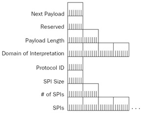
Figure 22-17: The Delete payload.
The fields in the Delete payload are defined as follows:
- Domain of InterpretationA 4-byte field that identifies the DOI. The DOI is 0 for ISAKMP and 1 for IPSec.
- Protocol-IDA 1-byte field that identifies the protocol for the SA that wasdeleted. The Protocol-ID indicates ISAKMP for main mode SA deletions and ESP or AH for quick mode SA deletions.
- SPI SizeA 1-byte field that indicates the length of the SPI field. For the ISAKMP protocol, the SPI is the initiator/responder cookie pair.
- # of SPIsA 2-byte field that indicates the number of SPIs in this Delete payload.
- Security Parameter Index(es)A variable-length field that identifies the SAs to delete. All of the SPIs have the same length, as indicated with the SPI Size field.
Identification Payload
The Identification payload is used to convey identification information and authenticate an IPSec peer.
Figure 22-18 shows the format of the Identification payload.
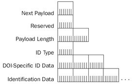
Figure 22-18: The Identification payload.
The fields in the Identification payload are defined as follows:
- ID TypeA 1-byte field that indicates the type of identification.
- DOI Specific ID DataA 3-byte field that contains DOI-specific data. Ifnot used, this is set to 0.
- Identification DataA variable-length field that contains identityinformation.
Hash Payload
The Hash payload contains a hash value that is a result of a hash function computed over a set of fields or other parameters. The Hash payload can be used to provide integrity or authentication of negotiating peers. Figure 22-19 shows the format of the Hash payload.
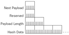
Figure 22-19: The Hash payload.
The only field in the Hash payload (besides the Next Header, Reserved, and Payload Length fields) is the Hash Data field, a variable-length field that contains the hash value. Both IPSec peers must agree to the set of fields or other parameters over which the hash is calculated.
Certificate Request Payload
The Certificate Request payload is used to request certificates from an IPSec peer. After receipt of an ISAKMP message with a Certificate Request payload, an IPSec peer must send a cer tificate or certificates based on the contents of the Certificate Request payload. Figure 22-20 shows the format of the Certificate Request payload.
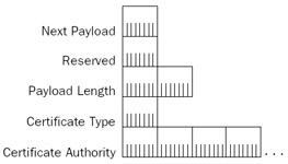
Figure 22-20: The Certificate Request payload.
The fields in the Certificate Request payload are defined as follows:
- Certificate TypeA 1-byte field that indicates the type of the certificaterequested. Table 22-5 lists the certificate types defined in RFC 2408.
Table 22-5: Certificate Type Values Certificate Type Value
Certificate Type
0
None
1
PKCS #7 wrapped X.509 certificate
2
PGP Certificate
3
DNS Signed Key
4
X.509 Certificate: Signature
5
X.509 Certificate: Key Exchange
6
Kerberos Tokens
7
Certificate Revocation List (CRL)
8
Authority Revocation List (ARL)
9
SPKI Certificate
10
X.509 Certificate: Attribute
11–255
Reserved
- Certificate AuthorityA variable-length field that contains an acceptable certification authority (CA) for the indicated type of certificate. For example, for an X.509 certificate, the distinguished name of the issuing CA is used. If there is no specific CA required by the sending IPSec peer, this field is not present.
Certificate Payload
The Certificate payload is used by an IPSec peer when sending its certificate. This is typically done during the authentication phase of main mode negotiation. Figure 22-21 shows the format of the Certificate payload.
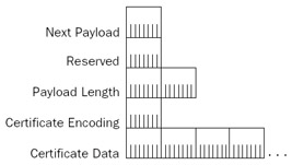
Figure 22-21: The Certificate payload.
The fields in the Certificate payload are defined as follows:
- Certificate EncodingA 1-byte field that indicates the method for encoding the certificate information in the Certificate Data field. Table 22-5 lists the values of the Certificate Encoding field defined in RFC 2408. The same values for the Certificate Type field of the Certificate Request payload are used for the Certificate Encoding field in the Certificate payload.
- Certificate DataA variable-length field that contains the encoding of the certificate using the encoding method indicated in the Certificate Encoding field.
Signature Payload
The Signature payload is used to send digital signatures calculated over a set of fields or parameters. The Signature payload provides data integrity and nonrepudiation services during the authentication phase of main mode negotiation. Figure 22-22 shows the format of the Signature payload.
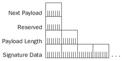
Figure 22-22: The Signature payload.
The only field in the Signature payload (besides the Next Header, Reserved, and Payload Length fields) is the Signature Data field, a variable-length field that contains the digital signature value. Both IPSec peers must agree on the set of fields and parameters over which the digital signature is calculated.
Main Mode Negotiation
Oakley main mode negotiation is used to determine encryption key material and security protection for use in protecting subsequent main mode or quick mode communications. Main mode negotiation occurs in the following steps:
- Negotiation of protection suites
- A Diffie-Hellman exchange
- Authentication
Note IPSec for the Windows Server 2003 family does not support aggressive mode negotiation.
Main mode negotiation consists of six ISAKMP messages: three sent by the initiator and three sent by the responder. Messages 1 and 2 are for the negotiation of protection suites. Messages 3 and 4 are for the Diffie-Hellman exchange. Messages 3 through 6 can be used for authentication. The specific contents of messages 3 through 6 depend on the authentication method.
Negotiation of Protection Suites
The first message in an IKE negotiation is sent by the initiator and contains the following payloads:
- SAThe SA payload contains a Proposal payload, which contains a series of Transform payloads, each of which contains a series of security attributes. The SA payload is the set of protection suites (which include allowed encryption algorithms, hash algorithms, authentication methods, and Diffie-Hellman Oakley groups) that are acceptable to the initiator. This set of protection suites is configured in the Key Exchange Security Methods dialog box in the IP Security Management snap-in. The authentication methods are configured in theAuthentication Methods tab from the properties of an IPSec rule.
- Vendor IDThe Vendor ID payloads contain vendor identification and capability indication.
The second message in an IKE negotiation is sent by the responder and contains the following payloads:
- SAThe SA payload contains a Proposal payload, which contains a single Transform payload corresponding to the protection suite that was offered by the initiator in the first message and is acceptable to the responder. Because the responder might select the first transform in the first message that is acceptable, it is a good practice to configure the key exchange security settings in order of most to least secure.
- Vendor IDThe Vendor ID payloads contain vendor identification and capability indication.
Table 22-6 lists the protection suite attributes that are supported by IPSec for theWindows Server 2003 family.
|
Attribute |
Attribute Value |
|---|---|
|
Encryption algorithm |
DES, 3DES |
|
Integrity algorithm |
MD5, SHA-1 |
|
Authentication method |
Kerberos, preshared key, certificate |
|
Diffie-Hellman group |
Group 1 (768-bit), Group 2 (1024-bit), 2048-bit |
Key Exchange and Authentication
IPSec for the Windows Server 2003 family supports three methods of authentication:
- Kerberos
- Certificates
- Preshared key
Unlike Point-to-Point Protocol (PPP) authentication for dial-up or virtual private network (VPN) connections, which authenticates the user using the computer at the time of the authentication negotiation, IPSec authentication authenticates only the computer at the time of the negotiation.
Kerberos Authentication
Kerberos authentication is the default authentication method. It is designed for usebetween computers in an Active Directory domain. Kerberos authentication for IPSec main mode is based on the Generic Security Service (GSS) API IKE authentication method,described in the Internet draft entitled "A GSS-API Authentication Method for IKE," which can be found in the Ietf Drafts folder on the companion CD-ROM.
The third message for a Kerberos-authenticated main mode negotiation, sent by the initiator, contains the following payloads:
- Key ExchangeThe Key Exchange payload contains Diffie-Hellman private key determination information as derived by the initiator.
- NonceThe Nonce payload contains a pseudorandom number derived by the initiator.
- Kerberos TokenThe Kerberos Token payload contains the initiator's Kerberos token to be validated by the responder.
- NAT-DiscoveryTwo NAT-Discovery payloads contain hashes of the initiator's source and destination addresses and ports. For more information, see the section "IPSec NAT Traversal," later in this chapter.
The fourth message for a Kerberos-authenticated main mode negotiation, sent by the responder, contains the following payloads:
- Key ExchangeThe Key Exchange payload contains Diffie-Hellman private key determination information as derived by the responder. The initiator and responder use both sets of Diffie-Hellman key material and derive the same private key.
- NonceThe Nonce payload contains a pseudorandom number derived by the responder.
- Kerberos TokenThe Kerberos Token payload contains the responder's Kerberos token to be validated by the initiator.
- NAT-DiscoveryTwo NAT-Discovery payloads contain hashes of the responder's source and destination addresses and ports.
The fifth message for a Kerberos-authenticated main mode negotiation, which is sent by the initiator and encrypted, contains the following payloads:
- IdentificationThe Identification payload contains information that iden-tifies the initiator.
- HashThe Hash payload contains a hash result calculated by the initiator.
The sixth message for a Kerberos-authenticated main mode negotiation, which is sent by the responder and encrypted, contains the following payloads:
- IdentificationThe Identification payload contains information that identifies the responder.
- HashThe Hash payload contains a hash result calculated by theresponder.
Kerberos authentication is successful when each peer verifies the other peer's Kerberos token and hash value.
The hash calculation is performed over the following values:
- The Diffie-Hellman key exchange values sent by both the initiator andresponder
- The initiator and responder cookies
- The ISAKMP payloads of main mode message 2
- The identity name string for the IPSec peer
- The IPSec peer's Kerberos token
Network Monitor Capture 22-02 (in the Captures folder on the companion CD-ROM) provides an example of Kerberos authentication.
Certificate Authentication
Certificate authentication involves the exchange of public key certificates for validation. IPSec for the Windows Server 2003 family supports X.509 version 3 certificates and certificate authentication must be configured in the Authentication Method tab for a rule within an IPSec policy. When configuring certificate authentication, the list of trusted root CAs is specified. You do not necessarily specify the root CA of the issuing CA of the certificate that will be sent, only the root CAs for the issuing CAs of the certificates that are acceptable to receive. Internally, IPSec for the Windows Server 2003 family uses the CryptoAPI to perform various certificate retrieval, verification, and digital signature creation functions.
The third message for a certificate-authenticated main mode negotiation, sent by the initiator, contains the following payloads:
- Key ExchangeThe Key Exchange payload contains Diffie-Hellman private key determination information as derived by the initiator.
- NonceThe Nonce payload contains a pseudorandom number derived by the initiator.
- NAT DiscoveryTwo NAT-Discovery payloads contain hashes of the initiator's source and destination addresses and ports.
The fourth message for a certificate-authenticated main mode negotiation, sent by the responder, contains the following payloads:
- Key ExchangeThe Key Exchange payload contains Diffie-Hellman private key determination information as derived by the responder. The initiator and responder use both sets of Diffie-Hellman key material and derive the same private key.
- NonceThe Nonce payload contains a pseudorandom number derived by the responder.
- Certificate RequestThe Certificate Request payload contains a list of trusted root CAs from which a certificate is acceptable to the responder.
- NAT DiscoveryTwo NAT-Discovery payloads contain hashes of the responder's source and destination addresses and ports.
The fifth message for a certificate-authenticated main mode negotiation, which is sent by the initiator and is encrypted, contains the following payloads:
- IdentificationThe Identification payload contains information that identifies the initiator.
- CertificateThe Certificate payload contains a certificate acceptable to the responder.
- Certificate RequestThe Certificate Request payload contains a list of trusted root CAs from which a certificate is acceptable to the initiator.
- SignatureThe Signature payload contains a digital signature, providing proof that the initiator has access to the private key of the sent certificate. The digital signature is calculated over the Diffie-Hellman keys, the initiator and responder cookies, the SA, and the initiator's identity.
The sixth message for a certificate-authenticated main mode negotiation, which is sent by the responder and is encrypted, contains the following payloads:
- IdentificationThe Identification payload contains information that identifies the responder.
- CertificateThe Certificate payload contains a certificate acceptable to the initiator.
- SignatureThe Signature payload contains a digital signature, providing proof that the responder has access to the private key of the sent certificate. The digital signature is calculated over the Diffie-Hellman keys, the initiator and responder cookies, the SA, and the responder's identity.
Certificate authentication is successful when each peer verifies the other peer's certificate and digital signature.
For Layer Two Tunneling Protocol with IPSec (L2TP/IPSec) connections, you cannot configure the list of trusted root CAs. The list of trusted root CAs is based on the root CAs for the issuing CAs for certificates installed in the Local Computer certificate store. To have a successful L2TP/IPSec connection, each IPSec peer must have an installed computer certificate that was issued by an issuing CA of a trusted root CA that also issued computer certificates to the other IPSec peer.
Network Monitor Capture 22-04 (in the Captures folder on the companion CD-ROM) provides an example of certificate authentication.
Certificate Revocation Checking
By default, IPSec for the Windows Server 2003 family does not perform certificate revocation checking on the sent certificate or the chain of certificates from the issuing CA to the root CA of the issuing CA. Certificate revocation checking is done by verifying that each certificate in the chain is not on a certificate revocation list (CRL) that wascreated and published by the issuing CA. To enable certificate revocation checking, use the following registry setting:
StrongCrlCheck
Location:
HKEY_LOCAL_MACHINESYSTEMCurrentControlSetServicesPolicyAgentOakley
Data type: REG_DWORD
Valid range: 0-2
Default: 0
Present by default: No
Set StrongCrlCheck to 1 to fail certificate revocation checking if the certificate has been revoked by verifying its revoked status with the CRL. If the CRL distribution point is not available on the network or the creator of the CRL did not issue the certificate, the certificate is assumed to be valid. Set StrongCrlCheck to 2 to fail the certification validation for any certificate revocation check error. In this case, the CRL distribution point must be reachable on the network, and it must verify that it issued the certificate and that it is not revoked. By default, StrongCrlCheck is set to 0, indicating that no certificate revocation checking is done.
If you change this value, you must stop and start the IPSec services either through the Services snap-in or by running the net stop policyagent and net start policyagent commands at a command prompt. If the computer is running Routing and Remote Access, you should stop the Routing and Remote Access service before you stop the IPSec services and start the Routing and Remote Access service after you start the IPSec services.
Preshared Key Authentication
Preshared key authentication involves the exchange of the knowledge of a manually configured preshared key. IPSec for the Windows Server 2003 family includes preshared key authentication to adhere to the IPSec standards and provide interoperability with other IPSec implementations that do not support Kerberos or certificate authentication.
A preshared key is configured in the Authentication Methods tab in the properties of an IPSec rule in the IP Security Policies snap-in. Because the preshared key is visible to all those who can view the IPSec policy settings (users with local or domain administrator privileges), preshared key authentication is not a secure authentication method and is not recommended for use in production environments.
The third message for a preshared key-authenticated main mode negotiation, sent by the initiator, contains the following payloads:
- Key ExchangeThe Key Exchange payload contains Diffie-Hellman private key determination information as derived by the initiator.
- NonceThe Nonce payload contains a pseudorandom number derived by the initiator.
- NAT DiscoveryTwo NAT-Discovery payloads contain hashes of the initiator's source and destination addresses and ports.
The fourth message for a preshared key-authenticated main mode negotiation, sent by the responder, contains the following payloads:
- Key ExchangeThe Key Exchange payload contains Diffie-Hellman private key determination information as derived by the responder. The initiator and responder use both sets of Diffie-Hellman key material and derive the same private key.
- NonceThe Nonce payload contains a pseudorandom number derived by the responder.
- NAT DiscoveryTwo NAT-Discovery payloads contain hashes of the responder's source and destination addresses and ports.
The fifth message for a preshared key-authenticated main mode negotiation, which is sent by the initiator and is encrypted, contains the following payloads:
- IdentificationThe Identification payload contains information that identifies the initiator.
- HashThe Hash payload contains a hash result calculated by the initiator that incorporates the preshared key.
The sixth message for a certificate-authenticated main mode negotiation, which is sent by the responder and is encrypted, contains the following payloads:
- IdentificationThe Identification payload contains information that identifies the responder.
- HashThe Hash payload contains a hash result calculated by the responder that incorporates the preshared key.
Preshared key authentication is successful when each peer verifies the other peer's hash.
Network Monitor Capture 22-05 (in the Captures folder on the companionCD-ROM) provides an example of preshared key authentication.
Quick Mode Negotiation
When the main mode negotiation is complete, each IPSec peer has selected a specific set of cryptographic algorithms for securing main mode and quick mode messages,exchanged key information to derive a shared secret key, and performed authentication. Before secure data is sent, a quick mode negotiation must occur to determine the type of traffic to be secured and how it will be secured. A quick mode negotiation is also done when a quick mode SA expires. Quick mode messages are ISAKMP messages that are encrypted using the ISAKMP SA. The result of a quick mode negotiation is two IPSec SAs: one for inbound traffic and one for outbound traffic.
Quick mode negotiation for IPSec for the Windows Server 2003 family consists of four ISAKMP Messages. The first Quick Mode ISAKMP message, sent by the initiator, contains the following payloads:
- SAThe SA payload contains a list of proposals and encryption and hashing algorithms for how to secure the traffic (AH vs. ESP, DES vs. 3DES, and MD5 vs. SHA1) and a description of the traffic that is protected (IP addresses, IP Protocol IDs, TCP ports, UDP ports, etc.). These settings are a combination of the filter action, filter list, and tunnel settings for the properties of a rule in the IP Security Policies snap-in.
- IdentificationThe Identification payload contains a description of the traffic to be secured.
- NonceThe Nonce payload contains a pseudorandom number to be used in subsequent hash calculations.
The second quick mode ISAKMP message, sent by the responder, contains the following payloads:
- SAThe SA payload contains a Proposal payload, which contains a single Transform payload corresponding to the protection suite that was offered by the initiator in the first quick mode message and is acceptable to the responder for the traffic to be secured.
- IdentificationThe Identification payload contains a description of the traffic to be secured.
- NonceThe Nonce payload contains a pseudorandom number to be used in subsequent hash calculations.
The second message has the Commit flag in the ISAKMP header set.
The third quick mode ISAKMP message, sent by the initiator, contains the following payload:
- HashThe Hash payload contains a hash value to provide verification and replay protection.
The fourth quick mode ISAKMP message, sent by the responder, contains the following payload:
- NotificationThe Notification payload contains the Notify Message Type set to 16384 (the CONNECTED status message), indicating that the SA negotiation is complete.
The setting of the Commit bit in quick mode message 2 and the sending of the CONNECTED status message in quick mode message 4 are not required by the ISAKMPor IKE standards. IPSec for the Windows Server 2003 family uses this facility toprevent the initiator from sending IPSec-protected packets to the responder before theresponder is ready to receive them.
Retransmit Behavior
For main mode negotiations, the retransmit behavior of the initiator is thefollowing:
- Send main mode message 1. Wait 1 second for a response.
- If a response is not received, retransmit main mode message 1 and wait 2 seconds for a response. If unsecured communication is allowed, unsecured traffic can be sent. Even though unsecured traffic is sent, the initiator continues to attempt a main mode negotiation.
- Retransmit main mode message 1 and wait 4 seconds for a response.
- Retransmit main mode message 1 and wait 8 seconds for a response.
- Retransmit main mode message 1 and wait 16 seconds for a response.
- Retransmit main mode message 1 and wait 32 seconds for a response.
- Abandon main mode negotiation.
It takes 63 seconds for a main mode negotiation to fail. This retransmit behavior is part of the IKE standard. For unsecured traffic, it takes 3 seconds before the initiator sends unsecured traffic.
For quick mode negotiations, the retransmit behavior for either IPSec peer is thefollowing:
- Send quick mode message 1 and wait 1 second for a response.
- Retransmit quick mode message 1 and wait 2 seconds for a response.
- Retransmit quick mode message 1 and wait 4 seconds for a response.
- Retransmit quick mode message 1 and wait 8 seconds for a response.
- Retransmit quick mode message 1 and wait 16 seconds for a response.
- Retransmit quick mode message 1 and wait 32 seconds for a response.
- If this quick mode negotiation is not the first quick mode for the current main mode (a rekey), restart quick mode negotiation. Otherwise, abandon quick mode negotiation.
It takes 63 seconds for a quick mode negotiation to fail. This retransmit behavior is part of the IKE standard. The initiator of the main mode negotiation does the initial quick mode negotiation. After a successful quick mode negotiation, either IPSec peer can initiate a new quick mode negotiation.
IPSec NAT Traversal
IPSec was designed to provide end-to-end security for two computers located in the same address domain. If two computers are located in different address domains, such as private IP addresses used on a home network and public IP addresses used on the Internet, then the addresses must be translated for communication to occur. The translation of addresses and TCP or UDP ports for network address translation to connect users to the Internet invalidates the security services of IPSec. Specifically, address and port translation causes the following problems for ESP-based IPSec traffic:
- For ESP-protected packets, the TCP and UDP ports are encrypted and therefore cannot be translated.
- ISAKMP messages calculate hashes and signatures based on SA information, which includes IP addresses. Translating the IP address invalidates the hash or signature.
Network Address Translators (NATs) are very prevalent in today's public address-starved Internet. To allow IKE negotiation and ESP-encapsulated packets to work over NATs, IPSec for the Windows Server 2003 family supports IPSec NAT traversal (NAT-T) asdescribed in version 2 of the Internet drafts titled "UDP Encapsulation of IPSec Packets" and "Negotiation of NAT-Traversal in the IKE." These drafts are included in the Ietf Drafts folder on the companion CD-ROM. NAT-T is especially useful when making L2TP/IPSec connections from a VPN client that is behind a NAT.
NAT-T consists of the following elements used during main mode:
- The sending of a NAT-T capability Vendor ID payload, which indicates that the IPSec peer is capable of performing NAT traversal. The NAT-T capability Vendor ID payload is sent in main mode messages 1 and 2.
- The sending of a NAT-Discovery (NAT-D) payload that contains a hash of the original packet's address and port number so that the receiving node can determine whether a NAT changed the IP address or port. Two separate NAT-Dpayloads are included in main mode messages 3 and 4. One NAT-D payload is for the destination address and port and the other is for the source address and port.
A receiving IPSec peer validates both NAT-D payloads. If either does not validate correctly, then an intermediate NAT is present and NAT-T quick mode options are used. In addition, a new IKE message header format is defined that uses UDP port 4500. The NAT- T IKE header contains a new Non-ESP Marker field that allows the receiver to distinguish between UDP-encapsulated ESP-protected traffic and NAT-T IKE messages.
NAT-T consists of the following elements used during quick mode:
- The inclusion of either UDP-Encapsulated-Tunnel or UDP-Encapsulated-Transport encapsulation mode in the proposals of the SA payload of quick mode message 1.
- The sending of a NAT-Original Address (NAT-OA) payload to indicate the original source address to the IPSec peer. The NAT-Original Address (NAT-OA) payload is included in quick mode messages 1 and 2.
NAT-T for IKE and ESP consists of the following elements used when sending data:
- The encapsulation of an ESP-protected payload with a UDP header that uses the same UDP ports as ISAKMP. By including a UDP header, the NAT can change the UDP port number and it is not part of the ESP-encrypted payload or the ISAKMP Hash or Signature payload calculation.
- If the IPSec peer is behind a NAT, it sends a periodic NAT-Keepalive packet, which is a single-byte (0xFF) UDP message that uses the ISAKMP UDP ports. The NAT-Keepalive packet is used to persist the NAT's UDP port mappingfor ISAKMP and UDP-encapsulated ESP traffic. Without the use of the NAT-Keepalive packet, the UDP port mapping in the NAT eventually times out and packets from the IPSec peer are silently discarded. The IKE module on thereceiving IPSec peer immediately discards the NAT-Keepalive packets.
The combination of these elements and additional processing steps allows:
- ISAKMP to detect a NAT-T-capable IPSec peer and the presence of NATsbetween the peers.
- ISAKMP to complete main mode and quick mode negotiation despite the NAT's presence.
- ESP-protected traffic to traverse a NAT.
Summary
IPSec is the standard method of providing security services for IP packets. The two protocols used for IP packet protection are AH and ESP. AH provides data origin authentication, data integrity, and replay protection for the entire IP packet, except for the fields in the IP header that are allowed to change. ESP provides data origin authentication, data integrity, data confidentiality, and replay protection for the ESP-encapsulated payload. To negotiate SAs for sending secure traffic, IPSec uses IKE, a combination of ISAKMP and the Oakley Key Determination Protocol. ISAKMP messages contain many types of payloads to exchange information during SA negotiation. Main mode negotiation is used to establish the ISAKMP SA, which is used to protect future main mode and all quick mode negotiations. Quick mode negotiation is used to establish the IPSec SA to protect data. IPSec NAT-T is a set of ISAKMP payloads and changes to the ISAKMP protocol that provides ESP protection for IPSec peers located behind a NAT.
Part I - The Network Interface Layer
- Local Area Network (LAN) Technologies
- Wide Area Network (WAN) Technologies
- Address Resolution Protocol (ARP)
- Point-to-Point Protocol (PPP)
Part II - Internet Layer Protocols
- Internet Protocol (IP) Basics
- Internet Protocol (IP) Addressing
- Internet Protocol (IP) Routing
- Internet Control Message Protocol (ICMP)
- Internet Group Management Protocol (IGMP)
- Internet Protocol Version 6 (IPv6)
Part III - Transport Layer Protocols
- User Datagram Protocol
- Transmission Control Protocol (TCP) Basics
- Transmission Control Protocol (TCP) Connections
- Transmission Control Protocol (TCP) Data Flow
- Transmission Control Protocol (TCP) Retransmission and Time-Out
Part IV - Application Layer Protocols and Services
- Dynamic Host Configuration Protocol (DHCP) Server Service
- Domain Name System (DNS)
- Windows Internet Name Service (WINS)
- File and Printer Sharing
- RADIUS and Internet Authentication Service
- Internet Information Services (IIS) and the Internet Protocols
- Internet Protocol Security (IPSec)
- Virtual Private Networks (VPNs)
EAN: N/A
Pages: 216
