Internet Protocol (IP) Routing
Overview
To troubleshoot TCP/IP connectivity problems, it is important to understand how packets are forwarded from a source to a destination node on an Internet Protocol (IP) internetwork. For data to be exchanged between any two nodes, each must be reachable from the other. For universal reachability, a forwarding path between any two nodes must exist in both directions. The forwarding paths are determined by the contents of local IP routing tables and the nature of the IP routing infrastructure.
Introduction to IP Routing
IP routing is the process of forwarding unicast IP traffic to its destination in an IP internetwork with an arbitrary topology. Specifically, IP routing is the process of forwarding packets from the sending host through a series of intermediate routers. To facilitate the forwarding process, the sending host and each router make a forwarding decision based on the contents of their local IP routing table. For hosts and routers running a member of the Microsoft Windows Server 2003 family, the IP routing table entries are created based on the TCP/IP configuration, static routing table entries, Internet Control Message Protocol (ICMP) Redirect, or routing protocols.
For discussion in this chapter, a node is a network device running the TCP/IP protocol, a host is a TCP/IP node that does not have routing capability, and a router (or gateway) is a TCP/IP node that does have routing capability. Both hosts and routers are considered nodes.
Direct and Indirect Deliveries
When forwarding an IP datagram, the sending host performs either a direct or indirect delivery to the destination. If the destination is directly reachable—on a directly attached network segment—the forwarding node performs a direct delivery by resolving the destination node's media access control (MAC) address and sending the frame to the destination. If the destination is not directly reachable—not on a directly attached network segment—the host uses its IP routing table to determine an intermediate router's next-hop IP address. The forwarding node performs an indirect delivery by resolving the intermediate router's MAC address and sending the frame to the intermediate router.
The IP routing process is a series of direct and indirect deliveries, as shown in Figure 7-1. For Host A and Host B, on the same network segment, Host A performs a direct delivery when sending packets to Host B. For Host A and Host C, on different network segments separated by a single IP router, Host A performs an indirect delivery to the router. The router then performs a direct delivery to Host C.
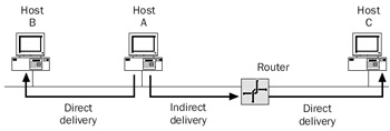
Figure 7-1: IP forwarding showing direct and indirect delivery.
For more details on the behavior of the Address Resolution Protocol (ARP) during direct and indirect deliveries, see Chapter 3, "Address Resolution Protocol (ARP)."
Types of Links
The IP forwarding process and IP routing table entries vary depending on the type of link over which the packet is being forwarded. The following are the three types of links:
- Broadcast
- Point-to-point
- Nonbroadcast multiple access
Broadcast
The broadcast link type is characterized by its ability to have more than two nodes on the same network segment, and each frame sent is received at the Network Interface Layer by all of the network segment's nodes. Ethernet, Token Ring, and Fiber Distributed Data Interface (FDDI) are examples of broadcast links. In each case, one of the possible multiple nodes on the network segment must be distinguished using a Network Interface Layer address. For Ethernet, Token Ring, and FDDI, the Network Interface Layer address is the destination MAC address. ARP is used to resolve the destination MAC address for a given next-hop IP address.
The broadcast link type supports the ability to multicast to a group of hosts on the network segment or to broadcast to all hosts on the segment. Routing protocols such as Routing Information Protocol (RIP) or Open Shortest Path First (OSPF) use the ability to multicast to propagate routing information. RIP routers can use either subnet broadcastsor the 224.0.0.9 multicast address. OSPF routers use the multicast addresses of 224.0.0.5 and 224.0.0.6. Figure 7-2 shows Ethernet, an example of a broadcast link.

Figure 7-2: A broadcast link such as Ethernet where a single packet is received by multiple nodes.
To forward an IP datagram on a broadcast network, knowledge of the next-hopIP address is required.
Point to Point
The point-to-point link type is characterized by its ability to support only two IP nodes. Examples of point-to-point links are typical leased-line and circuit-switched wide area network (WAN) links such as analog phone lines, T-Carrier (including T1/E1 and T3/E3), and Integrated Services Digital Network (ISDN). For point-to-point links, there is only one possible node that receives the forwarded IP datagram. Therefore, ARP is not used to resolve a Network Interface Layer address and the next-hop IP address is irrelevant.
Routing protocols such as RIP and OSPF work over point-to-point links without modification. For broadcast RIP announcements, the two routers' IP addresses on the point-to-point link network segment must be from the same IP network ID. If the IP addresses of the two routers' interfaces on the point-to-point link are from different network IDs, the receiving router does not process broadcast RIP requests or announcements. If this is the case, use RIP version 2 and multicast announcements.
For OSPF, the router interfaces are configured for the OSPF point-to-point network type. In this configuration, OSPF routers always use the multicast address of 224.0.0.5. Figure 7-3 shows a leased-line connection between two routers using T1, an example of a point-to-point link.
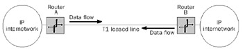
Figure 7-3: A point-to-point link such as a T1 leased line contains a maximum oftwo nodes.
Non Broadcast Multiple Access
The non-broadcast multiple access (NBMA) link type is characterized by its ability to support more than two IP nodes; however, this link type cannot multicast or broadcast. Examples of NBMA links are packet-switched WAN technologies such as X.25, frame relay, and Asynchronous Transfer Mode (ATM). In each of these technologies, a single WAN adapter can support multiple virtual circuits. However, with the exception ofrecent developments in frame relay, NBMA links have no capability to send a single packet that is copied to all the configured virtual circuits.
For X.25, frame relay, and ATM adapters operating in NBMA mode, the next-hop IP address is relevant. However, because there is no multicast or broadcast facility, ARP is not used. Inverse ARP can be used to discover the IP addresses of the routers on the other end of the virtual circuit. The next-hop IP address from the route in the routing table is mapped to the appropriate virtual circuit identifier using a table maintained by the adapter.
For RIP and OSPF operation over an NBMA network, instead of broadcasting or multicasting, RIP or OSPF neighbors are configured. Each neighbor is a unicast location to which RIP or OSPF traffic is sent. Figure 7-4 shows a frame relay spoke and hub configuration, an example of an NBMA link.
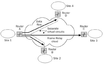
Figure 7-4: An NBMA link such as frame relay, where a single interface supports multiple virtual circuits without a broadcast facility.
For X.25, frame relay, and ATM adapters operating in multi- or subinterface mode, each virtual circuit is represented as a separate logical adapter. Each logical adapter is the equivalent of a point-to-point adapter. RIP and OSPF are configured the same way as a point-to-point link.
The IP Routing Table
The IP routing table is a database of routes present in memory on all IP nodes. Each entry, or route, in the routing table contains forwarding information for a range of destination IP addresses. The level of detail for destination IP addresses—the number of routes in the routing table—depends on whether the IP node is a host or a router. Typically, IP hosts have few entries and IP routers have many.
It is common on IP internetworks to configure IP hosts with a default gateway. This configuration creates a default route that effectively summarizes all destinations. For IP routers, it is common for the routing table to contain an entry for every reachable network on the IP internetwork, although route summarization and default routing are also commonly used.
In each case, the IP routing table's purpose is to yield two values for the destination IP address of each packet being forwarded:
- The next-hop interfaceThe next-hop interface is the representation of a physical or logical device over which the IP datagram is forwarded.
- The next-hop IP addressThe next-hop IP address is the IP address of the node to which the IP datagram is forwarded. For direct deliveries, the next-hop IP address is the destination IP address of the IP datagram being forwarded. For indirect deliveries, the next-hop IP address is the IP address of a directly reachable intermediate router to which the IP datagram is being forwarded.
Structure
A route in the IP routing table contains enough information to identify the destination, identify the next-hop interface and IP address, and distinguish the best route to use when multiple routes to the destination are found.
Typical IP routing tables contain the following fields for each route:
- DestinationUsed in conjunction with the Network Mask field, this field isa representation of the range of IP addresses that is reachable with this route. The Destination field can be an IP network ID (classful, subnet, supernet) or an IP address.
- Network MaskThe network mask is the bit mask that is used to determine the significant bits in the Destination field. A 1 bit in the Network Mask field identifies a bit that must match the Destination field for this route. A 0 bit in the Network Mask field indicates a bit that does not have to match the Destination field. The Network Mask field must consist of a series of contiguous 1 bits followed by a series of contiguous 0 bits. The Destination and the Network Mask fields define a range of IP addresses. An IP datagram with a destination IP address within the range matches the route.
To determine whether the destination IP address of an IP datagram being forwarded matches a route, the destination IP address is bit-wise logically ANDed with the Network Mask. The result is compared with the value of the Destination field for the route. If they match, the route matches the destination IP address for the packet and the corresponding next-hop IP address is used.
Due to the ANDing process used between the Network Mask field and the Destination field, the Destination field cannot be more specific than the Network Mask field. In binary terms, the Destination field cannot have bits set to 1 in bit positions where the Network Mask field has bits set to 0. Because the logical ANDing of a 1 and a 0 is always a 0, the ANDing of the Network Mask field with any IP address never results in a match to the Destination field. This is a useless route because it never matches any destination. Computers running a member of the Windows Server 2003 family do not allow such a route to be added to the IP routing table. To test whether a destination and network mask combination is invalid, perform a bit-wise logical AND of the destination and the network mask. If the result is not the destination, the combination is invalid.
- Next-Hop IP AddressIndicates the IP address to which the IP datagram is to be forwarded if it matches this route. The Next-Hop IP Address field's value is relevant for broadcast or NBMA links and irrelevant for point-to-point links. For routes of directly attached network segments, the Next-Hop IP Address field can be set to the IP address of that network segment's interface. This is the behavior of the IP routing table for the Windows Server 2003 family.
- InterfaceThis is the designation of the logical or physical interface used when forwarding IP datagrams using this route. The Interface field's value can be a logical name or the IP address assigned to the interface. The IP routing table for the Windows Server 2003 family uses the IP address assigned to the interface.
- MetricThis field indicates the route's cost and is used by the route determination process to choose among multiple routes with the same destinationand network mask. When there are multiple routes that match the same des-tination and network mask, the route with the lowest metric is used. The Metric field is commonly used to reflect the hop count—the number of routers tothe destination—although routing protocols such as OSPF use customizable link costs that take into account the bandwidth, delay, and physical linkcosts when calculating the metric.
Types of Routes
A route in the IP routing table is one of the following types (in order of most to least specific):
- Host routeA route to a specific IP address; therefore, the network mask is 255.255.255.255 (/32). Host routes allow you to customize IP routing on a per IP address basis. Host routes are commonly used to specify a more optimal route to specific hosts on a remote subnet.
- Network ID routeA route for classful, classless, subnet, and supernetted destinations. The network mask for a network ID route is somewhere between 128.0.0.0 (/1) and 255.255.255.254 (/31).
Each network ID route can be either a directly attached network ID route or a remote network ID route. A directly attached network ID route is a route fora network segment on which the router has an interface. Routes for directly attached network IDs might not have a value for the next-hop IP address. A remote network ID is a network ID that is available across another router.For remote network ID routes, the next-hop IP address is an intermediate router's IP address. The next-hop IP address must be directly reachableusing the interface in the Interface field.
- Default routeA route to all destinations, used when no other host route or network ID route matching the destination is found. The default route has a destination of 0.0.0.0 and a network mask of 0.0.0.0 (/0) and is sometimesexpressed as 0/0. Notice that the default route is a matching route for any destination IP address (any IP address AND 0.0.0.0 is 0.0.0.0). A default route is used to summarize all possible destinations. The default gateway configured on an IP host creates a default route in the IP routing table. For routers, a default route is used to summarize all destinations, and is typically used for static routing and summarizing all the destinations of a large IP internetwork such as the Internet.
Route Determination Process
For any IP datagram being forwarded, a single route in the routing table must be chosen to determine the next-hop interface and IP address for the forwarding process. To determine the single best route for forwarding, IP uses the following process:
- For each route in the IP routing table, determine which routes match the destination IP address in the IP datagram by performing a bit-wise logical ANDbetween the destination IP address and the network mask, and comparing the result to the value of the Destination field. If they match, mark the route as a matching route.
- From the routes that matched the destination, determine which have the largest number of 1 bits in the Network Mask field. The route(s) with the largest number of 1 bits are the route(s) that most closely matched the destination IP address. This is known as the longest match or closest match paradigm. The longest match is the most specific route to the destination node. Note that for thedefault route, there are no 1 bits in the Network Mask field; however, it is a matching route.
- From the list of longest matching routes, determine which has the lowest metric.
- From the list of longest matching routes with the lowest metric, the router is free to choose from the remaining routes.
The end result of the route determination process is the choice of a single route thatis the most specific route to the destination with the lowest metric. The single route chosen yields the next-hop IP address and the interface over which to forward the IP datagram.
If no matching route is found, IP indicates a routing error. For a sending host, an internal IP routing error informs the upper layer protocol. For a router, the IP datagram is discarded and an ICMP Destination Unreachable-Host Unreachable message is sent back to the sending host.
The closest matching route process favors routes matching the destination in the following order:
- Host routeFor a host route, all 32 bits match the destination IP address.
- Subnet routeFor a route representing a subnetted network ID, all the class-based network bits and all the subnet bits match the destination IP address.
- Class-based network routeFor a route representing a class-based network ID, all class-based network bits match the destination IP address.
- Supernet or summarized routeFor a route representing a supernetted (Classless Interdomain Routing [CIDR]) or summarized route, all the bits in the summarized network ID match the destination IP address.
- Default routeFor the default route, none of the bits matches the destination IP address.
IP Routing Table for the Windows Server 2003 Family
The IP routing table for the Windows Server 2003 family (for a single interface host with the IP address 131.107.140.89, subnet mask 255.255.240.0, and default gateway 131.107.128.1), as displayed with the route print command, is shown here:
F:>route print
===========================================================================
Interface List
0x1 ........................... MS TCP Loopback interface
0x10003 ...00 04 5a 56 0f 5b ...... Linksys LNE100TX Fast Ethernet
Adapter(LNE100TX v4) #2
===========================================================================
===========================================================================
Active Routes:
 Network Destination Netmask Gateway Interface Metric
 0.0.0.0 0.0.0.0 131.107.128.1 131.107.140.89 20
 127.0.0.0 255.0.0.0 127.0.0.1 127.0.0.1 1
 131.107.128.0 255.255.240.0 131.107.140.89 131.107.140.89 20
 131.107.140.89 255.255.255.255 127.0.0.1 127.0.0.1 20
 131.107.255.255 255.255.255.255 131.107.140.89 131.107.140.89 20
 224.0.0.0 240.0.0.0 131.107.140.89 131.107.140.89 20
 255.255.255.255 255.255.255.255 131.107.140.89 131.107.140.89 1
Default Gateway: 131.107.128.1
===========================================================================
Persistent Routes:
 None
This example of an IP routing table for the Windows Server 2003 family consists of the following routes:
- Default route (0.0.0.0 with 0.0.0.0 or 0/0)
The closest matching route when there are no other matches. If the default route is chosen, the packet is forwarded to the default gateway's IP address (131.107.128.1) using the interface assigned to the IP address 131.107.140.89.
- Loopback network route (127.0.0.0 with 255.0.0.0 or 127.0.0.0/8)
Matches any IP address in the range 127.0.0.0 through 127.255.255.255. AllIP addresses beginning with 127 are reserved for loopback. All IP datagrams addressed in this range are forwarded to the reserved loopback address 127.0.0.1 using the loopback interface.
- Directly attached network route (131.107.128.0 with 255.255.240.0 or 131.107.128.0/20)
A route to the locally attached subnet. When this route is chosen, the IP datagram is forwarded to the destination IP address using the interface assigned the IP address 131.107.140.89.
- Local host route (131.107.140.89 with 255.255.255.255 or 131.107.140.89/32)
A host route for the assigned IP address. All traffic addressed to the local host IP address is forwarded to the reserved loopback address 127.0.0.1 using the loopback interface.
- All-subnets-directed broadcast route (131.107.255.255 with 255.255.255.255 or 131.107.255.255/32)
A host route for the all-subnets-directed broadcast address for the class B network ID 131.107.0.0/16. Packets addressed to the all-subnets-directed broadcast address are sent as MAC-level broadcasts, using the interface assigned the IP address of 131.107.140.89. An all-subnets-directed broadcast route is present only if the locally attached network segment is subnetted. For more information on the all-subnets-directed broadcast, see Chapter 6, "Internet Protocol (IP)Addressing."
- Multicast addresses route (224.0.0.0 with 240.0.0.0 or 224.0.0.0/4)
Used to match all class D addresses reserved for IP multicast traffic. IP multicast packets are sent as MAC-level multicasts, using the interfaceassigned the IP address of 131.107.140.89.
- Limited broadcast route (255.255.255.255 with 255.255.255.255 or 255.255.255.255/32)
A host route for the limited broadcast address. Datagrams addressed to the limited broadcast address are sent as MAC-level broadcasts using the interfaceassigned the IP address 131.107.140.89.
These are the routes in the IP routing table created based on the common configuration of an IP address, a subnet mask, and a default gateway. Additional routes can be added through static routes, the receipt of ICMP Redirect messages, or a routing protocol.
The IP routing table for the Windows Server 2003 family differs from the IP routing table for Microsoft Windows 2000 in the following ways:
- The routing metric for interface and default gateway-based routes is by default set by the TCP/IP protocol based on the speed of the interface. In this example, the routing metric of 20 indicates a 100-Mbps Ethernet interface. Automaticdetermination of interface-based routing metrics can be disabled through the advanced properties of the TCP/IP protocol.
- The netmask for the multicast route is 240.0.0.0, rather than 224.0.0.0. Thisnew netmask is a better match for the class D range of addresses defined for multicast addresses.
Multihomed Nodes
For multihomed nodes—nodes with more than one IP address—additional entries for the local host route, the directly attached network ID route, the multicast route, and the limited broadcast address are present for each IP address added. An example is shown here:
F:>route print
===========================================================================
Interface List
0x1 ........................... MS TCP Loopback interface
0x10003 ...00 04 5a 56 0f 5b ...... Linksys LNE100TX Fast Ethernet Adapter
(LN0TX v4) #2
0x10004 ...00 04 5a 56 0f 62 ...... Linksys LNE100TX Fast Ethernet Adapter
(LN0TX v4)
===========================================================================
===========================================================================
Active Routes:
 Network Destination Netmask Gateway Interface Metric
 0.0.0.0 0.0.0.0 131.107.128.1 131.107.140.89 20
 10.117.94.0 255.255.255.0 10.117.94.30 10.117.94.30 30
 10.117.94.30 255.255.255.255 127.0.0.1 127.0.0.1 30
 10.255.255.255 255.255.255.255 10.117.94.30 10.117.94.30 30
 127.0.0.0 255.0.0.0 127.0.0.1 127.0.0.1 1
 131.107.128.0 255.255.240.0 131.107.140.89 131.107.140.89 20
 131.107.140.89 255.255.255.255 127.0.0.1 127.0.0.1 20
 131.107.255.255 255.255.255.255 131.107.140.89 131.107.140.89 20
 224.0.0.0 240.0.0.0 10.117.94.30 10.117.94.30 30
 224.0.0.0 240.0.0.0 131.107.140.89 131.107.140.89 20
 255.255.255.255 255.255.255.255 10.117.94.30 10.117.94.30 1
 255.255.255.255 255.255.255.255 131.107.140.89 131.107.140.89 1
Default Gateway: 131.107.128.1
===========================================================================
Persistent Routes:
 None
In this example, the Linksys LNE100TX Fast Ethernet Adapter #2 is configured with the IP address 131.107.140.89, the subnet mask 255.255.240.0, and the default gateway of 131.107.128.1. The Linksys LNE100TX Fast Ethernet Adapter is configured with the IP address 10.117.94.30 and the subnet mask 255.255.255.0. The Linksys LNE100TX Fast Ethernet Adapter is plugged into a 10-Mbps Ethernet hub, and the routes corresponding to this interface have an automatically determined routing metric of 30. The Linksys LNE100TX Fast Ethernet Adapter #2 is plugged into a 100-Mbps Ethernet hub, and the routes corresponding to this interface have an automatically determined routing metric of 20.
Maintaining the IP Routing Table
You maintain the IP routing table for the Windows Server 2003 family with the Route command-line utility. With Route, you can view the routing table and add, change, and delete routes. The IP routing table is stored in random access memory (RAM) and is not preserved when the computer is restarted. It rebuilds a default routing table based on the TCP/IP configuration when TCP/IP is initialized.
To make additional static routes persistent so that they are always added when TCP/IP is initialized, add the routes using the route add command with the -p option. Routes added with the -p option are stored in the registry under the following key:
HKEY_LOCAL_MACHINESYSTEMCurrentControlSetServicesTCPIP
ParametersPersistentRoutes
For a computer running a member of the Windows Server 2003 family and the Routing and Remote Access service, the IP routing table also can be maintained from the Routing and Remote Access administrative tool. Use shortcut menu options available from the IP RoutingStatic Routes object to view the IP routing table and add static routes. Figure 7-5 shows the IP routing table as it appears in the Routing and Remote Access administrative tool.
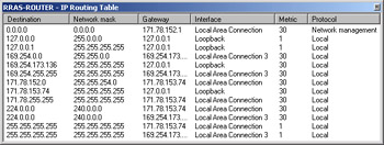
Figure 7-5: The IP routing table as viewed from the Routing and Remote Access administrative tool.
The IP Routing Process for the Windows Server 2003 Family
The IP routing process for the Windows Server 2003 family is as follows:
- Perform the route determination process previously described to choose a single route that is the closest match to the destination and has the lowest metric.
- From the chosen route, examine the gateway and interface IP addresses.
- If the gateway IP address is the same as the interface IP address, set the next-hop IP address to the destination IP address in the IP datagram being forwarded.
- If the gateway IP address is not the same as the interface IP address, set the next-hop IP address to the gateway IP address.
The result of the IP routing process for the Windows Server 2003 family is theIP address of the interface over which the packet is to be forwarded (the Interface field's IP address) and the next-hop IP address (either the IP datagram's destination IP address or the Gateway field's value). This result is then passed to the ARP module to determine the following:
- For unicast IP traffic sent over broadcast links, the unicast MAC address of the node using the next-hop IP address
- For multicast IP traffic sent over broadcast links, the multicast MAC address corresponding to the multicast IP address
- For broadcast IP traffic sent over broadcast links, the MAC-level broadcast address
For more details on how ARP resolves the unicast MAC address of the node to which the datagram is being forwarded, see Chapter 3, "Address Resolution Protocol (ARP)."
Examples of Route Determination for the Windows Server 2003 Family
A host running a member of the Windows Server 2003 family has the following IP routing table:
F:>route print
===========================================================================
Interface List
0x1 ........................... MS TCP Loopback interface
0x10003 ...00 04 5a 56 0f 5b ...... Linksys LNE100TX Fast Ethernet
Adapter(LNE100TX v4) #2
===========================================================================
===========================================================================
Active Routes:
Network Destination Netmask Gateway Interface Metric
 0.0.0.0 0.0.0.0 172.16.1.1 172.16.1.99 20
 127.0.0.0 255.0.0.0 127.0.0.1 127.0.0.1 1
 172.16.1.0 255.255.255.0 172.16.1.99 172.16.1.99 20
 172.16.1.99 255.255.255.255 127.0.0.1 127.0.0.1 20
 172.16.255.255 255.255.255.255 172.16.1.99 172.16.1.99 20
 224.0.0.0 240.0.0.0 172.16.1.99 172.16.1.99 20
 255.255.255.255 255.255.255.255 172.16.1.99 172.16.1.99 1
Default Gateway: 172.16.1.1
===========================================================================
Persistent Routes:
 None
The following are examples of how this routing table is used to determine the next-hop IP address and interface for several different destinations:
- Unicast destination 172.16.1.47
When sending traffic to the unicast destination IP address 172.16.1.47 (local subnet traffic), the matching routes are the default route (0.0.0.0 with 0.0.0.0) and the local subnet route (172.16.1.0 with 255.255.255.0). Because the local subnet route is a closer match to the destination IP address (the first 24 bits in the Network Destination matched rather than 0 bits for the default route), the directly attached network ID route is chosen. Because the Gateway and Interface fields are set to the same value, the next-hop IP address for the datagram is set to 172.16.1.47. The IP datagram, the next-hop IP address (172.16.1.47), and the interface (172.16.1.99) are passed to ARP to perform a direct delivery.
- Unicast destination 192.168.0.79
When sending traffic to the unicast destination IP address 192.168.0.79 (remote traffic), the only matching route is the default route (0.0.0.0 with 0.0.0.0). Because the Gateway and Interface fields are different, the next-hop IP address for the datagram is set to 172.16.1.1. The IP datagram, the next-hop IP address (172.16.1.1), and the interface (172.16.1.99) are passed to ARP to performan indirect delivery.
- Multicast destination 224.0.0.1
When sending traffic to the multicast destination IP address 224.0.0.1, the matching routes are the default route (0.0.0.0 with 0.0.0.0) and the multicast route (224.0.0.0 with 240.0.0.0). Because the multicast route is a closer match to the destination IP address (the first 4 bits in the Network Destination matched rather than 0 bits for the default route), the multicast route is chosen. Because the Gateway and Interface fields are set to the same value, the next-hop IP address for the datagram is set to 224.0.0.1. The IP datagram, the next-hop IP address (224.0.0.1), and the interface (172.16.1.99) are passed to the ARP module. However, for multicast traffic, the corresponding Network Interface Layer address for 224.0.0.1 isdetermined (for Ethernet and FDDI, the MAC address is 01-00-5E-00-00-01)and the packet is sent without performing address resolution.
- Subnet broadcast destination 172.16.1.255
When sending traffic to the subnet broadcast destination IP address 172.16.1.255, the matching routes are the default route (0.0.0.0 with 0.0.0.0) and the local subnet route (172.16.1.0 with 255.255.255.0). Because the local subnet route is a closer match to the destination IP address (24 bits in the Network Destination matched rather than 0 bits for the default route), the directly attached network ID route is chosen. Because the Gateway and Interface fields are set to the same value, the next-hop IP address for the datagram is set to 172.16.1.255. The IP datagram, the next-hop IP address (172.16.1.255), and the interface (172.16.1.99) are passed to the ARP module. However, for broadcast traffic, the corresponding Network Interface Layer address for broadcast traffic is determined (for Ethernet, Token Ring, and FDDI, the MAC address is FF-FF-FF-FF-FF-FF) and the packet is sent without performing address resolution.
- Unicast destination 172.16.1.99
When sending traffic to the unicast destination IP address 172.16.1.99, thematching routes are the default route (0.0.0.0 with 0.0.0.0), the local subnetroute (172.16.1.0 with 255.255.255.0), and the local host route (172.16.1.99 with 255.255.255.255). Because the local host route is the closest possible match to the destination IP address (all 32 bits in the Network Destination matched rather than 24 bits for the local subnet route and 0 bits for the default route), the local host route is chosen. The next-hop address is 127.0.0.1 and the next-hop interface is the loopback adapter. The packet is forwarded to the internal loopback adapter without performing address resolution.
IP Routing from Sending Host to Destination
To fully understand IP routing, we must examine the series of forwarding processes that occur at the sending host, the intermediate routers, and the destination host. The following processes assume an IP header without Loose Route, Strict Route, or Record Route IP options.
Sending Host Forwarding Process
When the sending host (a computer running a member of the Windows Server 2003 family) forwards an IP datagram, IP performs the following steps:
- The Time to Live (TTL) is set to either the default value or the value specified by an upper layer protocol.
- The destination IP address is passed to the IP routing process for the Windows Server 2003 family, which determines the next-hop interface and IP address.If no route is chosen, IP indicates a routing error to the upper layer protocol.
- IP passes the IP datagram, the next-hop IP address, and the next-hop interface to ARP.
- ARP resolves the next-hop IP address to a unicast MAC address for the indicated interface. For a direct delivery, ARP resolves the destination's MAC address. For an indirect delivery, ARP resolves the intermediate router's MAC address. Once ARP determines the MAC address for the next-hop IP address, it calls NDISSend() to send the frame using the appropriate network adapter.
Note This sending process assumes that there are no Internet Protocol Security (IPSec) rules that either modify the packet or prevent its sending and that there are no Routing and Remote Access service IP filters that prevent its sending.
IP Router Forwarding Process
When a computer running a member of the Windows Server 2003 family acting as an IP router receives an IP datagram, IP performs the following steps:
- IP verifies the IP header checksum. It runs the checksum calculation and compares the result with the value stored in the IP datagram's Header Checksum field. If the result does not match the value of the Header Checksum field, IP silently discards the IP datagram.
- IP checks the IP Version field. If the IP version does not equal 4, IP silently discards the IP datagram.
- If the IP packet contains either a loose or strict source routing header and the DisableIPSourceRouting registry setting is set to 1 (the default), the packet is silently discarded.
- If the IP packet is a fragment, the Routing and Remote Access service is running, and fragmentation checking is enabled on the interface on which the packet was received, the packet is silently discarded. Fragmentation checking is enabled in the General tab from the properties of an interface in the IP RoutingGeneral node in the Routing and Remote Access administrative tool.
- IP checks the destination IP address in the IP datagram.
- If the destination address in the datagram is an IP multicast address and multicast forwarding is enabled, IP forwards the datagram appropriately. For more information on this process, see Chapter 9, "Internet Group Management Protocol (IGMP)."
- If the destination address corresponds to local host traffic (it is an IP address of a router interface or a broadcast address of a locally attached network), IP processes the datagram as the destination host.
- If the destination IP address in the datagram is a unicast address that is not a local host IP address, IP decrements the TTL value in the IP header.
- If the TTL is 0 (or less), IP submits the IP header and the first 8 bytes of the IP payload to ICMP with an error indication. IP then discards the IP datagram. ICMP includes the IP header and the first 8 bytes of the IP payload as the payload of an ICMP Time Expired-TTL Expired message that is sent back to the sending host.
- If the TTL is 1 or greater after decrementing, IP updates the TTL field with its new value, recalculates the IP header checksum, and updates the Header Checksum field's value.
- IP passes the value of the destination IP address in the IP datagram to the IP route determination process. If no route is found, IP submits the IP header and the IP payload's first 8 bytes to ICMP with an error indication. IP then discards the IP datagram. ICMP includes the IP header and the first 8 bytes of the IP payload as the payload of an ICMP Destination Unreachable-Host Unreachable message that is sent back to the sending host.
- If a route is found, IP passes the modified IP datagram, the next-hop interface, and the next-hop IP address to ARP.
- ARP resolves the next-hop IP address to a unicast MAC address for the indicated interface. For a direct delivery, ARP resolves the destination's MAC address. For an indirect delivery, ARP resolves the intermediate router's MAC address. Once the MAC address for the next-hop IP address is determined, ARP calls NDISSend( ) to send the frame using the appropriate network adapter.
This forwarding process is repeated at each intermediate router in the path between the sending host and the destination host.
| Note |
This forwarding process assumes that there are no IPSec rules thateither modify the packet or prevent its forwarding and that there are no Routing and Remote Access service IP filters that prevent its forwarding. |
Destination Host Receiving Process
When the final intermediate router performs a direct delivery to the destination host, IP on the destination host performs the following steps:
- IP verifies the IP header checksum. It runs the checksum calculation and compares the result with the value stored in the IP datagram's Header Checksum field. If the result does not match the Header Checksum field's value, IP silently discards the datagram.
- IP checks the IP Version field. If the IP version does not equal 4, IP silently discards the datagram.
- IP checks the destination IP address in the datagram.
- If the destination address in the datagram is a unicast address that is not a local host IP address, IP silently discards the datagram.
- If the destination IP address corresponds to local host traffic (it is an IP address of a host interface or a broadcast address of a locally attached network) or an IP multicast address, IP checks the Protocol field.
- If the Protocol field's value corresponds to an upper layer protocol that is being used on the host, IP passes the IP payload to the appropriate upper layer protocol.
- If the Protocol field's value does not correspond to an upper layer protocol that is being used on the host, IP forwards the IP header and the first 8 bytes of the IP payload to ICMP with an error indication. IP then discards the IP datagram. ICMP includes the IP header and the first 8 bytes of the IP payload as the payload of an ICMP Destination Unreachable-Protocol Unreachablemessage that is sent back to the sending host.
- If the IP payload is a TCP segment, IP hands the TCP segment to TCP. After TCP verifies the TCP checksum, it checks the destination port in the TCP header. If the value of the Destination Port field corresponds to an application running on the host, the TCP segment is processed further. If the value of the Destination Port field does not correspond to an application running on the host, a TCP Connection Reset segment is sent back to the sending host. For more information on TCP connections, see Chapter 13, "Transmission Control Protocol (TCP) Connections."
- If the IP payload is a User Datagram Protocol (UDP) message, IP hands the UDP message to UDP. After UDP verifies the UDP checksum, it checks the Destination Port field in the UDP header. If the value of the Destination Port field corresponds to an application running on the host, the UDP message is processed further. If the value of the Destination Port field does not correspondto an application running on the host, UDP submits the IP header and the first 8 bytes of the IP payload to ICMP with an error indication. UDP then discards the UDP message. ICMP includes the IP header and the first 8 bytes of the IP payload as the payload of an ICMP Destination Unreachable-Port Unreachable message that is sent back to the sending host.
Note This receiving process assumes that there are no IPSec rules, TCP/IPprotocol filters, or Routing and Remote Access service IP filters that prevent its reception.
IP Routing Infrastructure Overview
For the successful delivery of IP datagrams to an arbitrary location in an IP internetwork, you must employ an IP routing infrastructure. Hosts and routers must have the supporting routes in their routing table to forward unicast traffic to any reachable location. Typically for hosts, all destinations are either directly reachable or reachable through a default route pointing to their default gateway. Routers, however, have either explicit routes for each network segment in the IP internetwork, summarized or aggregated routes, or a default route. The combination of the host's routing table entries and the routers comprise the IP routing infrastructure.
The type of IP routing infrastructure that you deploy can have the following characteristics:
- Single-path vs. multipath
- Class-based vs. classless
- Flat vs. hierarchical
- Static vs. dynamic
- Single vs. multiple autonomous systems
Single Path vs Multipath
For a single-path routing infrastructure, IP traffic can only travel a single path between any source and any destination. Single-path infrastructures are simple but they are intolerant of network faults. A downed link or a downed router creates physically separate portions of the internetwork that are unreachable for the duration of the fault.
For a multipath routing infrastructure, IP traffic can travel different paths between any source and destination. Typically, a multipath environment forwards IP traffic along a single path until the network topology changes. When coupled with dynamic routing, multipath routing infrastructures can be fault-tolerant. Multipath infrastructures are more complex to plan and implement and there is a possibility that, either because of misconfiguration or a period when the internetwork topology is changing, a routing loop can form. A routing loop is a path through the routing infrastructure that loops back on itself, which occurs when routers forward traffic in a loop that does not include the network segment of the destination. Traffic caught in a routing loop is forwarded between the routers of the loop until the TTL in the IP header becomes 0. Figure 7-6 shows a routing loop created by misconfiguration of the default route (0/0) among three routers (Router B, Router D, and Router C).
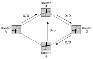
Figure 7-6: A default routing loop among Router B, Router D, and Router C.
One way to detect routing loops in your internetwork is to use the Ping command-line utility with the -i option set to 255. The -i option sets the TTL in the ICMP Echo message. If the Ping utility displays "TTL Expired In Transit," there is a good chance you have a routing loop. To ensure that you do have a routing loop, use the Tracert command-line utility to trace the route to the destination. In the Tracert display, look for a set of router IP addresses or names that repeats.
Class Based vs Classless
Your routing infrastructure can be either class-based or classless. Although originally a class-based routing infrastructure, address allocation and routing on the modern Internet is classless.
Class-Based Routing
Class-based routing is the determination of the network ID based on the IP address classes. Class-based routing protocols such as RIP version 1 do not advertise a subnet mask when advertising routes. You can subnet with class-based routing protocols; however, there are limitations to the types of addresses and configurations that are permitted.
For example, when subnetting a class-based network ID, all of the subnets of the class-based network ID must be contiguous. Class-based routing protocols do not advertise the subnets of a class-based network ID on network segments that are not a subnet of the class-based network ID. Rather, on network segments that are not a subnet of the class-based network ID, they advertise the summarized class-based network ID. Class-based IP routers summarize the subnets of a class-based network ID by advertising the class-based network ID. Because of this behavior, all subnets must be contiguous. Two different subnets of the same class-based network ID in different parts of the IP internetwork (discontiguous subnets) both separately advertise the summarized class-based network ID. With two routes to the same class-based network ID, routers use the one with the lowest metric. Regardless of which route is chosen, because of proximity to the advertising router, incorrect routing occurs. The locations on both subnets are not reachable by all hosts on the IP internetwork. Because routes learned from neighboring routers are received without a network mask, the class-based router must assume the subnet mask based on the following:
- If the route fits the class (there are no 1 bits in the host ID portion of the class-based network ID), the class-based default subnet mask is assumed. For example, if the route 195.241.4.0 is received, the network mask of 255.255.255.0 is assumed. This assumption assigns the incorrect mask for CIDR blocks and other usesof aggregated routes. For example, for the CIDR block 195.241.8.0/21, the route assumed by the class-based router is 195.241.8.0/24.
- If the route does not fit the class (there are more host bits than the class-based network ID), but fits the subnet mask of the interface on which it was received, the subnet mask of the interface on which it was received is assumed. Thisassumption can assign the incorrect mask for subnetting situations in whichthe advertised route just happens to fit the subnet mask of the interface on which it was received but is not the correct network mask for the route.
- If the route does not fit the class or the subnet mask of the interface on which it was received, it is assumed to be a host route with a network mask of 255.255.255.255. This assumption can assign the incorrect mask for many subnetting situations in which the network segment's mask is more specific than the class or the mask of the interface on which it was received. For example, when you subnet 128.1.0.0/16 using variable-length subnetting and the network ID of a network segment is 128.1.64.0/18, the route for the subnetted network ID 128.1.176.0/20 is incorrectly assumed to be 128.1.176.0/32. All locations on the 128.1.176.0/20 network segment are unreachable from the router receiving the advertisement.
Classless Routing
With classless routing, routers never assume that the network mask is based on address classes. Classless routing protocols such as RIP version 2 and OSPF advertise the network mask with the network ID. Because no mask assumptions are made, classless routing allows discontiguous subnets of a network ID, variable-length subnetting, CIDR blocks, and route aggregation. In today's classless world, IP internetworks should be using classless routing with an appropriate routing protocol. Class-based routing should be used only in networks that require compatibility with legacy routing protocols such as RIP version 1.
Flat vs Hierarchical
For a flat routing infrastructure, each separate network segment is represented as a single route in the IP routers' routing table (assuming no use of default routing). The entire internetwork is a collection of IP network segments with no structure. Although a flat routing infrastructure can work well for small- to medium-sized internetworks, flat routing, when scaled to large networks, produces a large number of routes in routing tables. Consider the example of the Internet. The Internet Network Information Center (InterNIC) at one time allocated class-based network IDs to organizations on request, creating a flat routing infrastructure on the Internet. As the number of allocated network IDs grew, so did the number of routes in the routing tables of Internet backbone routers. Today, Internet backbone routers have more than 80,000 routes in their routing tables.
For a hierarchical routing infrastructure, ranges of network IDs are collapsed to a single network ID and, therefore, a single route through the use of route aggregation techniques. Also, in a hierarchical routing infrastructure, IP network segments that share a common network ID prefix are grouped together and have a network/subnetwork/sub-subnetwork structure. With a hierarchical routing infrastructure, routers at the border of a region of network segments sharing the same set of network ID prefixes advertise a single route that summarizes or aggregates all of the network IDs of the region. In this way, routing information propagated outside the region is highly simplified. Very few routes exist on the backbone of a properly configured hierarchical internetwork.
There are many advantages to hierarchical routing infrastructures, but they require proper planning and an addressing scheme that allows groups of network IDs to be grouped together. Figure 7-7 shows an example of a hierarchical routing infrastructure based on the private network ID 10.0.0.0/8. The arrows and routes represent the summarized route that is advertised outside the region by the router(s) at the region's border.
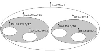
Figure 7-7: A hierarchical addressing and routing scheme showing routing regions and route summarization at region borders.
For a variety of reasons involving the impracticality of renumbering the IP internetwork, some IP internetworks have a combination of flat and hierarchical routing infrastructures. Before the development of CIDR, the Internet had a flat routing infrastructure. Post-CIDR, IP addresses are allocated using a hierarchical global addressing scheme. However,because of the difficulty of reallocating public network IDs to existing organizations, today's Internet remains a mixed flat and hierarchical routing infrastructure.
Static vs Dynamic
The ongoing maintenance of routing tables can be done either manually through static routing or automatically using dynamic routing.
Static Routing
Static routing relies on manually configured routes. It supports classless routing because each route must be added with a network mask, making the destination unambiguous. Static routing can work well for small internetworks but it does not scale well because of the manual administration involved. Static routing can also work well in branch office scenarios where, rather than using a routing protocol across the WAN link to the branch office, static routes are added to the branch office and hub office routers to make the locations on each other's network segments reachable.
Ideally, an IP router has explicit knowledge of each network ID in the internetwork, either through an explicit or aggregated route. Default routing is used when connecting a smaller set of network segments to a much larger set of network segments and the creation of explicit or aggregated routes is impractical or impossible. Static routes are often used to connect to the Internet. It is impractical to add the Internet's 80,000 routes to the routing table of the static router; therefore, add a single default route pointing to the downstream Internet service provider (ISP) router.
Static routing is not fault tolerant. A static router cannot sense that a neighboring router is no longer available (if the link to the neighboring router remains operational) or that a remote network segment is no longer reachable and make adjustments to its routing table.
The Windows Server 2003 Family as a Static IP Router
A computer running a member of the Windows Server 2003 family can act as a static IP router by installing multiple network adapters, creating a multihomed computer. A separate IP address and subnet mask is configured for each network adapter, defining routes for the directly attached networks. It is natural to want to configure a default gateway, but this creates a default route, and a default route on a static router is based on a design decision of your static routing environment.
If you use default routing, it is also natural for you to configure a default gateway for each network adapter. However, you must configure a default gateway for a single network adapter corresponding to the network adapter attached to the network segment of the router you want to use for your default route. If you configure a default gateway for more than one network adapter, a default route with an interfaced-based metric is added for each default gateway. This can lead to multiple default routes in the routing table with the same metric. In this situation, TCP/IP for the Windows Server 2003 family picks a default route based on the first network adapter binding. This can lead to undesired behavior if TCP/IP for the Windows Server 2003 family chooses a less than optimal default route.
Once the network adapters are configured, enable IP routing for computers running a member of the Windows Server 2003 family by configuring and enabling the Routing and Remote Access service. For computers running Microsoft Windows XP, set the following registry value to 1:
HKEY_LOCAL_MACHINESystemCurrentControlSetServicesTcpip
ParametersIpEnableRouter
After you enable IP routing, add the appropriate specific or aggregated routes of your internetwork using either the Routing and Remote Access administrative tool or the ROUTE ADD command at a command prompt.
Dynamic Routing
Dynamic routers rely on routing protocols—protocols used by routers to communicate routing information—to maintain IP routing tables. Routes for remote network IDs are learned through routing protocol traffic and added or removed from IP routing tables. When all of the IP internetwork routers have received all the information needed to create routes that reflect the internetwork's current topology, the internetwork has converged.
Dynamic routing in a multipath routing infrastructure can provide fault tolerance. When a route becomes unreachable, it is removed from the routing table and its unreachability is conveyed to neighboring routers. When a link or router goes down, routes are adjustedfor a new path to the network segments affected by the network fault. Routing protocols can be either class-based or classless depending on how the route is advertised.
The two most common IP routing protocols for private IP internetworks are RIP and OSPF, both of which are supported by the Windows Server 2003 family.
RIP
RIP is a distance vector routing protocol. Distance vector routing protocols propagate routing information in the form of a network ID and its "distance" or hop count. RIP has a maximum distance of 15 hops. Locations 16 or more hops away are considered unreachable. The original version of RIP, known as RIP version 1, described in RFC 1058, is a class-based routing protocol. The network ID is announced without its network mask. Therefore, the restrictions of class-based routing apply. A newer version of RIP, RIP version 2, described in RFC 1723, is a classless routing protocol. The RIP version 2 announcement includes a network ID and a subnet mask.
| More Info |
RFCs 1058 and 1723 describe RIP versions 1 and 2. These RFCs can be found in the Rfc folder on the companion CD-ROM. |
RIP is a simple routing protocol with a periodic route-advertising mechanism designed for use in small- to medium-sized IP internetworks. RIP does not scale well to large or very large IP internetworks.
RIP Operation
When a RIP router is initialized, it announces the appropriate routes in its routing table on all interfaces. The RIP router also sends a RIP General Request message on all interfaces. All neighboring routers—those on the same network segments as the router sending the request—send the contents of their routing tables in response; those responses build the initial routing table. Learned routes are given a three-minute lifetime (by default) before being removed by RIP from the IP routing table.
After initialization, the RIP router periodically announces (every 30 seconds, by default) the appropriate routes in its routing table for each interface. The exact set of routes being announced depends on whether the RIP router is implementing split horizon (where routes are not announced over the interfaces on which they were learned) or split horizon with poison reverse (where routes learned on interfaces are announced as unreachable).
Fault tolerance for RIP internetworks is based on the time-out of RIP-learned routes. If a change occurs in the internetwork topology, RIP routers can send a triggered update—a routing update, sent immediately—rather than waiting for a scheduled announcement.
OSPF
OSPF is a link state routing protocol. Link state routing protocols propagate routinginformation in the form of link state advertisements (LSAs) that contain the connected networks and their cost. The cost of each router interface is a unitless number that the network administrator assigns, and it can include delay, bandwidth, and monetary cost factors. The accumulated cost among network segments in an OSPF internetwork must be less than 65,535. OSPF is a classless routing protocol; OSPF LSAs contain the network ID and subnet mask for routes. OSPF is described in RFC 2328.
OSPF Operation
Each router has an LSA that describes its current state. The LSA of each OSPF router is efficiently propagated throughout the OSPF internetwork through logical relationships between neighboring routers called adjacencies. When the propagation of all current router LSAs is complete, the OSPF internetwork has converged.
Based on the collection of OSPF LSAs—known as the link state database—OSPF calculates the lowest cost path to each route, and those paths become OSPF routes in the IP routing table. To keep the size of the link state database down, OSPF allows the creation of areas. An OSPF area is a grouping of contiguous networks. In all OSPF networks, there is at least one area called the backbone area. OSPF areas allow the summarization or aggregation of routing information at the boundaries of an OSPF area. A router at the boundary of an OSPF area is known as an area border router (ABR).
Figure 7-8 shows an example of a multiple-area OSPF internetwork. Area 1 consists of a series of variable-length subnetted network segments from the address space 10.47.0.0/16. By default, the ABR for Area 1 propagates routing information in the form of LSAs for each separate network segment within Area 1. Using route summarization, the ABR is configured to propagate only the single route 10.47.0.0/16. All of the destinations within Area 1 are reachable outside of that area using this route. Areas and route summarization allow OSPF internetworks to scale to large organizational IP internetworks.
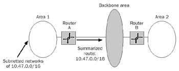
Figure 7-8: A multiple-area OSPF internetwork showing the route summarization of Area 1.
The Windows Server 2003 Family as a Dynamic Router
A computer running a member of the Windows Server 2003 family can act as a dynamic router supporting RIP and OSPF by installing multiple network adapters and enabling and configuring the Routing and Remote Access service. A separate IP address and subnet mask is configured for each network adapter, defining the directly attached network ID routes. In the case of dynamic routing, default routes are less typically used so a default gateway need not be configured for any network adapter.
After the Routing and Remote Access service is enabled, static IP routing is enabled. Using the Routing and Remote Access administrative tool, add the RIP for IP or OSPF routing protocols and then enable them on your installed network adapters by adding your network adapters to the appropriate routing protocol. The detailed configuration of RIP and OSPF options is beyond the scope of this book. For more information, see theWindows Server 2003 family online Help and the Microsoft Windows Server 2003 Resource Kit Internetworking Guide.
A computer running Microsoft Windows XP Professional can use the RIP protocol to listen to RIP traffic using the RIP Listener, a service installed as a separate networking component. A computer using the RIP Listener service is known as a silent RIP host. The RIP Listener service listens for all RIP version 1 broadcast traffic on the local network segment and maintains routes in the IP routing table.
Single vs Multiple Autonomous Systems
Very large IP internetworks such as the Internet are divided into regions called autonomous systems (ASs). An AS is a contiguous region of the internetwork under the same administrative control. Administrative control is typically defined by an organization such as an institution or corporation. Within an AS, one or more Interior Gateway Protocols (IGPs) are used. Examples of IGPs include RIP and OSPF. Between autonomous systems, Exterior Gateway Protocols (EGPs) are used. An example of an EGP is the Border Gateway Protocol version 4 (BGP-4). EGPs used between autonomous systems are independent of the IGPs used within the AS.
For most organizations, a single AS is often sufficient. The Internet, however, is a multiple-AS environment composed of a somewhat hierarchical organization of ASs using BGP-4 as the EGP. As seen with OSPF, each AS can be subdivided into areas or domains (if you are using multiple IGPs) to define a hierarchical structure within the AS. If you are an ISP, you might need to implement BGP-4 to communicate routing information to other Internet ASs. The Windows Server 2003 family does not provide support for BGP-4.
Routing Utilities
The Windows Server 2003 family provides the following command-line utilities for maintaining and testing routing functionality:
- RouteUsed to view the IP routing table, add temporary and persistent routes, change existing routes, and remove routes from the IP routing table.
- PingUsed to verify reachability by sending ICMP Echo messages to intended destinations. It also supports the use of IP strict and loose source route options.
- TracertSends ICMP Echo messages with incrementally higher values of the TTL field to discover the path between a node and a destination. In list form, Tracert displays the series of near-side router interfaces encountered by the ICMP Echo message as it traverses the internetwork toward the destination.
- PathpingUsed to discover the path between a host and a destination, and also to identify high-loss links or routers.
For more information about how Ping, Tracert, and Pathping work, see Chapter 8, "Internet Control Message Protocol (ICMP)."
Summary
IP routing is a combination of direct and indirect delivery processes that forward an IP datagram from the source node to the destination node. At each hop, a local IP routing table is consulted to determine how the datagram is delivered to the next hop or the final destination. The route determination process results in a next-hop interface and IP address. The routing infrastructure of an IP internetwork provides reachability between any source and destination node and can be class-based or classless, flat or hierarchical, and static or dynamic, and can consist of a single AS or multiple ASs. The Windows Server 2003 family supports static routing and dynamic routing using RIP version 1, RIP version 2, and OSPF.
Part I - The Network Interface Layer
- Local Area Network (LAN) Technologies
- Wide Area Network (WAN) Technologies
- Address Resolution Protocol (ARP)
- Point-to-Point Protocol (PPP)
Part II - Internet Layer Protocols
- Internet Protocol (IP) Basics
- Internet Protocol (IP) Addressing
- Internet Protocol (IP) Routing
- Internet Control Message Protocol (ICMP)
- Internet Group Management Protocol (IGMP)
- Internet Protocol Version 6 (IPv6)
Part III - Transport Layer Protocols
- User Datagram Protocol
- Transmission Control Protocol (TCP) Basics
- Transmission Control Protocol (TCP) Connections
- Transmission Control Protocol (TCP) Data Flow
- Transmission Control Protocol (TCP) Retransmission and Time-Out
Part IV - Application Layer Protocols and Services
- Dynamic Host Configuration Protocol (DHCP) Server Service
- Domain Name System (DNS)
- Windows Internet Name Service (WINS)
- File and Printer Sharing
- RADIUS and Internet Authentication Service
- Internet Information Services (IIS) and the Internet Protocols
- Internet Protocol Security (IPSec)
- Virtual Private Networks (VPNs)
EAN: N/A
Pages: 216
