Transmission Control Protocol (TCP) Basics
At the Transport Layer are two protocols that Application Layer protocols typically use for transporting data: TCP and User Datagram Protocol (UDP). TCP is the Transport Layer protocol that provides end-to-end reliable delivery service.
Introduction to TCP
TCP is a fully formed Transport Layer protocol that provides a reliable data-transfer service and a method to pass TCP-encapsulated data to an Application Layer protocol. TCP has the following characteristics:
- Connection-orientedBefore data can be transferred, two Application Layer processes must formally negotiate a TCP connection using the TCP connection establishment process. TCP connections are formally closed using the TCP connection termination process. For more information on TCP connection processes, see Chapter 13, "Transmission Control Protocol (TCP) Connections."
- Full duplexFor each TCP peer, the TCP connection consists of two logical pipes: an outgoing pipe and an incoming pipe. With the appropriate Network Interface Layer technology, data can be flowing out of the outgoing pipe and into the incoming pipe simultaneously. The TCP header contains both thesequence number of the outgoing data and an acknowledgment of the incoming data.
- ReliableData sent on a TCP connection is sequenced and a positive acknow-ledgment is expected from the receiver. If no acknowledgment is received,the segment is retransmitted. At the receiver, duplicate segments are dis-carded and segments arriving out of sequence are placed back in the proper sequence. A TCP checksum is always used to verify the bit-level integrity of the TCP segment.
- Byte streamTCP views the data sent over the incoming and outgoing logical pipes as a continuous stream of bytes. The sequence number and acknowledgment number in each TCP header are defined along byte boundaries. TCP is not aware of record or message boundaries within the byte stream. The Application Layer protocol must provide the proper parsing of the incoming byte stream.
- Sender- and receiver-side flow controlTo avoid sending too much data at one time and congesting the routers of the IP internetwork, TCP implements sender-side flow control that gradually scales the amount of data sent at one time. To avoid having the sender send data that the receiver cannot buffer, TCP implements receiver-side flow control that indicates the amount of space left in the receiver's buffer. For more information on how TCP implements sender- and receiver-side flow control, see Chapter 14, "Transmission Control Protocol (TCP) Data Flow."
- Segmentation of Application Layer dataTCP segments data obtained from the Application Layer process so that it will fit within an IP datagram sent on the Network Interface Layer link. TCP peers exchange the maximum-sized segment that each can receive and adjust the TCP maximum segment size using Path Maximum Transmission Unit (PMTU) discovery.
- One-to-one deliveryTCP connections are a logical point-to-point circuitbetween two Application Layer protocols. TCP does not provide a one-to-many delivery service.
TCP typically is used when the Application Layer protocol requires a reliable data transfer service and such a service is not provided by the Application Layer protocol itself.
The TCP Segment
TCP segments are sent as IP datagrams. A TCP segment, consisting of a TCP headerand a segment, is encapsulated with an IP header using IP Protocol number 6. The segment can be a maximum size of 65,495 bytes: 65,535 minus the minimum-size IP header (20 bytes) and the minimum-size TCP header (20 bytes). The resulting IP datagram is then encapsulated with the appropriate Network Interface Layer header and trailer. Figure 12-1 displays the resulting frame.
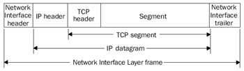
Figure 12-1: TCP segment encapsulation showing the IP header and Network Interface Layer header and trailer.
In the IP header of TCP segments, the Source IP Address field is set to the unicastaddress of the host interface that sent the TCP segment. The Destination IP Address field is set to the unicast address of a specific host.
The TCP Header
The TCP header is of variable length, consisting of the fields shown in Figure 12-2. When TCP options are not present, the TCP header is 20 bytes long.
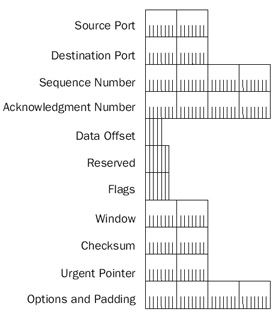
Figure 12-2: The structure of the TCP header.
The fields in the TCP header are defined as follows:
- Source PortA 2-byte field that indicates the source Application Layer protocol sending the TCP segment. The combination of the source IP address in the IP header and the source port in the TCP header provides a source socket—a unique, globally significant address from which the segment was sent.
- Destination PortA 2-byte field that indicates the destination Application Layer protocol. The combination of the destination IP address in the IP header and the destination port in the TCP header provides a destination socket—a unique, globally significant address to which the segment is sent.
- Sequence NumberA 4-byte field that indicates the outgoing byte-stream-based sequence number of the segment's first octet. The Sequence Numberfield is always set, even when there is no data in the segment. In this case, the Sequence Number field is set to the number of the outgoing byte stream's next octet. When establishing a TCP connection, TCP segments with a SYN (Synchronization) flag value of 1 set the Sequence Number field to the InitialSequence Number (ISN). This indicates that the first octet in the outgoingbyte stream sent on the connection is ISN + 1.
- Acknowledgment NumberA 4-byte field that indicates the sequence number of the next octet in the incoming byte stream that the receiver expects to receive. The acknowledgment number provides a positive acknowledgment of all octets in the incoming byte stream up to, but not including, the acknowledgment number. The acknowledgment number is significant in all TCP segments with the ACK (Acknowledgment) flag set.
- Data OffsetA 4-bit field that indicates where the TCP segment data begins. The Data Offset field is also the TCP header's size. Just as in the IP header's Header Length field, the Data Offset field is the number of 32-bit words (4-byte blocks) in the TCP header. For the smallest TCP header (no options), the Data Offset field is set to 5 (0x5), indicating that the segment data begins in the twentieth octet offset starting from the beginning of the TCP segment (the offset starts its count at 0). With a Data Offset field set to its maximum value of 15 (0xF), the largest TCP header, including TCP options, can be 60 bytes long.
- ReservedA 6-bit field that is reserved for future use. The sender sets these bits to 0.
- FlagsA 6-bit field that indicates six TCP flags. The six TCP flags, known as URG (Urgent), ACK, PSH (Push), RST (Reset), SYN, and FIN (Finish), are discussed in greater detail in the "TCP Flags" section of this chapter.
- WindowA 2-byte field that indicates the number of bytes of available space in the receive buffer of the sender of this segment. The receive buffer is used to store the incoming byte stream. By advertising the window size with each segment, a TCP receiver is telling the sender how much data can be sent and successfully buffered. The sender should not be sending more data than can fit in the receiver's buffer. If there is no more space in the receiver's buffer, a window size of 0 bytes is advertised. With a window size of 0, the sender cannot send any more data until the window size is a nonzero value. The advertisement of the window size is an implementation of receiver-side flow control.
- ChecksumA 2-byte field that provides a bit-level integrity check for the TCP segment (TCP header and segment). The Checksum field's value is calculated in the same way as the IP header checksum, over all the 16-bit words in a TCP pseudo header, the TCP header, the segment, and, if needed, a padding byte of 0x00. The padding byte is used only if the segment length is an odd number of octets. The value of the Checksum field is set to 0 during the checksumcalculation.
- Urgent PointerA 2-byte field that indicates the location of urgent data in the segment. The Urgent Pointer field and urgent data are discussed in the "TCPUrgent Data" section of this chapter.
- OptionsOne or more TCP options can be added to the TCP header but must be done in 4-byte increments so that the TCP header size can be indicated with the Data Offset field. TCP options are discussed in the section entitled "TCP Options," later in this chapter.
The following Network Monitor trace (Capture 12-01 in the Captures folder on the companion CD-ROM) shows the TCP header structure for File Transfer Protocol (FTP) traffic:
+ Frame: Base frame properties
+ ETHERNET: ETYPE = 0x0800 : Protocol = IP: DOD Internet Protocol
+ IP: ID = 0xDFC8; Proto = TCP; Len: 1500
 TCP: .A...., len: 1460, seq:1038577021-1038578481, ack:3930983524,
 win:17520, src: 20 dst: 1163
 TCP: Source Port = FTP [default data]
 TCP: Destination Port = 0x048B
 TCP: Sequence Number = 1038577021 (0x3DE76D7D)
 TCP: Acknowledgement Number = 3930983524 (0xEA4E0C64)
 TCP: Data Offset = 20 (0x14)
 TCP: Reserved = 0 (0x0000)
 TCP: Flags = 0x10 : .A....
 TCP:..0.....=No urgent data
 TCP:...1....=Acknowledgement field significant
 TCP:....0...=No Push function
 TCP:.....0..=No Reset
 TCP:......0.=No Synchronize
 TCP:.......0=No Fin
 TCP: Window = 17520 (0x4470)
 TCP: Checksum = 0xB489
 TCP: Urgent Pointer = 0 (0x0)
 TCP: Data: Number of data bytes remaining = 1460 (0x05B4)
+ FTP: Data Transfer To Client, Port = 1163, size 1460
TCP Ports
A TCP port defines a location for the delivery of TCP connection data. Included in each TCP segment is the source port that indicates the Application Layer process from which the segment was sent, and a destination port that indicates the Application Layerprocess to which the segment was sent. There are port numbers that are assigned bythe Internet Assigned Numbers Authority (IANA) to specific Application Layer protocols.
Table 12-1 shows assigned TCP port numbers used by the Microsoft Windows Server 2003 family and Windows XP components.
|
Port Number |
Application Layer Protocol |
|---|---|
|
19 |
Network News Transfer Protocol (NNTP) |
|
20 |
FTP Server (data channel) |
|
21 |
FTP Server (control channel) |
|
23 |
Telnet Server |
|
25 |
Simple Mail Transfer Protocol (SMTP) |
|
69 |
Trivial File Transfer Protocol (TFTP) |
|
80 |
Hypertext Transfer Protocol (HTTP; Web server) |
|
139 |
NetBIOS Session Service |
|
339 |
Lightweight Directory Access Protocol (LDAP) |
|
445 |
Direct-Hosted Server Message Block (SMB) |
See http://www.iana.org/assignments/port-numbers for the most current list of IANA-assigned TCP port numbers.
Typically, the server side of an Application Layer protocol listens on the well-known port number. The client side of an Application Layer protocol uses either the well-known port number or, more commonly, a dynamically allocated port number. These dynamically allocated port numbers are used for the duration of the process and are known also as ephemeral or short-lived ports. The following registry setting determines the range of port numbers that TCP/IP for the Windows Server 2003 family and Windows XP uses:
MaxUserPort
Location:
HKEY_LOCAL_MACHINESYSTEMCurrentControlSetServicesTcpipParameters
Data type: REG_DWORD
Valid range: 5000–65534
Default: 5000
Present by default: No
By default, the maximum port number is 5000. Dynamically allocated port numbers are within the range of 1024 through 5000 (0–1023 are reserved for well-known ports controlled by the IANA).
A TCP port number can be referenced, by name, by a Windows Sockets application using the GetServByName() function. The name is resolved to a TCP port number through the Services file stored in the %SystemRoot%System32DriversEtc folder.
A sending node determines the destination port (using either a specified value or the GetServByName() function) and the source port (using either a specified value, or by obtaining a dynamically allocated port through Windows Sockets). The sending node then passes the source IP address, destination IP address, source port, destination port, and the segment to be sent to TCP/IP. The TCP module calculates the Checksum field and indicates the TCP segment with the appropriate source IP address and destination IP address to the IP module.
When receiving a TCP segment at the destination, IP verifies the IP header. Then, based on the value of 6 in the Protocol field, IP passes the TCP segment, the source IP address, and the destination IP address to the TCP module. After verifying the TCP Checksum field, the TCP module verifies the destination port. If a process is listening on the port, the TCP segment is passed to the application. If no process is listening on the port, TCP sends a TCP Connection Reset segment to the sender. See Chapter 13, "Transmission Control Protocol (TCP) Connections," for a detailed discussion of the TCP Connection Reset segment.
Figure 12-3 shows the demultiplexing of received TCP connection data based on the TCP destination port.
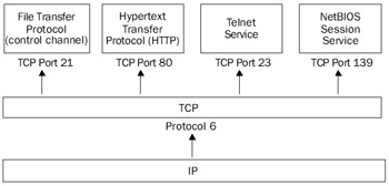
Figure 12-3: The demultiplexing of a TCP segment to the appropriate Application Layer protocol using the IP Protocol field and the TCP Destination Port field.
| Best Practice |
TCP ports are separate from UDP ports, even for the same port number. A TCP port represents one side of a TCP connection for an Application Layer protocol. A UDP port represents a UDP message queue for an Application Layer protocol. The Application Layer protocol using the TCP port is not necessarily the same Application Layer protocol using the UDP port. For example, the Extended Filename Server (EFS) protocol uses TCP port 520, and the Routing Information Protocol (RIP) uses UDP port 520. Clearly these are separate Appli cation Layer protocols. Therefore, it is good practice to never refer to a port by just its port number, which is ambiguous. Always refer to either a TCP port number or a UDP port number. |
TCP Flags
Figure 12-4 shows the six TCP flags in the Flags field of the TCP header.
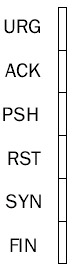
Figure 12-4: The six TCP flags in the Flags field of the TCP header.
The TCP flags are defined as follows:
- URG (Urgent Pointer field is significant)Indicates that the segment portion of the TCP segment contains urgent data and the Urgent Pointer field should be used to determine the location of the urgent data in the segment. Urgent data is discussed in more detail in the section "TCP Urgent Data," later in this chapter.
- ACK (Acknowledgment field is significant)Indicates that the Acknowledgment field contains the next octet expected on the connection. The ACK flag is always set, except for the first segment of a TCP connection establishment.
- PSH (the Push function)Indicates that the contents of the TCP receive buffer should be passed to the Application Layer protocol. The data in thereceive buffer must consist of a contiguous block of data from the left edge of the buffer. In other words, there cannot be any missing segments of the byte stream up to the segment containing the PSH flag; the data cannot be passed to the Application Layer protocol until missing segments arrive. Normally, the TCP receive buffer is flushed (the contents are passed to the Application Layer protocol) when the receive buffer fills with contiguous data or during normal TCP connection maintenance processes. The PSH flag overrides this default behavior and immediately flushes the TCP receive buffer. The PSH flag is used also for interactive Application Layer protocols such as Telnet, in which each keystroke in the virtual terminal session is sent with the PSH flag set. Another example of using the PSH flag is the setting of the PSH flag on the last segment of a file transferred with FTP. Data sent with the PSH flag does not have to be immediately acknowledged.
- RST (Reset the connection)Indicates that the connection is being aborted. For active connections, a TCP segment with the RST flag set is sent in response to a TCP segment received on the connection that is incorrect, causing theconnection to fail. The sending of an RST segment for an active connection forcibly terminates the connection, causing data stored in send and receive buffers or in transit to be lost. For TCP connections being established, an RST segment is sent in response to a connection establishment request to deny the connection attempt.
- SYN (Synchronize sequence number)Indicates that the segment contains an ISN. During the TCP connection establishment process, TCP sends a TCP segment with the SYN flag set. Each TCP peer acknowledges the receipt ofthe SYN flag by treating the SYN flag as if it were a single byte of data. The Acknowledgment Number field for the acknowledgment of the SYN segmentis set to ISN + 1.
- FIN (Finish sending data)Indicates that the TCP segment sender is finished sending data on the connection. When a TCP connection is gracefully terminated, each TCP peer sends a TCP segment with the FIN flag set. A TCP peer does not send a TCP segment with the FIN flag set until all outstanding datato the other TCP peer has been sent and acknowledged. Each peer acknowledges receipt of the FIN flag by treating it as if it were a single byte of data. When both TCP peers have sent segments with the FIN flag set and receivedacknowledgment of their receipt, the TCP connection is terminated.
The TCP Pseudo Header
The TCP pseudo header is used to associate the TCP segment with the IP header. The TCP pseudo header is added to the beginning of the TCP segment only during the checksum calculation and is not sent as part of the TCP segment. The use ofthe TCP pseudo header assures the receiver that a routing or fragmentation process did not improperly modify key fields in the IP header.
The TCP pseudo header consists of the Source IP Address field, the Destination IPAddress field, an Unused field set to 0x00, the Protocol field for TCP (set to 6), and the length of the TCP segment. When sending a TCP segment, TCP knows all of these values. When receiving a TCP segment, IP indicates all of these values to TCP. Figure 12-5 illustrates the TCP pseudo header.
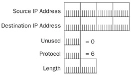
Figure 12-5: The structure of the TCP pseudo header.
The TCP checksum is calculated over the combination of the TCP pseudo header, the TCP segment, and, if needed, a 0x00 padding byte. The checksum calculation relies on summing 16-bit words. Therefore, the quantity over which the checksum is calculated must be an even number of octets. The padding byte is used only if the segment length is an odd number of octets. The padding byte is not included in the IP length and is not sent as part of the TCP segment. Figure 12-6 shows the resulting quantity for the calculation of the TCP Checksum field.
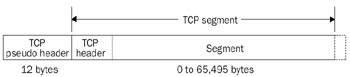
Figure 12-6: The resulting quantity used for the TCP checksum calculation.
| Note |
The TCP pseudo header and Checksum field are not providing data authentication and integrity as the IP Security (IPSec) Authentication header does. Key fields in the IP header can be modified as long as the TCP checksum is updated. This is how a Network Address Translator (NAT) works. A NAT is a router that translates public and private addresses during the forwarding process. Forexample, when translating a source IP address from a private address to a public address, the NAT also recalculates the TCP Checksum field. |
TCP Urgent Data
Normal data sent on a TCP connection is data corresponding to the incoming and outgoing byte stream data. In some data-transfer situations, there must be a method of sending control data to interrupt a process or inform the Application Layer protocol of asynchronous events. This control data is known as out of band data—data that is not part of the TCP byte stream but is needed to control the data flow. Out of band data for TCP connections can be implemented in the following ways:
- Use a separate TCP connection for the out of band data.The separate TCP connection sends control commands and status information without being combined on the data stream of the data connection. This is the method used by FTP. FTP uses a TCP connection on port 21 for control commands such as logins, gets (downloading files to the FTP client), and puts (uploading files to the FTP server), and a separate TCP connection on port 20 for the sending or receiving of file data.
- Use TCP urgent data.TCP urgent data is sent on the same TCP connec-tion as the data. TCP urgent data is indicated by setting the URG flag, and the urgent data is distinguished from the nonurgent data using the Urgent Pointer field. Urgent data within the TCP segment must be processed before the nonurgent data. Urgent data is used by the Telnet protocol to send control commands, even though the advertised receive window of the Telnet server is 0.
The interpretation of the Urgent Pointer value depends on the TCP implementation'sadherence to either RFC 793, the original TCP RFC, or RFC 1122, which defines requirements for Internet hosts.
- RFC 793 defines the value of the Urgent Pointer field as the positive offset from the beginning of the TCP segment to the first byte of nonurgent data.
- RFC 1122 defines the value of the Urgent Pointer field as the positive offset from the beginning of the TCP segment to the last byte of urgent data.
These two definitions of the Urgent Pointer field differ by one byte. Both hosts on a TCP connection must use the same interpretation, otherwise data corruption could occur. There is no interoperability of these two interpretations, nor is there a mechanism to negotiate the interpretation during the TCP connection establishment process.
The definition of the Urgent Pointer field in RFC 793 was made in error (the correctinterpretation is actually given later in the RFC during the discussion of event processing in Section 3.9). The correct use of the Urgent Pointer field is the RFC 1122 version, but numerous implementations of TCP use the RFC 793 definition.
| More Info |
The use of the TCP Urgent Pointer field is documented in RFCs 793 and 1122, which can be found in the Rfc folder on the companion CD-ROM. Figure 12-7 shows the placement of urgent data within the TCP segment and the RFC 793 and RFC 1122 interpretation of the Urgent Pointer field. |
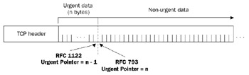
Figure 12-7: The location of TCP urgent data within a TCP segment.
The following registry setting for the Windows Server 2003 family and Windows XPallows you to configure the interpretation of the TCP Urgent Pointer field:
TcpUseRFC1122UrgentPointer
Key: HKEY_LOCAL_MACHINESYSTEMCurrentControlSetServicesTcpipParameters
Value type: REG_DWORD
Valid range: 0-1
Default: 0
Present by default: No
Set this value to 1 to use the RFC 1122 interpretation of the Urgent Pointer field, or set it to 0 to use the RFC 793 interpretation, which is the default.
TCP Options
Just like options in the IP header extend IP functionality, TCP options are used toextend TCP functionality. There are a variety of defined TCP options used for negotiating maximum segment sizes, scaling window sizes, performing selective acknowledgments, recording timestamps, and providing padding for 4-byte boundaries. A node is not required to support all TCP options; however, the support for processing TCPoptions is required. The presence of TCP options is indicated by a Data Offset field with a value greater than 5 (0x5). A TCP header with a size greater than 20 bytes contains TCP options.
A TCP option is either a single octet or multiple octets. For multiple-octet options, the TCP option is in type-length-value format, as shown in Figure 12-8, where the length is the length in octets of the entire option. A TCP option type is known as an option kind.
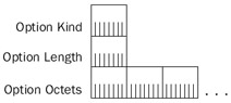
Figure 12-8: The Format for a Multiple-Octet TCP Option.
End Of Option List and No Operation
To implement 4-byte boundary support for TCP options, the following single-octet TCP options are defined:
- The End Of Option List TCP option is a single octet with the option kind set to 0 (0x00), which indicates that no other options follow. The End Of Option List option is not used to delimit TCP options. If the set of TCP options falls along a 4-byte boundary, this option is not needed.
- The No Operation TCP option is a single octet with the option kind set to 1 (0x01), which is used between TCP options for 4-byte alignment. The NoOperation option is not required, so TCP implementations must be able to correctly interpret TCP options that are not on 4-byte boundaries.
Maximum Segment Size Option
The TCP maximum segment size (MSS) is the largest segment that can be sent on the connection. To obtain the MSS value, take the IP Maximum Transmission Unit (MTU) and subtract the IP header size and the TCP header size. For a typical IP header (without options) and a typical TCP header (without options), the MSS is 40 octets less than the IP MTU, as shown in Figure 12-9.
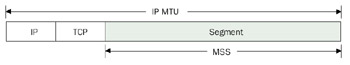
Figure 12-9: The TCP MSS defined in terms of the IP MTU and the TCP and IP header sizes.
The MSS TCP option is used to communicate a receiver's MSS. The MSS TCP option is included only in TCP segments with the SYN flag set during the TCP connection establishment process. Figure 12-10 shows the MSS TCP option structure.
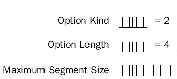
Figure 12-10: The structure of the TCP MSS option.
The fields in the TCP MSS option are defined as follows:
- Option KindSet to 2 (0x02) to indicate the MSS option kind.
- Option LengthSet to 4 (0x04) to indicate that the size of the entire TCPoption is 4 bytes.
- Maximum Segment SizeTwo bytes that indicate the maximum receive segment size of the sender of this TCP segment. For IP datagrams sent on an Ethernet network segment using Ethernet II encapsulation, the MSS is 1460 (an IP MTU of 1500 minus 40 bytes for minimum-sized IP and TCP headers).
The following Network Monitor trace (Capture 12-02 in the Captures folder on the companion CD-ROM) shows the MSS TCP option at the end of the TCP header for a SYN segment on an Ethernet network:
+ Frame: Base frame properties
+ ETHERNET: ETYPE = 0x0800 : Protocol = IP: DOD Internet Protocol
+ IP: ID = 0x28EA; Proto = TCP; Len: 48
 TCP: ....S., len: 0, seq:3928116524-3928116524, ack: 0, win:16384, src: 1162
 dst: 21 (FTP)
 TCP: Source Port = 0x048A
 TCP: Destination Port = FTP [control]
 TCP: Sequence Number = 3928116524 (0xEA224D2C)
 TCP: Acknowledgement Number = 0 (0x0)
 TCP: Data Offset = 28 (0x1C)
 TCP: Reserved = 0 (0x0000)
 + TCP: Flags = 0x02 : ....S.
 TCP: Window = 16384 (0x4000)
 TCP: Checksum = 0x854E
 TCP: Urgent Pointer = 0 (0x0)
 TCP: Options
 TCP: Maximum Segment Size Option
 TCP: Option Type = Maximum Segment Size
 TCP: Option Length = 4 (0x4)
 TCP: Maximum Segment Size = 1460 (0x5B4)
 TCP: Option Nop = 1 (0x1)
 TCP: Option Nop = 1 (0x1)
 + TCP: SACK Permitted Option
When two TCP peers exchange their MSS during the connection establishment process, both peers adjust their initial MSS to the minimum value reported by both. For example, when an Ethernet node sends an MSS of 1460 and a Fiber Distributed Data Interface (FDDI) node sends an MSS of 4312 (the FDDI IP MTU of 4352, minus 40 octets), both nodes agree to send maximum-sized TCP segments of 1460 octets. The initial MSS is adjusted on an ongoing basis through PMTU discovery. For example, two FDDI nodes on two separate FDDI rings—connected by routers over Ethernet network segments—exchange a TCP MSS of 4312. However, after TCP segments of 4312 octets are sent, PMTU discovery messages adjust the MSS for the connection to 1460. For more information on PMTU, see Chapter 8, "Internet Control Message Protocol (ICMP)."
The MSS TCP option does not prevent problems that could occur between two hosts on the same network segment that are separated by a Network Interface Layer technology with a lower IP MTU size. For example, consider Hosts A and B in Figure 12-11. They are on separate FDDI rings connected by a Fast Ethernet backbone.
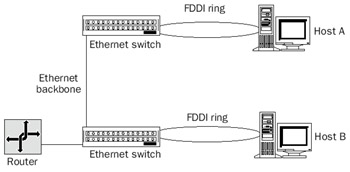
Figure 12-11: Hosts on two FDDI rings connected by an Ethernet backbone.
Both FDDI rings and the Ethernet backbone are on the same network segment as the router. Therefore, when Hosts A and B exchange MSS, both agree to send maximum-sized TCP segments with a size of 4312 octets. However, when they begin to send bulk data with maximum-sized segments, the translating bridges implemented by the Layer 2 switches have no facilities for translating 4352-octet FDDI payloads to 1500-octet Ethernet payloads. Therefore, the Layer 2 switch silently drops the maximum-sized TCP segments. Because the switch is not an IP router, no PMTU discovery messages are sent to the TCP peers to lower the MSS. The connection fails after one peer retransmits a maximum-sized TCP segment for the maximum allowable times.
If Host A were an FTP server and Host B were an FTP client, the user at Host B would be able to connect and log in to the FTP server. However, when the user issued a get or put instruction to send a file, the connection would hang and eventually terminate.
The only solution to this problem is to adjust the IP MTU on the FDDI nodes to the lowest value supported by all the Network Interface Layer technologies on the network segment. In this case, you would use the MTU registry setting described in Chapter 5, "Internet Protocol (IP) Basics," to lower the IP MTU of the two FDDI adapters to 1500.
TCP Window Scale Option
The TCP window size defined in RFC 793 is a 16-bit field for a maximum receive window size of 65,535 bytes. This means that a sender can have only 65,535 bytes of data in transit before having to wait for an acknowledgment. This is not an issue on typical local area network (LAN) and wide area network (WAN) links, but it is possible on newer LAN and WAN technologies operating at gigabit-per-second speeds with a sizable transit delay to have more than 65,535 bytes in transit. If TCP cannot fill the pipe and keep it filled, it is operating at lower efficiency.
The TCP Window Scale option described in RFC 1323 allows the receiver to advertise a larger window size than 65,535 bytes. The Window Scale option includes a window scaling factor that, when exponentially combined with the 16-bit window size in the TCP header, increases the receive window size to a maximum of 1,073,725,440 bytes (approximately 1 GB). The Window Size option is sent only in a SYN segment during the connection establishment process. Both TCP peers selectively indicate different window scaling factors used for their receive window sizes. The receiver of the TCP connection establishment request (the SYN segment) cannot send a Window Scale option unless the initial SYN segment contains it.
Figure 12-12 illustrates the TCP Window Scale option structure.

Figure 12-12: The structure of the TCP Window Scale option.
The fields in the TCP Window Scale option are defined as follows:
- Option KindSet to 3 (0x03) to indicate the Window Scale option kind.
- Option LengthSet to 3 (0x03) to indicate that the size of the entire TCPoption is three octets.
- Shift CountOne byte that indicates the scaling factor as the exponent of 2. For example, for a Shift Count of 5, the scaling factor is 25, or 32. The exponent is used rather than a whole number so that implementations can takeadvantage of binary shift programming techniques to quickly calculate theactual window size. For example, for a Shift Count of 5, the actual window size is the binary value of the Window field with five zeros added (the Window field is left-shifted by 5). The maximum value of the Shift Count is 14for a window scaling factor of 214, or 16,384.
The following Network Monitor trace (Capture 12-03 in the Captures folder on the companion CD-ROM) shows the Window Scale TCP option at the end of the TCP header for a SYN segment:
+ Frame: Base frame properties
+ ETHERNET: ETYPE = 0x0800 : Protocol = IP: DOD Internet Protocol
+ IP: ID = 0x2A1A; Proto = TCP; Len: 64
 TCP: ....S., len: 0, seq: 6727680-6727680, ack: 0, win:65528,
 src: 1049 dst: 21 (FTP)
 TCP: Source Port = 0x0419
 TCP: Destination Port = FTP [control]
 TCP: Sequence Number = 6727680 (0x66A800)
 TCP: Acknowledgement Number = 0 (0x0)
 TCP: Data Offset = 44 (0x2C)
 TCP: Reserved = 0 (0x0000)
 + TCP: Flags = 0x02 : ....S.
 TCP: Window = 65528 (0xFFF8)
 TCP: Checksum = 0xBDC5
 TCP: Urgent Pointer = 0 (0x0)
 TCP: Options
 + TCP: Maximum Segment Size Option
 TCP: Option Nop = 1 (0x1)
 TCP: Window Scale Option
 TCP: Option Type = Window Scale
 TCP: Option Length = 3 (0x3)
 TCP: Window Scale = 3 (0x3)
 TCP: Option Nop = 1 (0x1)
 TCP: Option Nop = 1 (0x1)
 + TCP: Timestamps Option
 TCP: Option Nop = 1 (0x1)
 TCP: Option Nop = 1 (0x1)
 + TCP: SACK Permitted Option
Notice the use of the No Operation TCP option (Nop) preceding the Window Scale option to align the Window Scale option on 4-byte boundaries.
When the Window Scale option is used, the window size advertised in each TCP segment for the connection is scaled by the factor indicated in the peer's SYN segment. Therefore, the TCP header's Window field is no longer a byte counter of the amount of space left in the receive buffer. Rather, the Window field is a block counter in which theblock size in bytes is the scaling factor. For example, for a TCP peer using a Shift Count of 3, the Window field in outgoing TCP segments is actually indicating the number of8-byte blocks remaining in the receive buffer.
The use of scaling windows is controlled through the following registry setting:
Tcp1323Opts
Key:HKEY_LOCAL_MACHINESYSTEMCurrentControlSetServicesTcpipParameters
Value type: REG_DWORD
Valid range: 0-3
Present by default: No
Set this value to 0 to disable both window scaling and timestamps. Set this value to 1 to enable only window scaling. Set this value to 2 to only enable timestamps. Set this value to 3 to enable both window scaling and timestamps. By default, the value is not set—TCP/IP does not initiate connections with window scaling or timestamp options but does provide them if requested.
| Note |
When tracing TCP connection data, make sure that you also look at the connection establishment process to determine whether window scaling is being used. Otherwise, you might misinterpret the Window field value during theconnection. |
Selective Acknowledgment Option
The acknowledgment scheme for TCP was originally designed as a positive cumulative acknowledgment scheme in which the receiver sends a segment with the ACK flag set and the Acknowledgment field set to the next octet the receiver expects to receive. This use of the Acknowledgment field provides an acknowledgment of all bytes up to, but not including, the sequence number in the Acknowledgment field. This scheme provides reliable byte-stream data transfer, but can result in lower TCP throughput in environments with high packet losses.
If a segment at the beginning of the current send window is not received and all other segments are, the data received cannot be acknowledged until the missing segmentarrives. The sender begins to retransmit the segments of the current send window until the acknowledgment for all the segments received has arrived. The sender needlesslyretransmits some segments, consequently wasting network bandwidth. This problem is exacerbated in environments such as satellite links, with high bandwidth and highdelay, when TCP has a large window size. The more segments in the send window, the more segments can be retransmitted unnecessarily when segments are lost.
RFC 2018 describes a method of selective acknowledgment using TCP options thatselectively acknowledges the noncontiguous data blocks that have been received. Whenthe sender receives a selective acknowledgment, it can retransmit just the missing blocks, preventing the sender from waiting for the retransmission time-out for the unacknowledged segments and retransmitting segments that have successfully arrived.
The selective acknowledgment scheme defines the following two different TCP options:
- The Selective Acknowledgment (SACK)-Permitted option to negotiate the use of selective acknowledgments during the connection establishment process
- The SACK option to indicate the noncontiguous data blocks that have beenreceived
More Info Selective acknowledgment is described in RFC 2018, which can be found in the Rfc folder on the companion CD-ROM.
The SACK-Permitted Option
The SACK-Permitted option is sent in segments with the SYN flag set and indicates that the TCP peer can receive and interpret the TCP SACK option when data is flowing on the connection. The SACK-Permitted option is 2 bytes consisting of an Option Kind set to 4 (0x04) and an Option Length set to 2 (0x02), as shown in Figure 12-13.

Figure 12-13: The structure of the TCP SACK-Permitted option.
The following Network Monitor trace (Capture 12-04 in the Captures folder on the companion CD-ROM) shows the TCP SACK-Permitted option at the end of the TCP header for a SYN segment:
+ Frame: Base frame properties
+ ETHERNET: ETYPE = 0x0800 : Protocol = IP: DOD Internet Protocol
+ IP: ID = 0x28EA; Proto = TCP; Len: 48
 TCP: ....S., len: 0, seq:3928116524-3928116524, ack: 0, win:16384, src: 1162
 dst: 21 (FTP)
 TCP: Source Port = 0x048A
 TCP: Destination Port = FTP [control]
 TCP: Sequence Number = 3928116524 (0xEA224D2C)
 TCP: Acknowledgement Number = 0 (0x0)
 TCP: Data Offset = 28 (0x1C)
 TCP: Reserved = 0 (0x0000)
 + TCP: Flags = 0x02 : ....S.
 TCP: Window = 16384 (0x4000)
 TCP: Checksum = 0x854E
 TCP: Urgent Pointer = 0 (0x0)
 TCP: Options
 + TCP: Maximum Segment Size Option
 TCP: Option Nop = 1 (0x1)
 TCP: Option Nop = 1 (0x1)
 TCP: SACK Permitted Option
 TCP: Option Type = Sack Permitted
 TCP: Option Length = 2 (0x2)
Notice the use of the two No Operation TCP option (Nop) fields preceding the SACK-Permitted option to align the SACK-Permitted option on 4-byte boundaries.
The SACK Option
The SACK option is sent as needed in segments of the open connection with the ACK flag set. As Figure 12-14 illustrates, the SACK option is a variable-size option, depending on how many contiguous blocks are being acknowledged.
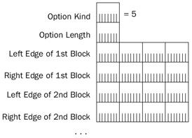
Figure 12-14: The structure of the TCP SACK option.
The fields in the TCP SACK option are defined as follows:
- Option KindSet to 5 (0x05) to indicate the SACK option kind.
- Option LengthSet to 10 (a single noncontiguous block), 18 (two noncontiguous blocks), 26 (three noncontiguous blocks), or 34 (four noncontiguous blocks) octets to indicate the size of the entire TCP option.
- Left Edge of Nth BlockA 4-byte field that indicates the sequence number of this block's first octet.
- Right Edge of Nth BlockA 4-byte field that indicates the next sequence number expected to be received immediately following this block.
The following Network Monitor trace (Capture 12-05 in the Captures folder on the companion CD-ROM) shows the TCP SACK option at the end of the TCP header for data being acknowledged:
+ Frame: Base frame properties
+ ETHERNET: ETYPE = 0x0800 : Protocol = IP: DOD Internet Protocol
+ IP: ID = 0xFA0D; Proto = TCP; Len: 64
 TCP: .A...., len: 0, seq: 925293-925293, ack: 55053434, win:32767,
 src: 1242 dst:139 (NBT Session)
 TCP: Source Port = 0x04DA
 TCP: Destination Port = NETBIOS Session Service
 TCP: Sequence Number = 925293 (0xE1E6D)
 TCP: Acknowledgement Number = 55053434 (0x3480C7A)
 TCP: Data Offset = 44 (0x2C)
 TCP: Reserved = 0 (0x0000)
 + TCP: Flags = 0x10 : .A....
 TCP: Window = 32767 (0x7FFF)
 TCP: Checksum = 0x436E
 TCP: Urgent Pointer = 0 (0x0)
 TCP: Options
 TCP: Option Nop = 1 (0x1)
 TCP: Option Nop = 1 (0x1)
 + TCP: Timestamps Option
 TCP: Option Nop = 1 (0x1)
 TCP: Option Nop = 1 (0x1)
 TCP: SACK Option
 TCP: Option Type = SACK
 TCP: Option Length = 10 (0xA)
 TCP: Left Edge of Block = 55054882 (0x3481222)
 TCP: Right Edge of Block = 55059226 (0x348231A)
In the trace, the sender of this segment is acknowledging the receipt of all contiguous octets in the byte stream up to, but not including, octet 55053434, and the receipt of the block of contiguous data from octets 55054882 through 55059225. There is a missing segment consisting of the octets 55053434 through 55054881. Notice the use of the Nop options to align the SACK option on 4-byte boundaries.
The use of selective acknowledgments and the SACK options are controlled through the following registry setting:
SackOpts
Key:HKEY_LOCAL_MACHINESYSTEMCurrentControlSetServicesTcpipParameters
Value type: REG_DWORD
Valid range: 0-1
Default: 1
Present by default: No
SackOpts either enables (when set to 1) or disables (when set to 0) the use of selective acknowledgments and the SACK options. SackOpts is enabled by default.
For more information on the use of selective acknowledgments to retransmit data, see Chapter 15, "Transmission Control Protocol (TCP) Retransmission and Time-Out."
TCP Timestamps Option
To set the retransmission time-out (RTO) on TCP segments sent, TCP monitors the round-trip time (RTT) on an ongoing basis. Normally, TCP calculates the RTT of a TCP segment and its acknowledgment once for every full send window of data. Although this works well in many environments, for high-bandwidth and high-delay environments such as satellite links with large window sizes, the sampling rate of one segment for each window size cannot monitor the RTT to determine the current RTO and prevent unnecessary retransmissions.
To calculate the RTT on any TCP segment, the segment is sent with the TCP Timestamps option described in RFC 1323. This option places a timestamp value based on a local clock on an outgoing TCP segment. The acknowledgment for the data in the TCP segment echoes back the timestamp, and the RTT can be calculated from the segment's echoed timestamp and the time (relative to the local clock) that the segment's acknowledgment arrived.
| More Info |
The TCP Timestamps option is described in RFC 1323, which can be found in the Rfc folder on the companion CD-ROM. |
Including the Timestamps option in the SYN segment during the connection establishment process indicates its use for the connection. Both sides of the TCP connection can selectively use timestamps. Once indicated during connection establishment, the timestamp can be included in TCP segments at the discretion of the sending TCP peer.
Figure 12-15 shows the TCP Timestamps option structure.
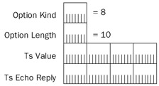
Figure 12-15: The structure of the TCP Timestamps option.
The fields in the TCP Timestamps option are defined as follows:
- Option KindSet to 8 (0x08) to indicate the Timestamps option kind.
- Option LengthSet to 10 (0x0A) to indicate that the size of the entire TCP option is 10 octets.
- TS ValueA 4-byte field that indicates the timestamp value of this TCP segment. The TS Value is calculated from an internal clock that is based on real time. The TS Value increases over time and wraps around when needed.
- TS Echo ReplyA 4-byte field set on a TCP segment that acknowledges data received (with the ACK flag set) that is set to the same value as the TS Value for the received segment being acknowledged. In other words, the TS Echo Reply is an echo of the TS Value of the acknowledged segment.
Figure 12-16 illustrates an example of the values of the TS Value and TS Echo Reply for an exchange of data between two hosts.
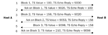
Figure 12-16: An example of the use of the TCP Timestamps option.
Host A's internal clock starts its TS Value at 100. Host B's internal clock starts its TS Value at 9000. Segments 1 through 4 are for two data blocks sent by Host A. Segments 5 and 6 are for a data block sent by Host B. Notice how the TS Echo Reply value for theacknowledgments is set to the TS Value of the segments they are acknowledging. To prevent gaps in the sending of data from increasing the RTT, the TS Echo Reply is used for RTT measurement only if the segment is an acknowledgment of new data sent.
The following Network Monitor trace (Capture 12-06 in the Captures folder on the companion CD-ROM) shows two frames—a frame of data containing the TCP Timestamps option and its corresponding acknowledgment:
+ Frame: Base frame properties
+ ETHERNET: ETYPE = 0x0800 : Protocol = IP: DOD Internet Protocol
+ IP: ID = 0x1A15; Proto = TCP; Len: 1500
 TCP: .A...., len: 1448, seq: 55050538-55051986, ack: 925293, win:16564,
 src: 139 (NBT Session) dst: 1242
 TCP: Source Port = NETBIOS Session Service
 TCP: Destination Port = 0x04DA
 TCP: Sequence Number = 55050538 (0x348012A)
 TCP: Acknowledgement Number = 925293 (0xE1E6D)
 TCP: Data Offset = 32 (0x20)
 TCP: Reserved = 0 (0x0000)
 + TCP: Flags = 0x10 : .A....
 TCP: Window = 16564 (0x40B4)
 TCP: Checksum = 0xBD81
 TCP: Urgent Pointer = 0 (0x0)
 TCP: Options
 TCP: Option Nop = 1 (0x1)
 TCP: Option Nop = 1 (0x1)
 TCP: Timestamps Option
 TCP: Option Type = Timestamps
 TCP: Option Length = 10 (0xA)
 TCP: Timestamp = 4677 (0x1245)
 TCP: Reply Timestamp = 7114 (0x1BCA)
 TCP: Data: Number of data bytes remaining = 1448 (0x05A8)
+ NBT: SS: Session Message Cont., 1448 Bytes
________________________________________________________________________________
+ Frame: Base frame properties
+ ETHERNET: ETYPE = 0x0800 : Protocol = IP: DOD Internet Protocol
+ IP: ID = 0xF60D; Proto = TCP; Len: 52
 TCP: .A...., len: 0, seq: 925293-925293, ack: 55051986, win:32722,
 src: 1242 dst:139 (NBT Session)
 TCP: Source Port = 0x04DA
 TCP: Destination Port = NETBIOS Session Service
 TCP: Sequence Number = 925293 (0xE1E6D)
 TCP: Acknowledgement Number = 55051986 (0x34806D2)
 TCP: Data Offset = 32 (0x20)
 TCP: Reserved = 0 (0x0000)
 + TCP: Flags = 0x10 : .A....
 TCP: Window = 32722 (0x7FD2)
 TCP: Checksum = 0x84D1
 TCP: Urgent Pointer = 0 (0x0)
 TCP: Options
 TCP: Option Nop = 1 (0x1)
 TCP: Option Nop = 1 (0x1)
 TCP: Timestamps Option
 TCP: Option Type = Timestamps
 TCP: Option Length = 10 (0xA)
 TCP: Timestamp = 7126 (0x1BD6)
 TCP: Reply Timestamp = 4677 (0x1245)
Notice that in the second frame the Reply Timestamp (TS Echo Reply) field is set to 4677, echoing the Timestamp (TS Value) field of the first frame.
The use of TCP timestamps for the Windows .NET Server 2003 family and Windows XP is controlled through the Tcp1323Opts registry setting discussed in the section "TCPWindow Scale Option," earlier in this chapter.
For more information on RTT, RTO, and retransmission behavior, see Chapter 15, "Transmission Control Protocol (TCP) Retransmission and Time-Out."
Summary
TCP provides connection-oriented and reliable data transfer for applications that require end-to-end guaranteed delivery service. Application Layer protocols use TCP for one-to-one traffic. The TCP header provides sequencing, acknowledgment, a checksum, and the identification of source and destination port numbers to multiplex TCP segment data to the proper Application Layer protocol. TCP options are used to indicate maximum segment sizes, indicate window scaling, indicate and provide selective acknowledgments, and provide timestamps for better RTT determination..
Part I - The Network Interface Layer
- Local Area Network (LAN) Technologies
- Wide Area Network (WAN) Technologies
- Address Resolution Protocol (ARP)
- Point-to-Point Protocol (PPP)
Part II - Internet Layer Protocols
- Internet Protocol (IP) Basics
- Internet Protocol (IP) Addressing
- Internet Protocol (IP) Routing
- Internet Control Message Protocol (ICMP)
- Internet Group Management Protocol (IGMP)
- Internet Protocol Version 6 (IPv6)
Part III - Transport Layer Protocols
- User Datagram Protocol
- Transmission Control Protocol (TCP) Basics
- Transmission Control Protocol (TCP) Connections
- Transmission Control Protocol (TCP) Data Flow
- Transmission Control Protocol (TCP) Retransmission and Time-Out
Part IV - Application Layer Protocols and Services
- Dynamic Host Configuration Protocol (DHCP) Server Service
- Domain Name System (DNS)
- Windows Internet Name Service (WINS)
- File and Printer Sharing
- RADIUS and Internet Authentication Service
- Internet Information Services (IIS) and the Internet Protocols
- Internet Protocol Security (IPSec)
- Virtual Private Networks (VPNs)
EAN: N/A
Pages: 216
