Internet Group Management Protocol (IGMP)
Overview
Historically, data transfer services used one-to-one delivery, using unicast addressing and routing across an IP internetwork. The utility of one-to-many delivery across an IP internetwork has recently become an interesting and cost-effective way to deliver audio, video, and other types of content to multiple destinations. One-to-many delivery service requires hosts to inform local routers of their interest in receiving the traffic so that routers can forward the traffic to the network segments of the listening hosts.
Introduction to IP Multicast and IGMP
IP multicast provides an efficient one-to-many delivery service. To achieve one-to-many delivery using IP unicast traffic, each datagram needs to be sent multiple times. To achieve one-to-many delivery using IP broadcast traffic, a single datagram is sent, but all nodes process it, even those that are not interested. Broadcast delivery service is unsuitable for internetworks, as routers are designed to prevent the spread of broadcast traffic. With IP multicast, a single datagram is sent and forwarded across routers only to the network segments containing nodes that are interested in receiving it.
Historically, IP multicast traffic has been little utilized. However, recent developments in audio and video teleconferencing, distance learning, and data transfer to a large number of hosts have made IP multicast traffic more important.
| More Info |
RFCs 1112 and 2236 describe IP multicast and the Internet Group Management Protocol (IGMP). These RFCs can be found in the Rfc folder on the companion CD-ROM. |
IP Multicasting Overview
The following are the essential details of IP multicast operation:
- All multicast traffic is sent to a class D address in the range 224.0.0.0 through 239.255.255.255 (224.0.0.0/4). All traffic in the range 224.0.0.0 through 224.0.0.255 (224.0.0.0/24) is for the local subnet and is not forwarded by routers. Multicast-enabled routers forward multicast traffic in the range 224.0.1.0 through 239.255.255.255 with an appropriate Time to Live (TTL).
- A specific multicast address is called a group address.
- The set of hosts that listen for multicast traffic at a specific group address is called a multicast group or host group. Multicast group members can receive traffic to their unicast address and the group address. Multicast groups can be permanent or transient. A permanent group is assigned a well-known group address. An example of a permanent group is the all-hosts multicast group, listening for traffic on the well-known multicast address of 224.0.0.1. The membership of a permanent group is transient; only the group address is permanent.
- There are no limits on a multicast group's size.
- A host can send multicast traffic to the group address without belonging to the multicast group.
- There are no limits to how many multicast groups to which a host can belong.
- There are no limits on when members of a multicast group can join and leave a multicast group.
- There are no limits on the location of multicast group members.
IP multicast must be supported by the hosts and the routers of an IP internetwork.
Host Support
To support IP multicast, hosts must be able to send and receive IP multicast traffic.RFC 1112 defines three levels of IP multicast support for hosts as follows:
- Level 0No support for sending or receiving IP multicast traffic
- Level 1Support for sending IP multicast traffic
- Level 2Support for sending and receiving IP multicast traffic
The IP multicast support level is controlled through the following registry setting:
IGMPLevel
Location:
HKEY_LOCAL_MACHINESYSTEMCurrentControlSetServicesTcpipParameters
Value Type: REG_DWORD
Valid Range: 0-2
Default: 2
Present by Default: No
By default, TCP/IP for the Windows Server 2003 family supports Level 2IP multicasting.
Sending IP Multicast Traffic
A host sending an IP multicast packet must first determine the IP multicast address. The IP multicast address is determined by either the application or protocol (a well-known or reserved IP multicast address), or obtained from a server allocating unique IP multicast addresses. Multicast Address Dynamic Client Allocation Protocol (MADCAP) is an extension to the Dynamic Host Configuration Protocol (DHCP) standard that is used to obtain a unique IP multicast address. Multicast scopes configured on the DHCP server define rangesof IP multicast addresses. Similar to allocating unicast IP addresses, unique IP multicast addresses are allocated to a single DHCP client. If multiple hosts use the same IP multicast address for different applications, the wrong traffic could be forwarded to host group members. For more information on multicast support by the DHCP service in theWindows Server 2003 family, see Chapter 16, "Dynamic Host Configuration Protocol (DHCP) Server Service."
After determining the destination IP multicast address, the sending host must construct the IP datagram with its own IP address as the source IP address, the intended IP multicast address as the destination IP address, and an appropriate TTL value. For local subnet IP multicast traffic destined for addresses in the range 224.0.0.0 through 224.0.0.255 (224.0.0.0/24), the TTL is set to 1. Routers do not forward IP multicast traffic in this range even if the TTL is greater than 1. For nonlocal subnet traffic, the TTL should be set to a value that is high enough to reach all host group members. Table 9-1 lists the recommended values of the TTL for IP multicast traffic and their scope.
|
TTL Value |
Description |
|---|---|
|
0 |
Restricted to the same host |
|
1 |
Restricted to the same subnet |
|
15 |
Restricted to the same site |
|
63 |
Restricted to the same region |
|
127 |
Worldwide |
|
191 |
Worldwide; limited bandwidth |
|
255 |
Unrestricted |
Once the sending host constructs the IP multicast datagram, the IP packet is passed through the IP forwarding process. The multicast entry in the IP routing table (the route(s) with the destination of 224.0.0.0 and the network mask of 240.0.0.0) informs IP that the datagram must be forwarded to the destination IP address, using the local network interface. The IP datagram, the forwarding IP address, and the interface are submitted to theAddress Resolution Protocol (ARP).
The ARP module checks the forwarding IP address. Because the forwarding IP address is in the range 224.0.0.0 through 239.255.255.255 (224.0.0.0/4), ARP bypasses the process of checking the ARP cache and sending a broadcast ARP Request frame. For Ethernet and Fiber Distributed Data Interface (FDDI) hosts, the destination IP address is mapped to the destination media access control (MAC) address using the process described in Chapter 6, "Internet Protocol (IP) Addressing." For Token Ring hosts, all IP multicast traffic isaddressed to the Token Ring functional address of 0xC0-00-00-04-00-00 unless otherwise specified with the TrFunctionalMcastAddress registry setting.
Receiving IP Multicast Traffic
To receive IP multicast traffic, a host informs the IP layer to process traffic for a specific group address. To facilitate the request, the IP module does the following:
- Informs the Network Interface Layer technology to add the MAC-level multicast address that corresponds to the group address to the list of interesting destination MAC addresses. In the Windows Server 2003 family, the IP module within the TCP/IP protocol uses the NDISRequest( ) function.
- If the group address is not in the range 224.0.0.1 through 224.0.0.255 (224.0.0.0/24), an IGMP Host Membership Report message is sent to inform local routers to forward the host group traffic to the network segment of the listening host.
If there are multiple applications on the host using the same group address, IP tracksapplication group membership and passes a copy of the received IP multicast datagram to each listening application. For a multihomed host, IP tracks group membership for each network segment.
Router Support
To support IP multicast forwarding and routing, a router must be able to do the following:
- Listen for IGMP Host Membership Report messages sent from hosts on local network segments.
- Track and maintain group membership for hosts on local network segments. Routers maintain host group membership through the receipt of IGMP Host Membership Report messages and the sending of IGMP Host Membership Query messages.
- In a multicast-enabled intranet with more than two routers, a router must be able to communicate host group membership information to neighboring routers. This is done using a multicast routing protocol such as Distance Vector Multicast Routing Protocol (DVMRP), Multicast Extensions to Open Shortest Path First (MOSPF), or Protocol Independent Multicast (PIM).
- Listen for all IP multicast traffic on all attached network segments. To do this, the router must put the network interface into either promiscuous listening mode or multicast promiscuous listening mode. In promiscuous mode, all incoming frames are considered interesting and passed to upper layers for processing. Promiscuous mode is a processor and interrupt-intensive listening mode typically used only for protocol analysis or network sniffing.
Multicast promiscuous mode is a special listening mode in which all packets with the Individual/Group (I/G) bit set in the destination MAC address are considered interesting. The I/G bit is also known as the multicast bit. For Ethernet frames, the multicast bit is the last bit of the first byte in the destination MAC address. In multicast promiscuous mode, all frames with the multicast bit set and a valid Frame Check Sequence (FCS) field are passed up to the operating system forprocessing. See Chapter 1, "Local Area Network (LAN) Technologies," for more information on the multicast bit. In multicast promiscuous mode, an IP multicast router receives a copy of every IP multicast packet for processing or forwarding. Not all network adapters support multicast promiscuous mode. A network adapter that supports promiscuous mode might not support multicast promiscuous mode.
- Forward IP multicast traffic with a valid TTL on appropriate network segments where there are host group members or where there are downstream routers that have host group members. The IP multicast forwarding capability is provided by the TCP/IP protocol. Similar to unicast forwarding, when IP multicast forwarding is enabled, the TTL of the packet being forwarded is decremented, and is then forwarded over the appropriate interfaces based on the entries in a local multicast forwarding table. IP silently discards multicast traffic with a TTL of 0.
IP multicast traffic is forwarded to network segments that have either a listening host or a router that has informed the router forwarding the IP multicast traffic that there are host group members downstream. The entries in the IP multicast forwarding table do not indicate which hosts are listening or how many group members there are on a network segment—only that at least one host member is present on the network segment (or a downstream network segment).
The Multicast Enabled IP Internetwork
Figure 9-1 shows a multicast-enabled intranet. To support the forwarding of IP multicast traffic from any host to any group member, hosts and routers must support the following criteria:
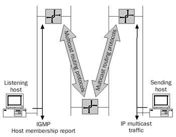
Figure 9-1: A multicast-enabled intranet showing multicast-enabled hosts and routers.
- Any host receiving IP multicast traffic joins the multicast group by sending IGMP Host Membership Report messages on the local network segment.
- Any host sending IP multicast traffic forms the IP multicast frame and sends it on the local network segment.
- IP multicast routers forward the IP multicast traffic from the originating network segment to all segments where there are group members. IGMP Host Membership Report messages inform the routers about group members onlocally attached network segments. For downstream host members, IP multicast routers communicate downstream host member information using multicast routing protocols. In both cases, IGMP and multicast routing protocols update the router's local TCP/IP multicast forwarding tables.
The Internet's Multicast-Enabled Backbone
The portion of the Internet that is IP-multicast-enabled is known as the multicast backbone (MBONE). The MBONE was originally created to multicast the audio for Internet Engineering Task Force (IETF) meetings for members who could not attend. Today, the MBONE is used for the audio and video of IETF meetings, launches of the National Aeronautic and Space Administration (NASA) space shuttle, and teleconferences of all kinds. The MBONE is also the testbed for the development of IP multicast technology such as applications, tools, and routing protocols.
The MBONE is a logical IP multicast topology overlaid on the Internet's physical unicast topology. Not all Internet portions and Internet service providers (ISPs) support the forwarding of IP multicast traffic. To connect two portions of the Internet that supportIP multicast traffic, IP multicast traffic is tunneled or wrapped with another IP headeraddressed from one router to another router. The typical tunneling is called IP-in-IPtunneling, described in RFC 1853. The MBONE is a series of multicast-enabled islands connected together with IP-in-IP tunnels.
| More Info |
IP-in-IP tunneling is described in RFC 1853, which can be found in the Rfc folder on the companion CD-ROM. |
IGMP Message Structure
IGMP is the protocol used to maintain local subnet host group membership, and it is required for hosts that support Level 2 IP multicasting. IGMP messages are sent as IP datagrams with the IP Protocol field set to 2. Therefore, an IGMP message is encapsulated with an IP header. The resulting IP datagram is then encapsulated with the appropriate Network Interface Layer header and trailer. Figure 9-2 shows the resulting frame.
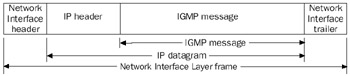
Figure 9-2: IGMP message encapsulation showing the IP header and Network Interface Layer header and trailer.
In the IP header of IGMP messages, the Source IP Address field is set to the router or host interface that sent the IGMP message; the Destination IP Address field depends on the type of IGMP message.
IGMP Version 1 (IGMPv1)
IGMPv1 defines two types of IGMP messages: the Host Membership Report and the Host Membership Query.
| More Info |
IGMPv1 is described in Appendix I of RFC 1112, which can be found in the Rfc folder on the companion CD-ROM. |
Host Membership Report
A host sends a Host Membership Report message to inform local routers that the host wants to receive IP multicast traffic at a specified group address. A host also sends a Host Membership Report in response to a Host Membership Query message sent by a router. Host Membership Report messages are sent, with a TTL of 1, to the destination IPaddress of the multicast group.
Host Membership Query
A router sends a Host Membership Query message to poll a network segment and verify that there are hosts still listening for IP multicast traffic. Host Membership Query messages are sent, with a TTL of 1, to the destination IP address of the all-hosts IP multicast address (224.0.0.1). An IGMPv1 Host Membership Query is a general query, attempting to identify all multicast groups being listened to by hosts on a network segment.
Hosts that receive the Host Membership Query message send a Host Membership Report message for all the host groups for which they are members. To prevent an avalanche of response traffic, host group members choose a random report delay time for each host group and wait to hear from other host group members on the network segment. If another host group member sends a Host Membership Report message, the waiting host does not send a reply.
This behavior is consistent with the information kept by multicast routers. A multicast router does not track which hosts on a network segment are members of a host group, only that there is at least one host group member.
If no hosts respond with a Host Membership Report to a group address that the multicast router is tracking for the network segment, the multicast router can remove that entry from the multicast forwarding table and inform other multicast routers through multicast routing protocols. Multicast traffic to the removed group address is no longer forwarded to the network segment.
IGMPv1 Message Structure
Figure 9-3 shows the structure of the IGMPv1 message.
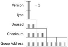
Figure 9-3: The structure of the IGMPv1 message.
The fields in the IGMPv1 header are defined as follows:
- VersionA 4-bit field set to 1 to indicate IGMPv1.
- TypeA 4-bit field that indicates the type of IGMP message. Set to 1 for a Host Membership Query. Set to 2 for a Host Membership Report.
- UnusedA 1-byte field zeroed by the sender and ignored by the receiver.
- ChecksumA 2-byte field that stores the checksum on the 8-byte IGMPmessage.
- Group AddressA 4-byte field that for a Host Membership Report stores the multicast group address being joined by the listening host. In a Host Membership Query, the Group Address field is 0.0.0.0.
Table 9-2 summarizes the addresses used in IGMPv1 Host Membership Report and Host Membership Query messages.
|
Host Membership Report |
Host Membership Query |
|
|---|---|---|
|
Source IP Address (IP header) |
Host IP Address |
Router IP Address |
|
Destination IP Address (IP header) |
Group IP Address |
224.0.0.1 |
|
Group Address |
Group IP Address |
0.0.0.0 |
Network Monitor Examples
The following Network Monitor trace (Capture 09-01 in the Captures folder on the companion CD-ROM) is an IGMPv1 Host Membership Report message for a host joining the host group 224.0.1.41:
+ FRAME: Base frame properties
 ETHERNET: ETYPE = 0x0800 : Protocol = IP: DOD Internet Protocol
 ETHERNET: Destination address : 01005E000129
 ETHERNET: .......1 = Group address
 ETHERNET: ......0. = Universally administered address
 + ETHERNET: Source address : 00C04FD7BAEC
 ETHERNET: Frame Length : 60 (0x003C)
 ETHERNET: Ethernet Type : 0x0800 (IP: DOD Internet Protocol)
 ETHERNET: Ethernet Data: Number of data bytes remaining = 46 (0x002E)
 IP: ID = 0xB201; Proto = IGMP; Len: 28
 IP: Version = 4 (0x4)
 IP: Header Length = 20 (0x14)
 IP: Precedence = Routine
 IP: Type of Service = Normal Service
 IP: Total Length = 28 (0x1C)
 IP: Identification = 45569 (0xB201)
 + IP: Flags Summary = 0 (0x0)
 IP: Fragment Offset = 0 (0x0) bytes
 IP: Time to Live = 1 (0x1)
 IP: Protocol = IGMP - Internet Group Management
 IP: Checksum = 0x118E
 IP: Source Address = 10.0.11.40
 IP: Destination Address = 224.0.1.41
 IP: Data: Number of data bytes remaining = 8 (0x0008)
 IP: Padding: Number of data bytes remaining = 18 (0x0012)
 IGMP: Version 1 Membership Report
 IGMP: Type = Version 1 Membership Report
 IGMP: Unused = 0 (0x0)
 IGMP: Checksum = 0x0CD6
 IGMP: Group Address = 224.0.1.41
Note that the group address of 224.0.1.41 is being mapped to the Ethernet destination address of 01-00-5E-00-01-29 (41 in hexadecimal is 0x29). Also note that IGMP messages must be padded with 18 padding bytes on Ethernet networks to adhere to the Ethernet minimum payload size of 46 bytes (padding bytes not shown).
The following Network Monitor trace (Capture 09-02 in the Captures folder on the companion CD-ROM) is an IGMPv1 Host Membership Query message:
+ FRAME: Base frame properties
 ETHERNET: ETYPE = 0x0800 : Protocol = IP: DOD Internet Protocol
 ETHERNET: Destination address : 01005E000001
 ETHERNET: .......1 = Group address
 ETHERNET: ......0. = Universally administered address
 + ETHERNET: Source address : 00E034C0A060
 ETHERNET: Frame Length : 60 (0x003C)
 ETHERNET: Ethernet Type : 0x0800 (IP: DOD Internet Protocol)
 ETHERNET: Ethernet Data: Number of data bytes remaining = 46 (0x002E)
 IP: ID = 0x0; Proto = IGMP; Len: 28
 IP: Version = 4 (0x4)
 IP: Header Length = 20 (0x14)
 IP: Precedence = Internetwork Control
 IP: Type of Service = Normal Service
 IP: Total Length = 28 (0x1C)
 IP: Identification = 0 (0x0)
 + IP: Flags Summary = 0 (0x0)
 IP: Fragment Offset = 0 (0x0) bytes
 IP: Time to Live = 1 (0x1)
 IP: Protocol = IGMP - Internet Group Management
 IP: Checksum = 0xC71E
 IP: Source Address = 10.0.8.1
 IP: Destination Address = 224.0.0.1
 IP: Data: Number of data bytes remaining = 8 (0x0008)
 IP: Padding: Number of data bytes remaining = 18 (0x0012)
 IGMP: Membership Query
 IGMP: Type = Membership Query
 IGMP: Max Resp Time = 100 (0x64)
 IGMP: Checksum = 0xEE9B
 IGMP: Group Address = 0.0.0.0
Notice that for both traces, the IP header's TTL field is set to 1.
IGMP Version 2 (IGMPv2)
IGMPv2 provides additional capabilities to help multicast routers converge a multicast group to the set of hosts listening for traffic. IGMPv2 is backward compatible with IGMPv1.
The additional capabilities of IGMPv2 are as follows:
- The Leave Group message
- The Group-Specific Query message
- The election of a multicast querier
- The IGMPv2 Host Membership Report message
More Info IGMPv2 is described in RFC 2236, which can be found in the Rfc folder on the companion CD-ROM.
The Leave Group Message
With IGMPv1, if a host leaves a specific multicast group and it is the last member of the multicast group for that subnet, the local router is not explicitly informed. The router maintains the entry in its multicast forwarding table and continues to forward multicast traffic to the host's subnet. Only after the router sends a Host Membership Query message and receives no response for the multicast group does the router recognize that there are no more hosts on that network segment for that group address. The router then updates its multicast forwarding table, discontinues forwarding IP multicast traffic to the network segment, and informs neighboring routers of the new state. This can lead to long leave latency times. During the leave latency time, multicast traffic is forwarded to network segments that do not contain group members.
During the periodic polling process, when an IGMPv2 host responds to a membership query, it assumes that it is potentially the last member in the group for that subnet because no other hosts responded before it. If that host leaves the group, it sends an IGMP Leave Group message to the all-routers IP multicast address. To ensure that the host leaving is truly the last host in the group for the subnet, the multicast router sends a series of group-specific membership queries. If the multicast router receives a response from another host for that group, the router maintains the group membership state for that group on that subnet. If the multicast router does not receive any responses, it can prevent the forwarding of traffic to that group to the subnet. If there are host members on downstream subnets available across subnet routers, multicast traffic for the group is still forwarded to the subnet.
The Group-Specific Query Message
In the case of IGMPv2, two different types of Host Membership Query messages are defined: the General Query and the Group-Specific Query. The General Query is the same as the IGMPv1 Host Membership Query. The Group-Specific Query is designed to check for host membership in a specific group. In the Group-Specific Query, the IP header's destination IP address and the IGMP header's group address are set to the group address being queried.
The Multicast Querier
IGMPv2 supports the election of a multicast querier, a single router per network segment that sends Host Membership Query messages. With IGMPv1, the designation of a single multicast router to perform queries is a function of the multicast routing protocol. Because all IGMP traffic is sent to multicast addresses, every multicast router on a network segment receives all IGMP messages. Therefore, only a single router is needed to send queries.
The IGMPv2 multicast querier election is simple: A router assumes that it is the multicast querier until it receives a Host Membership Query (either General or Group-Specific) from another router with a numerically lower IP address. If it is the only router on a subnet and it does not receive a query from another router in an interval called the Other Querier Present Interval (by default set for 255 seconds), the router becomes the querier for that network.
IGMPv2 Message Structure
Figure 9-4 shows the structure of the IGMPv2 message.
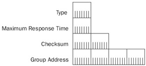
Figure 9-4: The structure of the IGMPv2 message.
The IGMPv2 header contains the following fields:
- TypeIGMPv2 combines the IGMPv1 4-bit Version field and IGMPv1 4-bit Type field into a single 8-bit Type field. Table 9-3 lists the Type field values.
Table 9-3: Values of the IGMPv2 Type Field Type
Message
17 (0x11)
Host Membership QueryThe previous Version 0x1 and Type 0x1 are combined to form 0x11, or 17.
18 (0x12)
IGMPv1 Host Membership ReportThe previous Version 0x1 and Type 0x2 are combined to form 0x12, or 18.
22 (0x16)
IGMPv2 Host Membership ReportThe IGMPv2 Host Membership Report has the same function as the IGMPv1 Host Membership Report and is intended to be received by only IGMPv2-capable multicast routers.
23 (0x17)
Leave Group Message
- Maximum Response TimeThe IGMPv1 Unused field is used in IGMPv2 Membership Query messages (either General or Group-Specific) to store a maximum time in tenths of a second within which a host must respond to the query. The maximum response time becomes the maximum value of the report delay timer for subnet host members.
- ChecksumA 2-byte field that stores a checksum on the 8-byte IGMP message.
- Group AddressSet to 0.0.0.0 for the general Host Membership Query and set to the specific group address for all other IGMPv2 message types.
Table 9-4 summarizes the addresses used in IGMPv2 Group-Specific Host Membership Query and Group Leave messages.
|
Group-Specific Query |
Group Leave |
|
|---|---|---|
|
Source IP Address (IP header) |
Router IP Address |
Host IP Address |
|
Destination IP Address (IP header) |
Group IP Address |
224.0.0.2 |
|
Group Address |
Group IP Address |
Group IP Address |
Network Monitor Example
The following Network Monitor trace (Capture 09-03 in the Captures folder on the companion CD-ROM) shows an IGMPv2 Host Membership Report message for a host registering the group address 239.255.255.252:
+ Frame: Base frame properties
 ETHERNET: ETYPE = 0x0800 : Protocol = IP: DOD Internet Protocol
 ETHERNET: Destination address : 01005E7FFFFC
 ETHERNET: .......1 = Group address
 ETHERNET: ......0. = Universally administered address
 + ETHERNET: Source address : 0060083E4607
 ETHERNET: Frame Length : 46 (0x002E)
 ETHERNET: Ethernet Type : 0x0800 (IP: DOD Internet Protocol)
 ETHERNET: Ethernet Data: Number of data bytes remaining = 32 (0x0020)
 IP: ID = 0x1A26; Proto = IGMP; Len: 32
 IP: Version = 4 (0x4)
 IP: Header Length = 24 (0x18)
 IP: Precedence = Routine
 IP: Type of Service = Normal Service
 IP: Total Length = 32 (0x20)
 IP: Identification = 6694 (0x1A26)
 IP: Flags Summary = 0 (0x0)
 IP: .......0 = Last fragment in datagram
 IP: ......0. = May fragment datagram if necessary
 IP: Fragment Offset = 0 (0x0) bytes
 IP: Time to Live = 1 (0x1)
 IP: Protocol = IGMP - Internet Group Management
 IP: Checksum = 0x07ED
 IP: Source Address = 10.1.8.200
 IP: Destination Address = 239.255.255.252
 IP: Option Fields
 IP: Unrecognized Option
 IP: Option Type = 0x94
 IP: Option Length = 4 (0x4)
 IP: Option data: Number of data bytes remaining = 2 (0x0002)
 IP: Data: Number of data bytes remaining = 8 (0x0008)
 IP: Padding: Number of data bytes remaining = 14 (0x000E)
 IGMP: Version 2 Membership Report
 IGMP: Type = Version 2 Membership Report
 IGMP: Unused = 0 (0x0)
 IGMP: Checksum = 0xFA02
 IGMP: Group Address = 239.255.255.252
Notice the existence of the IP Router Alert option (Option Type 0x94) that is used to inform the router that further processing of the IP header is required. For more information on the IP Router Alert option, see Chapter 5, "Internet Protocol (IP) Basics."
IGMP Version 3 (IGMPv3)
IGMPv3 supports multicast source-specific reports and queries. With IGMPv1 and IGMPv2, multicast group members report membership and routers query for membership without regard to the source of the multicast traffic. IGMPv3 allows you to have multiple sources for multicast traffic, which can be beneficial when you are multicasting a video session across an enterprise organization. Rather than having a single source of the multicast packets that comprise the video broadcast, you can have multiple sources distributed regionally. Then, multicast hosts can join the group and specify a multicast source that is topologically closest to them (a regional source).
| More Info |
IGMPv3 is described in RFC 3376, which is available in the RFC folder of the companion CD-ROM. |
When an IGMPv3 host sends a Host Membership Report message, it can specify the multicast group and either the list of multicast sources from which the host can receive the multicast packets (the include list) or a list of the multicast sources from which the host must not receive multicast packets (the exclude list). Multicast routers and multicast routing protocols use the list of sources to include or exclude in the IGMPv3 Host Membership Report message to promote the forwarding of multicast packets from included sources and prevent the forwarding and delivery of multicast packets from excluded sources.
In IGMPv3, the Host Membership Query message is modified to allow an IGMPv3 router to send source- and-group-specific queries. An IGMPv3 host uses a new Host Membership Report message to send source-specific reports.
IGMPv3 Host Membership Query
The IGMPv3 Host Membership Query message is for a group- and source-specific query, sent by an IGMPv3 router to determine if there are any group members in the indicated group address for traffic from one of the sources in the source list. The IGMPv3 Host Membership Query message uses the same IGMP Type number (0x11) and has the same format as the IGMPv2 Host Membership Query message. However, there are additional fields after the Group Address field that allow the router to specify querying parameters and list the sources of the multicast group being queried. These additional fields are only included for an IGMPv3 group- and source-specific query.
Beyond the Group Address field, the IGMPv3 Host Membership Query message contains the following fields:
- ReservedA 4-bit field set to 0 by the sender that is ignored by the receiver.
- Suppress Router-Side ProcessingA 1-bit field that, when set to 1, indicates that receiving routers are to suppress normal processing when receiving a query message.
- Querier's Robustness VariableA 3-bit field that indicates the robustness variable of the sending router. The robustness variable is a measure of how many IGMP packets can be lost without recovery. IGMP can recover from Querier's Robustness Variable - 1 lost IGMP packets.
- Querier's Query IntervalA 1-byte field that indicates the number of seconds between query messages of the sending router.
- Number Of SourcesA 2-byte field that indicates the number of sourceaddresses included in the message.
- Source AddressA 4-byte field that indicates the unicast IP address of a multicast source.
Figure 9-5 shows the structure of the IGMPv3 Host Membership Query message.
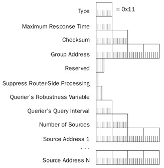
Figure 9-5: The structure of the IGMPv3 Host Membership Query message.
IGMPv3 Host Membership Report
The IGMPv3 Host Membership Report message contains one or more group records and is sent to the multicast address 224.0.0.22, a reserved multicast address for all IGMPv3-capable multicast routers. Each group record contains the group address and the list of sources to either include or exclude.
The IGMPv3 Host Membership Report message contains the following fields:
- TypeA 1-byte field set to 0x22 to indicate an IGMPv3 Host MembershipReport message.
- ReservedA 1-byte field set to 0 by the sender and ignored by the receiver.
- ChecksumA 2-byte field that stores a checksum on the IGMPv3 message.
- ReservedA 2-byte field set to 0 by the sender and ignored by the receiver.
- Number Of RecordsA 2-byte field that indicates the number of group records contained in the message.
- Group Record A variable-sized field that contains a multicast address on which the sending host is listening and either an include list or exclude list of sources.
Figure 9-6 shows the structure of the IGMPv3 Host Membership Report message.
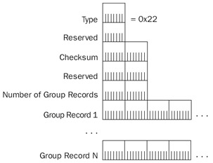
Figure 9-6: The structure of the IGMPv3 Host Membership Report message.
The IGMPv3 Host Membership Report message group record contains the following fields:
- Record TypeA 1-byte field that indicates the type of group record and whether the list of sources is an inclusion or exclusion list.
- Auxiliary Data LengthA 1-byte field that indicates the number of bytes of auxiliary data included in the group record.
- Number Of SourcesA 2-byte field that indicates the number of multicast sources contained in the group record.
- Multicast AddressA 4-byte field that indicates the IP address of the group that the host is joining.
- Source AddressA 4-byte field that indicates the unicast IP address of a multicast source.
- Auxiliary DataA variable-sized field that contains additional data for this group record.
Figure 9-7 shows the structure of an IGMPv3 Host Membership Report message group record.
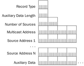
Figure 9-7: The structure of the IGMPv3 Host Membership Report message group record.
The Windows Server 2003 Family and IGMP
The Windows Server 2003 family supports IP multicast sending, receiving, and forwarding through the TCP/IP protocol and the Routing and Remote Access service.
TCP IP Protocol
TCP/IP for the Windows Server 2003 family supports IP multicast traffic in the following ways:
- To support host reception of IP multicast traffic, TCP/IP for the Windows Server 2003 family is an IGMPv3-capable host.
- To support host transmission and reception of IP multicast traffic, TCP/IP for the Windows Server 2003 family supports the mapping of IP multicast addresses to MAC addresses for Ethernet and FDDI network adapters as described in RFC 1112. For Token Ring network adapters, all IP multicast traffic by default is mapped to the Token Ring functional address of 0x-C0-00-00-04-00-00.
- To support the forwarding of IP multicast traffic, TCP/IP for the Windows Server 2003 family supports multicast forwarding based on the entries in the TCP/IP multicast forwarding table and the setting of the EnableMulticastForwarding registry setting. You can view the contents of the TCP/IP multicast forwarding table from the Routing and Remote Access administrative tool or from the display of the netsh routing ip show mfe command.
In the Windows Server 2003 family, TCP/IP behavior for IP multicast forwarding is controlled by the following registry setting:
EnableMulticastForwarding
Location:
HKEY_LOCAL_MACHINESYSTEMCurrentControlSetServicesTcpipParameters
Data Type: REG_DWORD
Valid Range: 0-1
Default: 0
Present by Default: No
EnableMulticastForwarding enables (when set to 1) or disables (when set to 0) the forwarding of IP multicast traffic. By default, multicast forwarding is disabled.
Routing and Remote Access Service
In the Windows Server 2003 family, the Routing and Remote Access service functions as a limited multicast forwarder using IGMPv1, IGMPv2, or IGMPv3 to track local group membership. Because IGMP is not a true multicast routing protocol, routers running a member of the Windows Server 2003 family can support only limited multicast configurations. For more information on recommended configurations, see the Internetworking Guide in the Microsoft Windows Server 2003 Resource Kit.
In the Routing and Remote Access service, IGMP is implemented as a routing protocol component added and configured through the Routing and Remote Access administrative tool. After running the Routing and Remote Access Server Setup Wizard, the IGMP routing protocol component is automatically added. Add individual routing interfaces to the IGMP routing protocol and configure them for either IGMP router mode or IGMP proxy mode.
Interfaces in IGMP Router Mode
An interface in IGMP router mode acts as an IGMP-capable IP multicast forwarder and performs the following actions:
- Places the network adapter in multicast promiscuous modeIf the network interface is a broadcast network type such as Ethernet or FDDI, the network adapter is placed in multicast promiscuous mode. If the network adapter does not support multicast promiscuous mode, an event is logged in the system event log.
- Manages local subnet multicast group membershipThe routing interface uses IGMP to listen for IGMP Host Membership Report and Leave Group messages, to elect an IGMP querier, and to send General and Group-Specific Host Membership Query messages.
- Updates the TCP/IP multicast forwarding tableBased on ongoing group membership for the interface, IGMP in conjunction with other components of the Routing and Remote Access service maintains the TCP/IP multicast forwarding table.
Interfaces in IGMP Proxy Mode
An interface in IGMP proxy mode acts as an IGMP-capable IP multicast proxy host for hosts on IGMP router mode interfaces and performs the following functions:
- Forwards IGMP Host Membership ReportsIGMP Host Membership Report messages received on IGMP router mode interfaces are forwarded on the IGMP proxy mode interface. The forwarded Host Membership Report messages have a TTL of 1. The received Host Membership Reports are not forwarded using the entries in the TCP/IP multicast forwarding table.
- Adds multicast MAC addresses to the network adapter tableFor each group address registered by proxy, the corresponding multicast MAC address is added to the table of interesting MAC addresses on the network adapter (for local area network [LAN] technologies such as Ethernet and FDDI). The network adapter is not placed in promiscuous mode unless the network card cannot support listening to all required multicast MAC addresses. Nonlocal IP multicast traffic received on the IGMP proxy mode interface is passed to the TCP/IP protocol for multicast forwarding.
- Updates the TCP/IP multicast forwarding tableTo facilitate the forwarding of multicast traffic from a multicast source on an IGMP router mode interface to a group member downstream from the IGMP proxy mode interface, the IGMP routing protocol adds entries to the TCP/IP multicast forwarding table so that all nonlocal IP multicast traffic received on IGMP router mode interfaces is forwarded over the IGMP proxy mode interface. The IGMP proxy mode interface forwards all nonlocal multicast traffic received from IGMP router mode interfaces regardless of whether or not there are group members present downstream from the IGMP proxy mode interface.
IGMP proxy mode is designed to connect a router running a member of the Windows Server 2003 family to a fully capable IP multicast internetwork, as Figure 9-8 shows. A good example of this is the connection of a single router intranet to the MBONE. IGMP proxy mode is enabled on a single interface connected to the multicast-enabled internetwork.
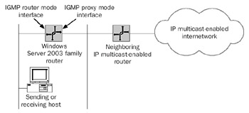
Figure 9-8: The use of IGMP router mode and proxy mode to connect a single router intranet to an IP multicast-enabled internetwork.
The combination of IGMP router mode interfaces and the IGMP proxy mode interface allows the sending and receiving of IP multicast traffic for hosts on a peripheral network segment using a router running a member of the Windows Server 2003 family.
Multicast Group Members on IGMP Router Mode Interfaces
Host members on IGMP router mode interfaces receive host group traffic through the following process:
- A host sends an IGMP Host Membership Report message on the local subnet.
- The router updates its multicast forwarding table with the appropriate entry.
- The IGMP routing protocol uses the NDISRequest( ) function to add the multicast MAC address corresponding to the IP multicast address to the table of interesting MAC addresses on the network adapter on which IGMP proxy mode is enabled.
- The router forwards the IGMP Host Membership Report message on the IGMP proxy mode interface.
- The neighboring IP multicast-enabled router receives the IGMP Host Membership Report message, makes the appropriate changes to its multicast forwarding table, and informs downstream IP multicast-enabled routers using multicast routing protocols that a host member exists on the IGMP proxy mode interface network segment.
Routers of the IP multicast-enabled internetwork forward IP multicast traffic sent to the host group to the neighboring IP multicast-enabled router, which forwards the traffic on the IGMP proxy mode interface network segment. The IGMP proxy mode interface receives the multicast traffic and submits it to the TCP/IP multicast forwarding process. Basedon the entries in the multicast forwarding table, the IP multicast traffic is forwarded on the IGMP router mode interface connected to the network segment containing thehost member.
Multicast Sources on IGMP Router Mode Interfaces
The multicast traffic of multicast sources on IGMP router mode interfaces is forwarded through the following process:
- A multicast source host sends nonlocal IP multicast traffic to a specific group address.
- The IGMP router mode interface receives the multicast traffic.
- For the first multicast packet, the IGMP routing protocol adds an entry to the TCP/IP multicast forwarding table, indicating that there are host members present on the IGMP proxy mode interface.
- The multicast traffic is passed to the multicast forwarding process. Based on the entries in the multicast forwarding table, the multicast traffic is forwarded on the IGMP proxy mode interface.
- The neighboring IP multicast-enabled router receives the IP multicast traffic and passes it to the multicast forwarding process. Based on the entries in the multicast forwarding table of the IP multicast-enabled router, the multicast packet is either forwarded to host members (local or downstream) or silently discarded.
Summary
IGMP provides a mechanism for hosts to register their interest in receiving IP multicast traffic sent to a specific group address (the Host Membership Report message), for hosts to indicate that they are no longer interested in receiving IP multicast traffic sent to a specific group address (the Leave Group message), and for routers to query the mem
Part I - The Network Interface Layer
- Local Area Network (LAN) Technologies
- Wide Area Network (WAN) Technologies
- Address Resolution Protocol (ARP)
- Point-to-Point Protocol (PPP)
Part II - Internet Layer Protocols
- Internet Protocol (IP) Basics
- Internet Protocol (IP) Addressing
- Internet Protocol (IP) Routing
- Internet Control Message Protocol (ICMP)
- Internet Group Management Protocol (IGMP)
- Internet Protocol Version 6 (IPv6)
Part III - Transport Layer Protocols
- User Datagram Protocol
- Transmission Control Protocol (TCP) Basics
- Transmission Control Protocol (TCP) Connections
- Transmission Control Protocol (TCP) Data Flow
- Transmission Control Protocol (TCP) Retransmission and Time-Out
Part IV - Application Layer Protocols and Services
- Dynamic Host Configuration Protocol (DHCP) Server Service
- Domain Name System (DNS)
- Windows Internet Name Service (WINS)
- File and Printer Sharing
- RADIUS and Internet Authentication Service
- Internet Information Services (IIS) and the Internet Protocols
- Internet Protocol Security (IPSec)
- Virtual Private Networks (VPNs)
EAN: N/A
Pages: 216
