Point-to-Point Protocol (PPP)
Overview
As first introduced in Chapter 2, "Wide Area Network (WAN) Technologies," PPP is a standard for using point-to-point network links that provides the following:
- A Data Link Layer encapsulation method that supports multiple protocolssimultaneously on the same link.
- A protocol for negotiating the Data Link Layer characteristics of the point-to-point connection named the Link Control Protocol (LCP).
- A series of protocols for negotiating the Network Layer properties of Network Layer protocols over the point-to-point connection named Network Control Protocols (NCPs). For example, RFCs 1332 and 1877 describe the Internet Protocol Control Protocol (IPCP), the NCP for IP. IPCP is used to negotiate an IP address, the addresses of name servers, and the use of the Van Jacobsen TCP compression protocol.
Chapter 2 discusses only the Data Link Layer encapsulation. This chapter describes LCP and the set of NCPs needed for PPP and IP connectivity.
| More Info |
PPP is described in RFC 1661, which can be found in the Rfc folder on the companion CD-ROM. |
PPP Connection Process
There are four phases to a PPP connection, all of which must be completed before data can be sent on the connection. The four phases are the following:
- PPP configuration using LCP
- Authentication using a PPP authentication protocol (optional)
- Callback
- Protocol configuration using NCPs
Phase 1: PPP Configuration Using LCP
In the first phase of the PPP connection process, PPP connection parameters are configured using LCP. With LCP, the PPP peers negotiate a common set of parameters that are used for all subsequent phases of the PPP connection and for sending data. Some of the communication parameters that are negotiated are the following:
- The maximum receive unit (MRU), the largest PPP frame that can be sent on the connection
- Whether the Address and Control fields in the PPP header are used (for links that use the High-Level Data Link Control [HDLC] encapsulation that is described in RFC 1662)
- Whether the Protocol field in the PPP header can be compressed from 2 bytes to 1 byte
- The PPP authentication protocol to be used during the authentication phase
- Whether Multilink PPP (MP) is used
For more information, see the section entitled "Link Control Protocol," later in this chapter.
Phase 2: Authentication
After LCP negotiation, the authentication process using the PPP authentication protocol negotiated during phase 1 is performed. This process is specific to the PPP authentication protocol used. For more information, see the section entitled "PPP Authentication Protocols," later in this chapter.
Phase 3: Callback
If the authentication process succeeds and callback behavior is configured, the answering PPP peer terminates the connection and initiates a connection to the original calling PPP peer, a feature of PPP implementations known as callback. The PPP implementation in the Microsoft Windows Server 2003 family and Windows XP uses the Callback Control Protocol (CBCP) to complete the callback phase. For more information, see the section entitled "Callback and the Callback Control Protocol," later in this chapter.
Phase 4: Protocol Configuration Using NCPs
After PPP is configured, the original initiating PPP peer is authenticated, and callback is done (optional and only if configured), individual data protocols and ancillary PPP services such as encryption and compression are configured using NCPs. For more information, see the section entitled "Network Control Protocols," later in this chapter.
PPP Connection Termination
After a PPP connection is established, it can be terminated at any time by either the connection-initiating or connection-receiving PPP peer. PPP connections can be terminated by user action, connection policy action (such as terminating the connection after a specific amount of idle time), or link failure. When the PPP connection terminates, PPP informs the data protocols that were operating over it that the point-to-point interface is no longer available.
Link Control Protocol
LCP, described in RFC 1661, is a simple protocol to configure a common set of PPP connection parameters (for phase 1 of the PPP connection). It is also used by NCPs to configure specific data protocol configuration parameters (for phase 2 of the PPP connection). LCP uses the PPP Protocol ID 0xC0-21. Figure 4-1 shows an LCP frame.
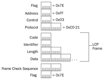
Figure 4-1: The structure of an LCP frame.
The fields in the LCP frame are defined as follows:
- CodeA 1-byte field that identifies the type of LCP message
- IdentifierA 1-byte field that identifies a specific pair of LCP messages: the request and the response
- LengthA 2-byte length field that indicates the size of the LCP message in bytes
- DataA variable-sized field that contains the LCP frame type-specific data
Table 4-1 lists the LCP frame types described in RFC 1661.
|
Code |
Frame Type |
Description |
|---|---|---|
|
1 |
Configure-Request |
Sent to open or reset a PPP connection. |
|
2 |
Configure-Ack |
Sent to indicate when the last Configure-Request frame contains options with acceptable values. The LCP negotiation is complete when each PPP peer both sends and receives Configure-Ack frames. |
|
3 |
Configure-Nak |
Sent to indicate that the LCP options in the Configure- Request are recognized, but some option values are not acceptable. |
|
4 |
Configure-Reject |
Sent to indicate that the LCP options in the Configure- Request frame are either not recognized or not acceptable. |
|
5 |
Terminate-Request |
Sent to close the PPP connection. |
|
6 |
Terminate-Ack |
Sent to respond to the Terminate-Request message. |
|
7 |
Code-Reject |
Sent when the LCP Code field of a received LCP frame is unknown. |
|
8 |
Protocol-Reject |
Sent when the PPP Protocol field of a received PPP frame is unknown. |
|
9 |
Echo-Request |
Sent to test the PPP connection. |
|
10 |
Echo-Reply |
Sent in response to an Echo-Request frame. |
|
11 |
Discard-Request |
Sent to test outbound data on the link. |
| Note |
The LCP Echo-Request and Echo-Reply messages are not related to the Internet Control Message Protocol (ICMP) Echo and Echo Reply messages. |
LCP Options
The data portion of an LCP message consists of one or more LCP options for the Configure-Request, Configure-Ack, Configure-Nak, and Configure-Reject LCP frames. An LCP option is formatted in type-length-value (TLV) format. A 1-byte Type field indicates the option type, a 1-byte Length field indicates the length in bytes of the entire option, and the Option Data field contains the data of the option. Figure 4-2 shows an LCP message that contains LCP options.
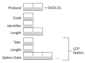
Figure 4-2: The structure of an LCP frame containing LCP options.
Table 4-2 lists common LCP options used by PPP peers that run Microsoft operating systems.
|
Option Name |
Type |
Length |
Description |
|---|---|---|---|
|
Maximum Receive |
1 |
4 |
Used to indicate the maximum size of the PPP frame Unit (MRU) that can be supported on the connection. The maxi- mum size is 65,535. The default MRU is 1500. |
|
Asynchronous Control |
2 |
6 |
Contains a 4-byte bit map indicating which ASCIICharacter Map (ACCM) control characters from 0x0 to 0x20 use character escapes for asynchronous links. Character escapes are used to distinguish data from control characters sent on the connection. By default, character escapes are used for all 32 control characters. |
|
Authentication Protocol |
3 |
5 or 6 |
Used to indicate the PPP authentication protocol for the authentication phase to verify the iden- tity. For Microsoft PPP peers, the values are 0xC2-27 for Extensible Authentication Protocol (EAP), 0xC2-23-80 for Microsoft Challenge Handshake Authentication Protocol (MS-CHAP), 0xC2-23-81 for MS-CHAP version 2, 0xC2-23-05 for Message Digest version 5 Challenge Handshake Authentication Pro- tocol (MD5-CHAP), 0xC0-27 for Shiva Password Authentication Protocol (SPAP), and 0xC0-23 for Password Authentication Protocol (PAP). |
|
Magic Number |
5 |
6 |
Contains a random number to distinguish a PPP peer and detect looped back lines. |
|
Protocol Compression |
7 |
2 |
A flag option that indicates that the sender wants to use a 1-byte Protocol field for PPP data frames. PPP control frames using LCP or NCPs still use a 2-byte Protocol field. |
|
Address and Control Field Compression |
8 |
2 |
A flag option that indicates that the sender wants to remove the Address and Control fields from the HDLC-based PPP header. |
|
Callback |
13 |
3 |
Used to determine the callback behavior for the connection. For PPP clients and servers running a modern 32-bit or 64-bit Windows operating system, CBCP is used to determine callback behavior. |
Additional LCP options are defined in RFC 1661.
LCP Negotiation Process
LCP is used to negotiate the parameters of PPP when sending data in a single direction on the PPP connection. Different PPP parameters could be negotiated in the two different directions of data travel on a PPP connection. Therefore, each PPP peer must perform a separate LCP negotiation. An LCP negotiation is used by a PPP peer to establish how the other PPP peer should send data to it. Each LCP negotiation is a series of LCP frames to negotiate the use of a common set of parameters for data sent by the PPP peer on the other side of the PPP connection from the LCP negotiation initiator. For two PPP peers, Peer A and Peer B, Peer A initiates an LCP negotiation for the data to be sent by Peer B and Peer B initiates a separate LCP negotiation for the data to be sent by Peer A.
An individual LCP negotiation consists of an initial set of LCP options using the LCP Configure-Request message. The specific set of LCP options is negotiated using Configure-Nak and Configure-Reject messages and finally confirmed with a Configure-Ack message. Both negotiations occur simultaneously, making it more difficult to read the captures of PPP connection establishments.
When a PPP peer sends a Configure-Request message, the response is one of the following:
- Configure-Nak messageSent because one or more options in the Configure-Request message have unacceptable values
- Configure-Reject messageSent because one or more of the options are either unknown or non-negotiable
- Configure-Ack messageSent because all of the options have acceptablevalues
When the Configure-Reject message is received, the unknown or non-negotiable options are removed from the list of LCP options being configured by the initiating PPP peer and a new Configure-Request message is sent. When the Configure-Nak message is received, the included options are set to their indicated values and a new Configure-Request message is sent. When the Configure-Ack message is received, the LCP negotiation is complete. For each new Configure-Request message, the Identifier field in the LCP header is changed to a new value to match a sent Configure-Request message with its response.
For example, the following is a sample LCP negotiation using fictional options:
- Peer 1 sends a Configure-Request message requesting that options A and B (both flag options) be used, that option C be set to 5000, and that option D be set to 1.
- Because Peer 2 does not understand option B, it sends a Configure-Rejectmessage containing option B.
- Peer 1 sends a new Configure-Request message requesting that option A be used, that option C be set to 5000, and that option D be set to 1.
- Because Peer 2 prefers that option C be set to 1500 and option D be set to 3, it sends a Configure-Nak message containing option C set to 1500 and option D set to 3.
- Peer 1 sends a new Configure-Request message requesting that option A be used, that option C be set to 1500, and that option D be set to 3.
- Because all the options in the Configure-Request message contain knownoptions with preferred values, Peer 2 sends a Configure-Ack message.
The following frames (Frame 1 through Frame 8) from the Network Monitor trace in Capture 04-01 (in the Captures folder on the companion CD-ROM) summarize an LCP negotiation between a remote access client computer running Microsoft Windows XP and a remote access server computer running a member of the Windows Server 2003 family. The summary frames have been indented for readability.
Frame Time Src MAC Addr Dst MAC Addr Protocol Description
1 7.060152 RECV RECV LCP Config Req Packet,
 Ident = 0x00, Length = 50
2 7.060152 SEND SEND LCP Config Req Packet,
 Ident = 0x00, Length = 58
3 7.060152 SEND SEND LCP Config Ack Packet,
 Ident = 0x00, Length = 50
4 7.130253 RECV RECV LCP Config Reject Packet,
 Ident = 0x00, Length = 8
5 7.130253 SEND SEND LCP Config Req Packet,
 Ident = 0x01, Length = 54
6 7.220383 RECV RECV LCP Config No Ack Packet,
 Ident = 0x01, Length = 9
7 7.220383 SEND SEND LCP Config Req Packet,
 Ident = 0x02, Length = 55
8 7.320527 RECV RECV LCP Config Ack Packet,
 Ident = 0x02, Length = 55
Due to the architecture of PPP in Windows XP and the Windows Server 2003 family, PPP frames captured by Network Monitor are displayed as an Ethernet frame with the PPP Protocol ID field taking the place of the EtherType field. The source and destination media access control (MAC) addresses are set to either SEND or RECV, depending whether the frame was sent to (set to SEND) or received from (set to RECV) the computer on which the Network Monitor capture was taken. In this instance, the Network Monitor capture was taken on the remote access server. Therefore, the RECV frames were sent by the remote access client and the SEND frames were sent by the remote access server.
For this trace, Frames 1 and 3 correspond to the LCP negotiation initiated by the remote access client for the frames sent by the remote access server. Frame 2 and frames 4 through 8 correspond to the LCP negotiation initiated by the remote access server for the frames sent by the remote access client.
PPP Authentication Protocols
After LCP negotiation is complete, the authentication protocol agreed on during LCP negotiation using LCP option 3 is used to establish the identity and credentials of the PPP peer that is requesting the PPP connection, typically a remote access client (for remote access dial-up or virtual private network [VPN] connections) or a calling router (for router-to-router dial-up or VPN connections). The authentication process is phase 2 of the PPP connection establishment.
The Windows Server 2003 family and Windows XP support the following PPPauthentication protocols:
- Password Authentication Protocol (PAP)
- Shiva Password Authentication Protocol (SPAP)
- Challenge Handshake Authentication Protocol (CHAP)
- Microsoft Challenge Handshake Authentication Protocol (MS-CHAP)
- MS-CHAP version 2 (MS-CHAP v2)
- Extensible Authentication Protocol (EAP)
Note SPAP is a proprietary authentication protocol and is not described in this chapter.
PAP
PAP is a very simple, plaintext authentication protocol described in RFC 1334. The entire PAP negotiation consists of the following messages:
- The connection-initiating PPP peer (the calling peer) sends a PAP Authenticate-Request message to the authenticating PPP peer (the answering peer), which contains the calling peer's user name and password in plaintext.
- The answering peer validates the user name and password. If the user name and password are correct, the answering peer sends a PAP Authenticate-Ack message. If not, the answering peer sends a PAP Authenticate-Nak message.
Obviously, PAP is not a secure authentication protocol. A malicious user that can capture the PAP frames sent between the calling peer and answering peer can view the contents of the PAP Authenticate-Request message to determine the user name and password of a valid user account. The use of PAP is highly discouraged and is only included in Windows XP and the Windows Server 2003 family for troubleshooting and compatibility with PPP peers that do not support more secure authentication protocols.
PPP peers negotiate the use of PAP during phase 1 by specifying LCP option 3 (authentication protocol) and the authentication protocol 0xC0-23. After phase 1 negotiation is complete, PAP messages use the PPP protocol ID 0xC0-23.
Figure 4-3 shows the PAP Authenticate-Request message.
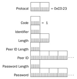
Figure 4-3: The structure of the PAP Authenticate-Request message.
The following are the fields in the PAP Authenticate-Request message:
- CodeA 1-byte field that identifies the type of PAP message. For Authenticate-Request messages, the value of the Code field is set to 1.
- IdentifierA 1-byte field that is used to identify a pair of PAP messages: the request and the response. The calling peer sets the value of the Identifier field.
- LengthA 2-byte field that indicates the size of the PAP message in bytes.
- Peer ID LengthA 1-byte field that indicates the size of the Peer ID field in bytes.
- Peer IDA variable-sized field that contains the user name of the calling peer.
- Password LengthA 1-byte field that indicates the size of the Password field in bytes.
- PasswordA variable-sized field that contains the password of the calling peer.
Figure 4-4 shows the PAP Authenticate-Ack and Authenticate-Nak messages.
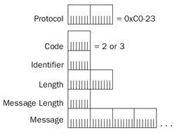
Figure 4-4: The structure of the PAP Authenticate-Ack and Authenticate-Nak messages.
The following are the fields in the Authenticate-Ack and Authenticate-Nak messages:
- CodeFor an Authenticate-Ack message, the value of the Code field is set to 2. For an Authenticate-Nak message, the value of the Code field is set to 3.
- IdentifierA 1-byte field that is set to the value of the Identifier field in the corresponding Authenticate-Request message.
- LengthA 2-byte field that indicates the size of the PAP message in bytes.
- Message LengthA 1-byte field that indicates the size of the Message field in bytes.
- MessageA variable-sized field that contains a message for the calling peer. The Message field is not used by Microsoft operating systems. Some PPP implementations display the message text to the user who is connecting.
Capture 04-02 in the Captures folder on the companion CD-ROM contains an example of a PAP authentication.
CHAP
CHAP is a more secure authentication protocol, described in RFC 1994, that uses a challenge–response exchange of messages to validate that the calling peer has knowledge of the user's password. The password itself is never sent. Although more secure than PAP, CHAP does not provide mutual authentication. The calling peer authenticates to the answering peer but the answering peer does not authenticate to the calling peer. Without mutual authentication, a calling peer is unable to determine whether it is calling a valid answering peer.
When the use of CHAP is negotiated during phase 1, an algorithm that is used to provide proof of knowledge of the user password is also specified. For the Message Digest-5 (MD5) algorithm, the LCP option data for the authentication protocol contains the CHAP authentication protocol (0xC2-23) and the MD-5 algorithm (0x05). CHAP messages use the PPP Protocol ID 0xC2-23.
CHAP authentication using MD5 consists of the following three messages:
- The answering peer sends a CHAP Challenge message that contains a CHAP session ID (the value of the Identifier field), a challenge string, and the name of the answering peer.
- The calling peer sends a CHAP Response message that contains the user name of the calling peer and an MD5 hash of the CHAP session ID, the challenge string, and the user's password.
- The answering peer calculates its own MD5 hash of the CHAP session ID, the challenge string, and user password and compares the result with the MD5 hash in the CHAP Response message. If the two hashes are identical, the answering peer sends a CHAP Success message. If not, the answering peer sends a CHAP Failure message and the connection is terminated.
Figure 4-5 shows the CHAP Challenge and CHAP Response messages.
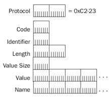
Figure 4-5: The structure of the CHAP Challenge and CHAP Response messages.
The following are the fields in the CHAP Challenge and CHAP Response messages:
- CodeA 1-byte field that identifies the type of CHAP message. For a CHAP Challenge message, the value of the Code field is set to 1. For a CHAP Response message, the value of the Code field is set to 2.
- IdentifierA 1-byte field that is used to identify a pair or sequence of CHAP messages (the CHAP session ID). The calling peer sets the value of the Identifier field.
- LengthA 2-byte field that indicates the size of the CHAP message in bytes.
- Value SizeA 1-byte field that indicates the size of the Value field.
- ValueA variable-sized field that contains either the challenge string for the CHAP Challenge message or the MD5 hash for the CHAP Response message.
- NameA variable-sized field that contains the name of either the answering peer for the CHAP Challenge message or the calling peer for the CHAPResponse message.
Figure 4-6 shows the structure of the CHAP Success and CHAP Failure messages.
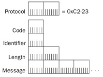
Figure 4-6: The CHAP Success and CHAP Failure message structure.
The following are the fields in the CHAP Success and CHAP Failure messages:
- CodeFor a CHAP Success message, the value of the Code field is set to 3. For a CHAP Failure message, the value of the Code field is set to 4.
- IdentifierA 1-byte field that is used to indicate the CHAP session ID.
- LengthA 2-byte field that indicates the size of the CHAP message in bytes.
- MessageA variable-sized field that contains a message for the calling peer. The Message field is optional and is not used by Microsoft operating systems.
Capture 04-03 in the Captures folder on the companion CD-ROM contains an example of an MD5-CHAP authentication.
MS CHAP
To calculate the MD5 hash for CHAP, the user's password must be available in plaintext form. By default, Microsoft operating systems do not store a plaintext version of user passwords. Instead, they store a Message Digest-4 (MD4) hash of the password. MS-CHAP is a CHAP-based authentication protocol, described in RFC 2433, that is designed to work with the MD4 hash of account passwords to validate calling peer credentials. Like MD5-CHAP, MS-CHAP does not require the passwords to be sent and does not provide mutual authentication.
When MS-CHAP is negotiated during phase 1, the LCP option data for the authentication protocol contains the CHAP authentication protocol (0xC2-23) and the MS-CHAP algorithm (0x80). MS-CHAP messages use the PPP Protocol ID 0xC2-23.
MS-CHAP authentication consists of the following three messages:
- The answering peer sends a CHAP Challenge message that contains a challenge string and the name of the answering peer.
- The calling peer sends an MS-CHAP Response message that contains the user name of the calling peer and an encrypted response based on the challenge string and the MD4 hash of the user's password.
- The answering peer calculates its own encrypted result based on the challenge string and the MD4 hash of the user's password and compares it to the version in the MS-CHAP Response message. If the two results are identical, the answering peer sends a CHAP Success message. If not, the answering peer sends a CHAP Failure message.
Figure 4-7 shows the MS-CHAP Response message.
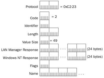
Figure 4-7: The structure of the MS-CHAP Response message.
The following are the fields in the MS-CHAP Response message:
- CodeFor an MS-CHAP Response message, the value of the Code field is set to 2.
- IdentifierA 1-byte field that is set to the value of the Identifier field in the original CHAP Request message.
- LengthA 2-byte field that indicates the size of the MS-CHAP Response message in bytes.
- Value SizeA 1-byte field that indicates the size of the CHAP Value field. For the MS-CHAP Response message, the CHAP Value field consists of the LAN Manager Response, the Windows NT Response, and the Flags fields and is a fixed size of 49 bytes.
- LAN Manager ResponseA 24-byte field that contains the LAN Manager–encoded response. The use of this field is deprecated and should be set to 0.
- Windows NT ResponseA 24-byte field that contains the Windows NT–encoded response.
- FlagsA 1-byte field that indicates, when set to 1, that the Windows NTResponse field has a value and should be preferred over the value in the LAN Manager Response field. Because the use of the LAN Manager Response field is deprecated, this field is always set to 1.
- NameA variable-sized field that contains the name of the calling peer.
Capture 04-04 in the Captures folder on the companion CD-ROM contains an example of an MS-CHAP authentication.
MS-CHAP also allows the answering peer to indicate specific error conditions in the Message field of the CHAP Failure message. One of the errors is ERROR_PASSWD_EXPIRED. When the calling peer receives this error indication, it can submit an MS-CHAP Change Password message to submit a new password for the account corresponding to the account of the user name. There are two versions of the Change Password message: Version 1 is used by older Microsoft operating systems and its use is deprecated due to its weak security. Version 2 is used by newer Microsoft operating systems, such as Windows XP and the Windows Server 2003 family. For more information about these messages, see RFC 2433.
MS CHAP v2
MS-CHAP v2 is a CHAP-based authentication protocol described in RFC 2759 that, unlike both CHAP and MS-CHAP, provides mutual authentication. With MS-CHAP v2, the answering peer receives confirmation that the calling peer has knowledge of the user account's password and the calling peer receives confirmation that the answering peer has knowledge of the user account's password. To provide for this mutual authentication, both peers issue a challenge and must receive a valid response or the connection is terminated.
When MS-CHAP v2 is negotiated during phase 1, the LCP option data for the authentication protocol contains the CHAP authentication protocol (0xC2-23) and the MS-CHAP v2 algorithm (0x81). MS-CHAP v2 messages use the PPP Protocol ID 0xC2-23.
MS-CHAP v2 authentication consists of the following four steps:
- The answering peer sends a CHAP Challenge message that contains a challenge string and the name of the answering peer.
- The calling peer sends an MS-CHAP v2 Response message that contains the user name of the calling peer, a challenge string for the answering peer, and an encrypted response based on the answering peer's challenge string and the MD4 hash of the user's password.
- The answering peer calculates its own encrypted result based on its challenge string and the MD4 hash of the user's password and compares it to the version in the MS-CHAP v2 Response message. If the two results are identical, the answering peer sends a CHAP Success message with a Message field that contains an encrypted response based on the calling peer's challenge string, the answer-ing peer's challenge string, the calling peer's response, the calling peer's user name, and the calling peer's password. If the two results are not identical, the answering peer sends a CHAP Failure message.
- The calling peer calculates its own encrypted result to validate the answering peer's encrypted response. If the results match, the calling peer continues with the next phase of the PPP connection. If not, the calling peer terminates the connection.
Figure 4-8 shows the structure of the MS-CHAP v2 Response message.
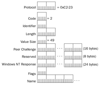
Figure 4-8: The MS-CHAP v2 Response message structure.
The following are the fields in the MS-CHAP v2 Response message:
- CodeFor an MS-CHAP v2 Response message, the value of the Code field is set to 2.
- IdentifierA 1-byte field that is set to the value of the Identifier field in the original CHAP Challenge message.
- LengthA 2-byte field that indicates the size of the MS-CHAP v2 Response message in bytes.
- Value SizeA 1-byte field that indicates the size of the CHAP Value field. For the MS-CHAP v2 Response message, the CHAP Value field consists of the Peer Challenge, Reserved, Windows NT Response, and Flags fields and is a fixed size of 49 bytes.
- Peer ChallengeA 16-byte field that contains the challenge string for theanswering peer as set by the calling peer.
- ReservedAn 8-byte field that should be set to 0.
- Windows NT ResponseA 24-byte field that contains the Windows NT–encoded response.
- FlagsA 1-byte field that is reserved for future use and should be set to 0.
- NameA variable-sized field that contains the name of the calling peer.
Capture 04-05 in the Captures folder on the companion CD-ROM contains an example of an MS-CHAP v2 authentication.
Like MS-CHAP, MS-CHAP v2 also allows the answering peer to indicate specific error conditions in the Message field of the CHAP Failure message. One of the errors is ERROR_PASSWD_EXPIRED. When the calling peer receives this error indication, it can submit an MS-CHAP v2 Change Password message to submit a new password for the account corresponding to the user name. For more information about the MS-CHAP v2 Change Password message, see RFC 2759.
EAP
EAP was designed as an extension to PPP to allow for more extensibility and flexibility in the implementation of authentication methods for PPP connections. For PAP, CHAP, MS-CHAP, and MS-CHAP v2, the authentication process is a fixed exchange of messages. With EAP, the authentication process can consist of an open-ended conversation, in which messages are sent by either PPP peer on an as-needed basis. In addition, unlike the PPP authentication protocols discussed so far in this chapter, EAP does not select a specific authentication method during phase 1 of the connection. Rather, the selection of a specific EAP authentication method, known as an EAP type, is done during phase 3 of the connection. EAP is described in RFC 2284.
When EAP is negotiated during phase 1, the LCP option data for the authentication protocol indicates EAP (0xC2-27). EAP messages use the PPP Protocol ID 0xC2-27.
The Windows Server 2003 family includes the EAP-MD5 CHAP, EAP-Transport LevelSecurity (TLS), and Protected EAP (PEAP) EAP types. Because EAP is architecturally designed to support multiple EAP types, additional types can be added by creating an EAP type dynamic-link library (DLL) file using the EAP Software Development Kit (SDK), which is part of the Windows Server Platform SDK, and installing the DLL file on the calling peer and the authenticating server. The authenticating server is the computer that actually performs the validation of the calling peer's credentials and is typically either the answering peer or a central authentication server, such as a Remote Authentication Dial-In User Service (RADIUS) server.
EAP defines four types of messages:
- An EAP-Request message is sent by the authentication server to request information from the calling peer. There can be multiple EAP-Request messages for an EAP authentication session.
- An EAP-Response message is sent by the calling peer to indicate information requested by the authentication server in an EAP-Request message.
- An EAP-Success message is sent by the authentication server when the calling peer has successfully responded to all of the EAP-Request messages for the EAP session.
- An EAP-Failure message is sent by the authentication server when the calling peer has not successfully responded to all of the EAP-Request messages for the EAP session.
Figure 4-9 shows the structure of EAP-Request and EAP-Response messages.
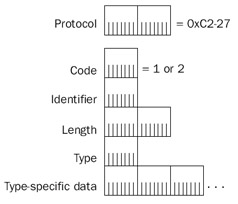
Figure 4-9: EAP-Request and EAP-Response message structure.
The following are the fields in an EAP-Request or EAP-Response message:
- CodeA 1-byte field that identifies the type of EAP message. For an EAP-Request message, the value of the Code field is set to 1. For an EAP-Response message, the value of the Code field is set to 2.
- IdentifierA 1-byte field that is used to match an EAP-Request message with an EAP-Response message.
- LengthA 2-byte field that indicates the size of the EAP message in bytes.
- TypeA 1-byte field that indicates the EAP type. For EAP-MD5 CHAP, the value of the Type field is 4.
- Type-Specific DataA variable-sized field that contains data for the specific EAP message. For example, in the EAP-Response/Identity message, the type-specific data is a string that identifies the calling PPP peer.
Table 4-3 lists EAP types.
|
Type Value |
Type |
Description |
|---|---|---|
|
1 |
Identity |
Used by the authenticating server to request the identity of the calling client (in the EAP-Request/Identity message) and used by the calling client to indicate its identity to the authenticating server (in the EAP-Response/Identity message). |
|
2 |
Notification |
Used by the authentication server to indicate a displayable message to the calling peer. |
|
3 |
Nak |
Used by a calling peer in a response message to indicate that the calling peer does not support the authentication type proposed by the authenticating server. The Nak message also includes a proposed authentication type that is supported by the calling peer. |
|
4 |
MD5 Challenge |
Used for the messages of the MD5-CHAP authentication method. |
|
13 |
EAP-TLS |
Used for the messages of the TLS authentication method. |
Figure 4-10 shows the structure of EAP-Success and EAP-Failure messages.
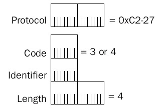
Figure 4-10: EAP-Success and EAP-Failure message structure.
The following are the fields in an EAP-Success and EAP-Failure message:
- CodeFor an EAP-Success message, the value of the Code field is set to 3. For an EAP-Failure message, the value of the Code field is set to 4.
- IdentifierSet to the value of the last EAP-Response message.
- LengthFor the EAP-Success and EAP-Failure messages, the Length field is set to 4.
EAP-MD5 CHAP
The EAP-MD5 CHAP type is the MD5-based CHAP authentication protocol performed using EAP messages, rather than its own messages. EAP-MD5 CHAP authentication consists of the following process:
- The authenticating server sends an EAP-Request/Identity message to the call-ing peer.
- The calling peer sends an EAP-Response/Identity message to the authenticat-ing server.
- The authenticating server sends an EAP-Request/MD5-Challenge message to the calling peer containing a challenge string and the name of the authenticating server.
- The calling peer sends an EAP-Response/MD5-Challenge message to the authenticating server containing the user's name and an MD5 hash of the CHAP session ID, the challenge string, and the user's password.
- The authenticating server calculates its own MD5 hash of the CHAP session ID, the challenge string, and the user's password and compares the result with the MD5 hash in the EAP-Response/MD5-Challenge message. If the two hashes are identical, the authenticating server sends an EAP-Success message. If not, the authenticating server sends an EAP-Failure message and the connection isterminated.
Figure 4-11 shows the structure of the EAP-Request/MD5-Challenge and EAP-Response/MD5-Challenge messages.
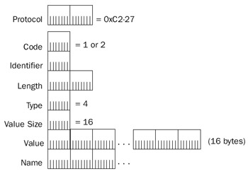
Figure 4-11: EAP-Request/MD5-Challenge and EAP-Response/MD5-Challenge message structure.
The following are the fields in the EAP-Request/MD5-Challenge and EAP-Response/MD5-Challenge messages:
- CodeA 1-byte field that identifies the type of EAP message. For an EAP-Request/MD5-Challenge message, the value of the Code field is set to 1. For an EAP-Response/MD5-Challenge message, the value of the Code field is set to 2.
- IdentifierA 1-byte field that is used to match an EAP-Request/MD5-Challenge message with an EAP-Response/MD5-Challenge message. This is the CHAP session ID for EAP-MD5 CHAP authentication.
- LengthA 2-byte field that indicates the size of the CHAP message in bytes.
- TypeA 1-byte field that indicates the EAP type. For EAP-MD5 Challenge, the value of the Type field is 4.
- Value SizeA 1-byte field that indicates the size of the Value field. Because the Value for MD5-Challenge is a 16-byte challenge string and the response is an MD5 hash (also 16 bytes long), the value of the Value Size field is set to 16 for both types of messages.
- ValueFor an EAP-Request/MD5-Challenge message, the Value field contains the challenge string of the authenticating server. For an EAP-Response/MD5-Challenge, the value contains an MD5 hash of the challenge string and the calling peer's user password.
- NameA variable-sized field that contains the name of either the authenticating server for the EAP-Request/MD5-Challenge message or the calling peer for the EAP-Response/MD5-Challenge message.
Capture 04-06 in the Captures folder on the companion CD-ROM contains an example of an EAP-MD5 CHAP authentication.
EAP-TLS
EAP-TLS is the use of TLS to provide authentication for the establishment of a PPP connection. TLS is described in RFC 2246 and EAP-TLS is described in RFC 2716. EAP-TLS provides mutual authentication (the calling PPP peer authenticates to the authenticating server and the authenticating server answers to the calling PPP peer), protected negotiation of the set of cryptographic services used for the connection, and mutual determination of encryption and signing key material. EAP-TLS uses certificates rather than passwords for authentication, resulting in a highly secure authentication method.
The details of EAP-TLS negotiation are beyond the scope of this book. For more details, see RFCs 2716 and 2246.
Callback and the Callback Control Protocol
After the authentication phase of the PPP connection process, CBCP negotiates the use of callback. If callback is negotiated, the answering PPP peer terminates the PPP connection, and then calls the original calling PPP peer at a specified phone number. CBCP messages use the PPP Protocol ID 0xC0-29 and have the same structure as LCP messages. However, only the first seven LCP message types are used, corresponding to LCP Codes 1 through 3. For the Callback-Request (Code set to 1), Callback-Response (Code set to 2), and Callback-Ack (Code set to 3) messages, the data portion of the CBCP message contains one or more CBCP options.
Table 4-4 lists the CBCP options used by Microsoft PPP peers.
|
Option Name |
Type |
Length |
Description |
|---|---|---|---|
|
No Callback |
1 |
2 |
Used to specify that callback is not used |
|
Callback to a User- Specified Number |
2 |
Variable |
Used to specify that the calling PPP peer determines the callback number |
|
Callback to an Administrator- Defined Number |
3 |
Variable |
Used to specify that the answering PPP peer determines the callback number |
|
Callback to Any of a List of Numbers |
4 |
Variable |
Used to specify that the answering PPP peer calls the calling PPP peer back at one of a list of phone numbers |
Network Control Protocols
After the callback phase of the PPP connection process, individual NCPs are used to negotiate the configuration of networking protocols, such as TCP/IP, and the additional PPP facilities of compression and encryption.
IPCP
IPCP is used to automatically configure TCP/IP configuration for a calling PPP peer. IPCP as used by Microsoft PPP peers is described in RFCs 1332 and 1877. RFC 1332 defines the original set of IPCP options and RFC 1877 defines an additional set of options to automatically configure the IP address of name servers such as Domain Name System (DNS) and Windows Internet Name Service (WINS) servers.
IPCP messages use the PPP Protocol ID 0x80-21 and have the same structure as LCP messages. However, only the first seven LCP message types are used, corresponding to LCP Codes 1 through 7. For the Configure-Request (Code set to 1), Configure-Ack (Code set to 2), Configure-Nak (Code set to 3), and Configure-Reject (Code set to 4) IPCP messages, the data portion of the IPCP message contains one or more IPCP options.
Table 4-5 lists the IPCP options defined in RFCs 1332 and 1877 that are used by Microsoft PPP peers.
|
Option Name |
Type |
Length |
Description |
|---|---|---|---|
|
IP Compression Protocol |
2 |
4 |
Negotiates the use of Van Jacobsen compression |
|
IP Address |
3 |
6 |
Used to assign an IP address to the point-to- point interface of the calling PPP peer |
|
Primary DNS Server Address |
129 |
6 |
Used to assign a primary DNS server to the point-to-point interface of the calling PPP peer |
|
Primary NBNS Server |
130 |
6 |
Used to assign a primary NetBIOS NameAddress Server (NBNS) server, a WINS server, to the point-to-point interface of the calling PPP peer |
|
Secondary DNS Server |
131 |
6 |
Used to assign a secondary DNS server to theAddress point-to-point interface of the calling PPP peer |
|
Secondary NBNS Server |
132 |
6 |
Used to assign a secondary NBNS server, aAddress WINS server, to the point-to-point interface of the calling PPP peer |
A typical TCP/IP configuration for a local area network (LAN) interface includes an IP address, a subnet mask, and a default gateway. A PPP interface configured with IPCP does not include a subnet mask or a default gateway. For computers running Windows XP or a member of the Windows Server 2003 family, the subnet mask of 255.255.255.255 is automatically configured. In addition, a new default route is added to the routing table. This new default route has the gateway and interface addresses set to the IP address of the PPP interface and a routing metric of 1. The routing metric of the existing default route is increased for the duration of the PPP connection. This behavior can be modified in the General tab of the Properties dialog box of the TCP/IP protocol for a dial-up or VPN connection by clearing the Use Default Gateway On Remote Network check box.
Although DNS server IP addresses are assigned, a DNS domain name is not. To automatically configure a DNS domain name, PPP calling peers running Windows XP or a member of the Windows Server 2003 family send a DHCPINFORM message on the PPP link after the PPP connection is established. If the answering peer supports the relaying of Dynamic Host Configuration Protocol (DHCP) messages, the DHCPINFORM message is relayed to a DHCP server and the response is relayed back to the PPP calling peer. Based on the DNS domain name DHCP option (Option 15) in the response, the PPP peerautomatically configures a DNS domain name on the point-to-point interface.
Compression Control Protocol
Compression Control Protocol (CCP), described in RFC 1962, allows PPP peers to negotiate the use of a data compression algorithm. CCP messages use the PPP Protocol 0x80-FD and have the same structure as LCP messages. However, only the first seven LCP message types are used, corresponding to LCP Codes 1 through 7. For the Configure-Request (Code set to 1), Configure-Ack (Code set to 2), Configure-Nak (Code set to 3), and Configure-Reject (Code set to 4) CCP messages, the data portion of the CCP message contains one or more CCP options. Table 4-6 lists these CCP options.
|
Option Name |
Type |
Length |
Description |
|---|---|---|---|
|
Organization Unique Identifier |
0 |
6 or larger |
Used to identify a proprietary compression protocol |
|
Microsoft Point-to-Point |
18 |
6 |
Used to indicate the use of MPPC, Microsoft Point-Compression (MPPC) to-Point Encryption (MPPE), and MPPE encryption options |
MPPE and MPPC
CCP option 18 for MPPC is used to negotiate the use of both MPPC and MPPE, as described in RFC 3078. The data for CCP option is a 4-byte (32-bit) Supported Bits field that contains bits to indicate the use of CCP and the use of MPPE and MPPE encryption options. Within the 32-bit Supported Bits field, the following bits are defined:
- The low-order bit enables (when set to 1) or disables (when set to 0) the use of MPPC.
- The fifth low-order bit (starting from 1) enables (when set to 1) or disables (when set to 0) the use of 40-bit encryption keys for MPPE that are derived from the LAN Manager encoding of the user's password. This bit is obsolete and its use should be rejected.
- The sixth low-order bit (starting from 1) enables (when set to 1) or disables (when set to 0) the use of 40-bit encryption keys for MPPE that are derived from the Windows NT encoding of the user's password.
- The seventh low-order bit (starting from 1) enables (when set to 1) or disables (when set to 0) the use of 128-bit encryption keys for MPPE that are derived from the Windows NT encoding of the user's password.
- The eighth low-order bit (starting from 1) enables (when set to 1) or disables (when set to 0) the use of 56-bit encryption keys that are derived from the Windows NT encoding of the user's password.
- The 25th low-order bit (starting from 1) enables (when set to 1) or disables (when set to 0) the use of stateless encryption mode, in which the MPPE encryption key is changed with every message sent or received.
When negotiating MPPC and MPPE, the PPP peers determine a common setting for MPPC (enabled or disabled), a common highest MPPE encryption strength (the use of 40-bit, 56-bit, or 128-bit encryption keys), and whether to use stateless MPPE.
MPPE is only possible if the authentication protocol used during the authentication phase is MS-CHAP, MS-CHAP v2, or EAP-TLS. Only these authentication methods provide mutually determined keying material that is used as the initial MPPE encryption key.
Both MPPC and MPPE use the same PPP Protocol ID, 0x00-FD. However, each PPP peer knows whether MPPC, MPPE, or both are being used for frames sent on the PPP connection. Therefore, for the following cases:
- If MPPC is used and MPPE is not, the PPP Protocol ID is 0x00-FD and the PPP payload is decompressed using the MPPC decompression algorithm.
- If MPPE is used and MPPC is not, the PPP Protocol ID is 0x00-FD and the PPP payload is decrypted using the MPPE decryption algorithm.
- If both MPPC and MPPE are used, the PPP payload is always compressedbefore it is encrypted. Therefore, the PPP Protocol ID 0x00-FD identifies an MPPE-encrypted payload. The payload is first decrypted using MPPE. The resulting MPPE payload consists of a PPP header with the PPP Protocol ID set to 0x00-FD and a payload compressed with MPPC. MPPC decompresses the payload. The resulting MPPC payload consists of a PPP header with the PPP Protocol ID set to 0x00-21 (assuming an IP datagram).
If the PPP payload is compressed with MPPC or encrypted with MPPE, the PPP payload is not parsed by Network Monitor. When using Network Monitor to troubleshoot PPP payloads after the PPP connection is created, disable compression and encryption.
Encryption Control Protocol
Encryption Control Protocol (ECP), described in RFC 1968, allows PPP peers to negotiate the use of a data encryption algorithm. ECP messages use the PPP Protocol IDs 0x80-53 or 0x80-55 and have the same structure as LCP messages. However, because Microsoft PPP peers only support the use of MPPE for encryption of PPP payloads, ECP is not supported or used. For more information, see RFC 1968.
Network Monitor Example
The following Network Monitor summary (Capture 04-07 in the Captures folder on the companion CD-ROM) is an example of a successful PPP connection using the MS-CHAP v2 authentication protocol:
1 7.060152 RECV RECV LCP Config Req
 Packet, Ident = 0x00, Length = 50
2 7.060152 SEND SEND LCP Config Req
 Packet, Ident = 0x00, Length = 58
3 7.060152 SEND SEND LCP Config Ack
 Packet, Ident = 0x00, Length = 50
4 7.130253 RECV RECV LCP Config Reject
 Packet, Ident = 0x00, Length = 8
5 7.130253 SEND SEND LCP Config Req
 Packet, Ident = 0x01, Length = 54
6 7.220383 RECV RECV LCP Config No Ack
 Packet, Ident = 0x01, Length = 9
7 7.220383 SEND SEND LCP Config Req
 Packet, Ident = 0x02, Length = 55
8 7.320527 RECV RECV LCP Config Ack
 Packet, Ident = 0x02, Length = 55
9 7.320527 SEND SEND PPPCHAP Challenge, ID =
 0x 0: Challenge
10 7.330541 RECV RECV LCP Ident Packet,
 Ident = 0x01, Length = 18
11 7.350570 RECV RECV LCP Ident Packet,
 Ident = 0x02, Length = 24
12 7.390628 RECV RECV PPPCHAP Challenge, ID =
 0x 0: Response, test
13 7.390628 SEND SEND PPPCHAP Challenge, ID =
 0x 0: Success
14 7.390628 SEND SEND CBCP Callback Request,
 Ident = 0x01
15 7.430685 RECV RECV CBCP Callback
 Response, Ident = 0x01
16 7.430685 SEND SEND CBCP Callback
 Acknowledgement, Ident = 0x01
17 7.440700 SEND SEND CCP Configuration
 Request, Ident = 0x04
18 7.440700 SEND SEND IPCP Configuration
 Request, Ident = 0x05
19 7.450714 RECV RECV CCP Configuration
 Request, Ident = 0x03
20 7.450714 SEND SEND CCP Configuration
 Acknowledgement, Ident = 0x03
21 7.470743 RECV RECV IPCP Configuration
 Request, Ident = 0x04
22 7.470743 SEND SEND IPCP Configuration
 Reject, Ident = 0x04
23 7.480757 RECV RECV CCP Configuration
 Acknowledgement, Ident = 0x04
24 7.490772 RECV RECV IPCP Configuration
 Acknowledgement, Ident = 0x05
25 7.510800 RECV RECV IPCP Configuration
 Request, Ident = 0x05
26 7.510800 SEND SEND IPCP Configuration No
 Acknowledgement, Ident = 0x05
27 7.540844 RECV RECV IPCP Configuration
 Request, Ident = 0x06
28 7.540844 SEND SEND IPCP Configuration
 Acknowledgement, Ident = 0x06
In this example, the following frames show the four phases of the PPP connection:
- Frames 1 through 8 and frames 10 and 11 are for phase 1, the LCP negotiation.
- Frames 9, 12, and 13 are for phase 2, authentication.
- Frames 14 through 16 are for phase 3, callback.
- Frames 16, 19, 20, and 23 are for CCP negotiation (in phase 4). Frames 18, 21, 22, and 24 through 28 are for IPCP negotiation (in phase 4).
PPP over Ethernet
PPP over Ethernet (PPPoE) is a method of encapsulating PPP frames so that they can be sent over an Ethernet network. PPPoE was created so that Internet service providers (ISPs) that deploy a broadband Internet access technology in a bridged Ethernet topology, such as cable modems or Digital Subscriber Line (DSL), can use the per-user authentication and connection identification facilities of PPP to identify individual customer connections for accounting and billing purposes. PPPoE is described in RFC 2516.
PPPoE connections have the following two phases:
- A discovery phase in which a client computer uses PPPoE frames to discover the presence of an access concentrator (AC), a device that terminates the cable modem or DSL connection and provides access to the Internet, and to determine a PPPoE session ID
- A PPP session phase, in which a PPP connection is established and used for data transfer in the same way as a dial-up or VPN-based PPP connection
Figure 4-12 shows a PPPoE frame.
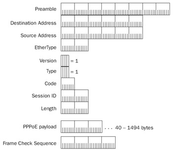
Figure 4-12: The structure of a PPPoE frame.
The following are the fields in the PPPoE frame:
- VersionA 4-bit field that is set to the value of 1.
- TypeA 4-bit field that is set to the value of 1.
- CodeA 1-byte field that is used to identify the type of PPPoE message. There are defined values for the PPPoE frames exchanged during the discovery phase. For PPP frames, the Code field is set to 0.
- Session_IDA 2-byte field that identifies the PPPoE session ID. This field is set to 0 until a session ID is negotiated with the AC during the discovery phase of the PPPoE connection.
- LengthA 2-byte field that is used to indicate the size in bytes of the PPPoE payload.
- PPPoE PayloadA variable-sized payload that can contain either one or more PPPoE tags for PPPoE frames sent during the discovery phase or PPP frames for the PPP session phase. PPPoE tags are information elements in TLV format. Typical PPPoE tags used during the discovery phase are Service-Name (the name of the ISP or service offered by the AC) and AC-Name (the name of the AC). For a complete list of PPPoE tags and their structure, see RFC 2516. The EtherType value in the Ethernet II header for PPPoE frames is set to 0x88-63 for PPPoE discovery frames and 0x88-64 for PPP session frames. For more information about the Ethernet II header, see Chapter 1, "Local Area Network (LAN) Technologies."
PPPoE Discovery Stage
The PPPoE discovery process consists of the following four PPPoE frames:
- The PPPoE Active Discovery Initiation (PADI) frame is sent by the PPPoE client to the Ethernet broadcast address (0xFF-FF-FF-FF-FF-FF). Within the Ethernet payload, the Code field is set to 9, the Session ID is set to 0, and there is a single Service-Name PPPoE tag, as well as other tags as needed. If the network connection in the Network Connections folder corresponding to the broadband Internet adapter has been configured with a service name, that service name is sent. Otherwise, the PADI frame is sent with a null service name.
- The PPPoE Active Discovery Offer (PADO) frame is sent by the AC to the unicast MAC address of the PPPoE client. Within the Ethernet payload, the Code field is set to 7, the Session ID is set to 0, there are the AC-Name and Service-Name tags, and other tags as needed. If the network connection in the Network Connections folder corresponding to the broadband Internet adapter has not been configured with a service name, it is automatically set to the value of the Service-Name tag in the PADO frame.
- The PPPoE Active Discovery Request (PADR) frame is sent by the PPPoE client to the unicast MAC address of the AC. Within the Ethernet payload, the Code field is set to 25, the Session ID is set to 0, and there is a Service-Name tag and other tags as needed.
- The PPPoE Active Discovery Session-confirmation (PADS) frame is sent bythe AC to the unicast MAC address of the PPPoE client. Within the Ethernet payload, the Code field is set to 101, the Session ID field is set to the session ID for the PPP session of the PPPoE client, and there is a Service-Name tag, as well as other tags as needed.
To terminate the PPPoE session, either the PPPoE client or the AC can send a PPPoE Active Discovery Terminate (PADT) frame, which contains the Code field set to 167 and the session ID set to the session being terminated.
PPPoE Session Stage
After the PPPoE discovery process is complete, a PPP connection is negotiated and network protocol data such as IP datagrams are sent over the PPPoE connection. Figure 4-13 shows a PPPoE frame that contains a PPP frame.
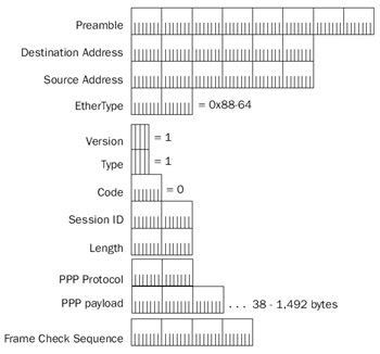
Figure 4-13: The structure of a PPPoE frame that contains a PPP frame.
Because of the additional PPPoE overhead, the maximum size of PPP frames that can be sent over a PPPoE connection is 1494 bytes.
Summary
PPP is used for encapsulation, link negotiation, and network protocol negotiation for network protocol packets that are sent over a point-to-point link. The PPP connection process has four phases: link negotiation, authentication, callback negotiation, and network protocol negotiation. During link negotiation, each PPP peer determines how it will send PPP frames. During authentication, PPP authentication protocols such as CHAP, MS-CHAP, and EAP are used to verify the credentials of the calling or answering PPP peer. During callback negotiation, the calling and answering PPP peers determine whether the answering PPP peer will call the calling peer back and at which phone number. During network protocol negotiation, NCPs such as IPCP, CCP, and ECP are used to determine the use and configuration of TCP/IP, compression, and encryption.
PPPoE is a method of encapsulating PPP frames so that they can be sent over an Ethernet link. A PPPoE connection consists of two phases: a PPPoE discovery phase and a PPPoE session phase. After a PPPoE connection is negotiated during the discovery phase, PPP is used to negotiate a connection and send network protocol frames during the PPPoE session phase.
Part I - The Network Interface Layer
- Local Area Network (LAN) Technologies
- Wide Area Network (WAN) Technologies
- Address Resolution Protocol (ARP)
- Point-to-Point Protocol (PPP)
Part II - Internet Layer Protocols
- Internet Protocol (IP) Basics
- Internet Protocol (IP) Addressing
- Internet Protocol (IP) Routing
- Internet Control Message Protocol (ICMP)
- Internet Group Management Protocol (IGMP)
- Internet Protocol Version 6 (IPv6)
Part III - Transport Layer Protocols
- User Datagram Protocol
- Transmission Control Protocol (TCP) Basics
- Transmission Control Protocol (TCP) Connections
- Transmission Control Protocol (TCP) Data Flow
- Transmission Control Protocol (TCP) Retransmission and Time-Out
Part IV - Application Layer Protocols and Services
- Dynamic Host Configuration Protocol (DHCP) Server Service
- Domain Name System (DNS)
- Windows Internet Name Service (WINS)
- File and Printer Sharing
- RADIUS and Internet Authentication Service
- Internet Information Services (IIS) and the Internet Protocols
- Internet Protocol Security (IPSec)
- Virtual Private Networks (VPNs)
EAN: N/A
Pages: 216
