Wide Area Network (WAN) Technologies
Overview
To successfully troubleshoot TCP/IP problems on a wide area network (WAN), it isimportant to understand how IP datagrams and Address Resolution Protocol (ARP) messages are encapsulated by a computer running a member of the Microsoft Windows Server 2003 family or Windows XP that uses a WAN technology such as T-carrier, Public Switched Telephone Network (PSTN), Integrated Services Digital Network (ISDN), X.25, frame relay, or Asynchronous Transfer Mode (ATM). It is also important to understand WAN technology encapsulations to interpret the WAN encapsulation portions of a frame when using Microsoft Network Monitor or other types of WAN frame capture programs orfacilities.
WAN Encapsulations
As discussed in Chapter 1, "Local Area Network (LAN) Technologies," IP datagrams are an Open Systems Interconnection (OSI) Network Layer entity that requires a Data Link Layer encapsulation before being sent on a physical medium. For WAN technologies, the Data Link Layer encapsulation provides the following services:
- DelimitationFrames at the Data Link Layer must be distinguished from each other, and the frame's payload must be distinguished from the Data Link Layer header and trailer.
- Protocol identificationOn a multiprotocol WAN link, protocols such as TCP/IP, Internetwork Packet Exchange (IPX), or AppleTalk must be distinguished from each other.
- AddressingFor WAN technologies that support multiple possible destinations using the same physical link, the destination must be identified.
- Bit-level integrity checkA checksum provides a bit-level integrity check between either the peer nodes on the link or forwarding nodes on a packet-switching network.
This chapter discusses WAN technologies and their encapsulations for IP datagrams and ARP messages. WAN encapsulations are divided into two categories based on the types of IP networks of the WAN link:
- Point-to-point links support an IP network segment with a maximum of two nodes. These links include analog phone lines, ISDN lines, Digital Subscriber Line (DSL) lines, and T-carrier links such as T-1, T-3, Fractional T-1, E-1, and E-3. Point-to-point links do not require Data Link Layer addressing.
- Non-broadcast multiple access (NBMA) links support an IP network segment with more than two nodes; however, there is no facility to broadcast a single IP datagram to multiple locations. NBMA links include packet-switching WAN technologies such as X.25, frame relay, and ATM. NBMA links require Data Link Layer addressing.
Point to Point Encapsulation
The two most prominent industry standard encapsulations for sending IP datagrams over a point-to-point link are Serial Line Internet Protocol (SLIP) and Point-to-Point Protocol (PPP).
SLIP
As RFC 1055 describes, SLIP is a very simple packet-framing protocol that offers only frame delimitation services. SLIP does not provide protocol identification or bit-level integrity verification services. SLIP was designed to be easy to implement for links that did not require these types of services.
| More Info |
SLIP is described in RFC 1055, which can be found in the Rfc folder on the companion CD-ROM. |
To delimit IP datagrams, SLIP uses a special character called the END character (0xC0), which is placed at the beginning and end of each IP datagram. Successive IP datagrams have two END characters between them: one to mark the end of one datagram and one to mark the beginning of another.
The END character presents a problem because if it occurs within the IP datagram and is sent unmodified, the receiving node interprets the END character as the marker for the end of the IP datagram. If this happens, the originally sent IP datagram is truncated and is eventually discarded because of failed checksums in the IP header and upper layer protocol headers. Figure 2-1 shows a SLIP-encapsulated IP datagram.
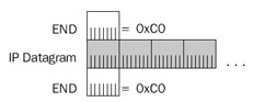
Figure 2-1: SLIP encapsulation, showing the simple frame delimitation services for an IP datagram.
To prevent the occurrence of the END character within the IP datagram, SLIP uses a technique called character stuffing. The END character is escaped, or replaced, with a sequence beginning with another special character called the ESC (0xDB) character. The SLIP ESC character has no relation to the American Standard Code for Information Interchange (ASCII) ESC character.
If the END character occurs within the original IP datagram, it is replaced with thesequence 0xDB-DC. To prevent the misinterpretation of the ESC character by the receiving node, if the ESC (0xDB) character occurs within the original IP datagram, it is replaced with the sequence 0xDB-DD. Therefore:
- END characters can occur only at the beginning and end of the SLIP frame.
- On the sending node, SLIP replaces the END character within the IP datagram with the sequence 0xDB-DC. On the receiving node, SLIP translates the 0xDB-DC sequence back to 0xC0.
- On the sending node, SLIP replaces the ESC character within the IP datagram with the sequence 0xDB-DD. On the receiving node, the 0xDB-DD sequence is translated back to 0xDB. If the IP datagram contains the sequence 0xDB-DC, the escaping of the ESC character turns this sequence into 0xDB-DD-DC to prevent the receiver from misinterpreting the 0xDB-DC sequence as 0xC0.
Figure 2-2 shows SLIP character stuffing.
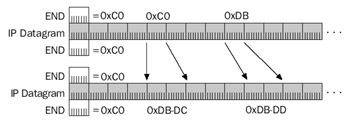
Figure 2-2: SLIP character stuffing, showing the escaping of the END and ESC characters within an IP datagram.
As RFC 1055 describes, the maximum size of an IP datagram over a SLIP connection is 1006 bytes—the size imposed by Berkeley UNIX drivers that existed when the RFC was written. Most systems adhere to the industry standard maximum size of 1006 bytes. However, some systems, such as those running the Windows Server 2003 family orWindows XP, allow a maximum packet size of 1500 bytes over a SLIP connection to prevent fragmentation of IP datagrams when SLIP links are used in conjunction with Ethernet network segments.
Although SLIP does not provide for the negotiation of compression methods during the connection setup, SLIP does support a compression scheme known as Compressed SLIP (C-SLIP).
| More Info |
RFC 1144 describes C-SLIP and how it is used to compress IP and TCP headers to a 3- to 5-byte header on the SLIP link. This RFC can be found in the Rfc folder on the companion CD-ROM. |
Dial-up network connections for the Windows Server 2003 family and Windows XP use SLIP and C-SLIP to create SLIP-based remote access connections to a network access server. The incoming connections feature of the Network Connections folder and the Windows Server 2003 family Routing and Remote Access service does not support SLIP or C-SLIP.
PPP
PPP is a standardized point-to-point network encapsulation method that addresses the shortcomings of SLIP and provides Data Link Layer functionality comparable to LAN encapsulations. PPP provides frame delimitation, protocol identification, and bit-level integrity services.
| More Info |
PPP is described in RFC 1661, which can be found in the Rfc folder on the companion CD-ROM. |
RFC 1661 describes PPP as a suite of protocols that provide the following:
- A Data Link Layer encapsulation method that supports multiple protocolssimultaneously on the same link.
- A protocol for negotiating the Data Link Layer characteristics of the point-to-point connection named the Link Control Protocol (LCP).
- A series of protocols for negotiating the Network Layer properties of Network Layer protocols over the point-to-point connection named Network Control Protocols (NCPs). For example, RFCs 1332 and 1877 describe the NCP for IP called Internet Protocol Control Protocol (IPCP). IPCP is used to negotiate an IP address, the addresses of name servers, and the use of the Van Jacobsen TCP compression protocol.
This chapter discusses only the Data Link Layer encapsulation. Chapter 4, "Point-to-Point Protocol (PPP)," describes LCP and the NCPs needed for IP connectivity.
PPP encapsulation and framing is based on the International Organization for Standardization (ISO) High-Level Data Link Control (HDLC) protocol. HDLC was derived from the Synchronous Data Link Control (SDLC) protocol developed by IBM for the Systems Network Architecture (SNA) protocol suite. HDLC encapsulation for PPP frames is shown in Figure 2-3.
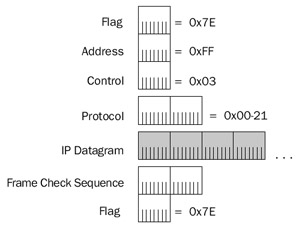
Figure 2-3: PPP encapsulation using HDLC framing for an IP datagram.
| More Info |
HDLC encapsulation for PPP frames is described in RFC 1662, which can be found in the Rfc folder on the companion CD-ROM. |
The fields in the PPP header and trailer are defined as follows:
- FlagA 1-byte field set to 0x7E (bit sequence 01111110) that indicates the start and end of a PPP frame. Unlike SLIP, a single FLAG character is used between back-to-back PPP frames.
- AddressA 1-byte field that is a by-product of HDLC. In HDLC environments, the Address field is used as a destination address on a multipoint network. PPP links are point-to-point and the destination node is always the other node on the point-to-point link. Therefore, the Address field for PPP encapsulation is set to 0xFF—the broadcast address.
- ControlA 1-byte field that is also an HDLC by-product. In HDLC environments, the Control field is used to implement sequencing and acknowledgments to provide Data Link Layer reliability services. For session-based traffic, the Control field is more than 1 byte long. For datagram traffic, the Control field is 1 byte long and set to 0x03 to indicate an unnumbered information (UI) frame. Because PPP does not provide reliable Data Link Layer services, PPP frames are always UI frames. Therefore, PPP frames always use a 1-byte Control field set to 0x03.
- ProtocolA 2-byte field used to identify the upper layer protocol of the PPP payload. For example, 0x00-21 indicates an IP datagram, 0x00-29 indicates an AppleTalk datagram, and 0x00-2B indicates an IPX datagram.
For the current list of PPP protocol numbers, see http://www.iana.org/assignments/ppp-numbers.
- Frame Check Sequence (FCS)A 2-byte field used to provide bit-level integrity services for the PPP frame. The sender calculates the FCS, which is then placed in the FCS field. The receiver performs the same FCS calculation and compares its result with the result stored in this field. If the two FCS values match, the PPP frame is considered valid and is processed further. If the two FCS values do not match, the PPP frame is silently discarded.
The HDLC encapsulation for PPP frames is also used for Asymmetric Digital Subscriber Line (ADSL) broadband Internet connections.
Figure 2-4 shows a typical PPP framing for an IP datagram when using Address and Control field suppression and Protocol field compression.
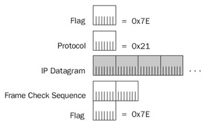
Figure 2-4: Typical PPP encapsulation for an IP datagram.
This abbreviated form of PPP framing is a result of the following:
- Because the Address field is irrelevant for point-to-point links, in most cases the PPP peers agree during LCP negotiation to not include the Address field. This is done through the Address and Control Field Compression LCP option.
- Because the Control is always set to 0x03 and provides no other service, in most cases the PPP peers agree during LCP negotiation to not include theControl field. This, too, is done through the Address and Control FieldCompression LCP option.
- Because the high-order byte of the PPP Protocol field for Network Layer protocols such as IP, AppleTalk, and IPX is always set to 0x00, in most cases the PPP peers agree during LCP negotiation to use a 1-byte Control field. This is done through the Protocol Compression LCP option.
Note For the Windows Server 2003 family, PPP frames captured with the Network Monitor do not display the HDLC structure, as shown in Figures 2-3 and 2-4. PPP control frames contain simulated source and destination media access control (MAC) addresses and only the PPP Protocol field. PPP data frames contain a simulated Ethernet II header.
PPP on Asynchronous Links
As in SLIP, PPP on asynchronous links such as analog phone lines uses character stuffing to prevent the occurrence of the FLAG character within the PPP payload. The FLAG character is escaped, or replaced, with a sequence beginning with another special character called the ESC (0x7D) character. The PPP ESC character has no relation to the ASCII or SLIP ESC character.
If the FLAG character occurs within the original IP datagram, it is replaced with thesequence 0x7D-5E. To prevent the misinterpretation of the ESC character by the receiving node, if the ESC (0x7D) character occurs within the original IP datagram, it is replaced with the sequence 0x7D-5D. Therefore:
- FLAG characters can occur only at the beginning and end of the PPP frame.
- On the sending node, PPP replaces the FLAG character within the IP datagram with the sequence 0x7D-5E. On the receiving node, the 0x7D-5E sequence is translated back to 0x7E.
- On the sending node, PPP replaces the ESC character within the PPP frame with the sequence 0x7D-5D. On the receiving node, the 0x7D-5D sequence is translated back to 0x7D. If the IP datagram contains the sequence 0x7D-5E, the escaping of the ESC character turns this sequence into 0x7D-5D-5E to prevent the receiver from misinterpreting the 0x7D-5E sequence as 0x7E.
Additionally, character stuffing is used to stuff characters with values less than 0x20 (32 in decimal notation) to prevent these characters from being misinterpreted as control characters when software flow control is used over asynchronous links. The escape sequence for these characters is 0x7D-x, where x is the original character with the fifth bit set to 1. The fifth bit is defined as the third bit from the high-order bit using the bit position designation of 7-6-5-4-3-2-1-0. Therefore, the character 0x11 (bit sequence 0-0-0-1-0-0-0-1) would be escaped to the sequence 0x7D-31 (bit sequence 0-0-1-1-0-0-0-1).
The use of character stuffing for characters less than 0x20 is negotiated using the Asynchronous Control Character Map (ACCM) LCP option. This LCP option uses a 32-bit bitmap to indicate exactly which character values need to be escaped.
| More Info |
For more information on the ACCM LCP option, see RFCs 1661 and 1662. These can be found in the Rfc folder on the companion CD-ROM. |
PPP on Synchronous Links
Character stuffing is an inefficient method of escaping the FLAG character. If the PPP payload consists of a stream of 0x7E characters, character stuffing roughly doubles the size of the PPP frame as it is sent on the medium. For asynchronous, byte-boundary media such as analog phone lines, character stuffing is the only alternative.
On synchronous links such as T-carrier, ISDN, and Synchronous Optical Network (SONET), a technique called bit stuffing is used to mark the location of the FLAG character. Recall that the FLAG character is 0x7E, or the bit sequence 01111110. With bit stuffing, the only time six 1 bits in a row are allowed is for the FLAG character as it is used to mark the start and end of a PPP frame. Throughout the rest of the PPP frame, if there are five 1 bits in a row, a 0 bit is inserted into the bit stream by the synchronous link hardware. Therefore, the bit sequence 111110 is stuffed to produce 1111100 and the bit sequence 111111 is stuffed to become 1111101. Therefore, six 1 bits in a row cannot occur except for the FLAG character when it is used to mark the start and end of a PPP frame. If the FLAG character does occur within the PPP frame, it is bit stuffed to produce the bit sequence 011111010. Bit stuffing is much more efficient than character stuffing. If stuffed, a single byte becomes 9 bits, not 16 bits, as is the case with character stuffing. With synchronous links and bit stuffing, data sent no longer falls along bit boundaries. A single byte sent can be encoded as either 8 or 9 bits, depending on the presence of a 11111 bit sequence within the byte.
PPP Maximum Receive Unit
The maximum-sized PPP frame, the maximum transmission unit (MTU) for a PPP link, is known as the Maximum Receive Unit (MRU). The default value for the PPP MRU is 1500 bytes. The MRU for a PPP connection can be negotiated to a lower or higher value using the Maximum Receive Unit LCP option. If an MRU is negotiated to a value lower than 1500 bytes, a 1500-byte MRU must still be supported in case the link has to be resynchronized.
PPP Multilink Protocol
The PPP Multilink Protocol (MP) is an extension to PPP that allows you to bundleor aggregate the bandwidth of multiple physical connections. It is supported by theWindows Server 2003 family and Windows XP Network Connections and theWindows Server 2003 family Routing and Remote Access service. MP takes multiple physical connections and makes them appear as a single logical link. For example, with MP, two analog phone lines operating at 28.8 Kbps appear as a single connectionoperating at 57.6 Kbps. Another example is the aggregation of multiple channels of an ISDNBasic Rate Interface (BRI) or Primary Rate Interface (PRI) line. In the case of a BRI line, MP makes the two 64-Kbps BRI B-channels appear as a single connection operating at 128 Kbps.
| More Info |
MP is described in RFC 1991, which can be found in the Rfc folder on the companion CD-ROM. |
MP is an extra layer of encapsulation that operates within a PPP payload. To identify an MP packet, the PPP Protocol field is set to 0x00-3D. The payload of an MP packet is a PPP frame or the fragment of a PPP frame. If the size of the PPP payload that would be sent on a single-link PPP connection, plus the additional MP header, is greater than the MRU for the specific physical link over which the MP packet is sent, MP fragments the PPP payload.
MP fragmentation divides the PPP payload along boundaries that will fit within the link's MRU. The fragments are sent in sequence using an incrementing sequence number, and flags are used to indicate the first and last fragments of an original PPP payload. A lost MP fragment causes the entire original PPP payload to be silently discarded.
MP encapsulation has two different forms: the long sequence number format (shown in Figure 2-5) and the short sequence number format. The long sequence number format adds 4 bytes of overhead to the PPP payload.
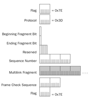
Figure 2-5: The Multilink Protocol header, using the long sequence number format.
The fields in the MP long sequence number format header are defined as follows:
- Beginning Fragment BitSet to 1 on the first fragment of a PPP payload and to 0 on all other PPP payload fragments.
- Ending Fragment BitSet to 1 on the last fragment of a PPP payload and to 0 on all other PPP payload fragments. If a PPP payload is not fragmented, both the Beginning Fragment Bit and Ending Fragment Bit are set to 1.
- ReservedSet to 0.
- Sequence NumberSet to an incrementally increasing number for each MP payload sent. For the long sequence number format, the Sequence Number field is 3 bytes long. The Sequence Number field is used to number successive PPP payloads that would normally be sent over a single-link PPP connection, and is used by MP to preserve the packet sequence as sent by the PPP peer. Additionally, the Sequence Number field is used to number individual fragments of a PPP payload so that the receiving node can detect a fragment loss.
Figure 2-6 shows the short sequence number format, which adds 2 bytes of overhead to the PPP payload.
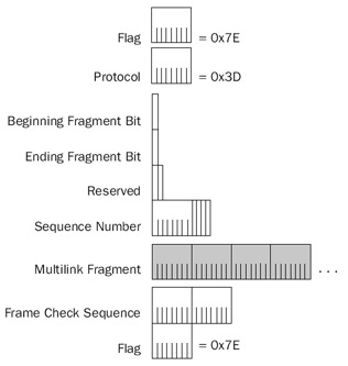
Figure 2-6: The Multilink Protocol header, using the short sequence number format.
The short sequence format has only 2 reserved bits, and its Sequence Number field is only 12 bits long. The long sequence number format is used by default unless the Short Sequence Number Header Format LCP option is used during the LCP negotiation.
X 25
In the 1970s, a standard set of protocols known as X.25 was created to provide users with a standard way to send packetized data across a packet-switched public data network (PSPDN). Until X.25, PSPDNs and their interfaces were proprietary and completelyincompatible. Changing PSPDN vendors meant purchasing new Public Data Network (PDN) interfacing equipment. X.25 is an international standard, as specified by theInternational Telecommunications Union-Telecommunication sector (ITU-T).
X.25 was developed during a time when the telecommunication infrastructure was largely based on noisy copper cabling. A typical use for PSPDNs at that time was the communication of a dumb terminal with a mainframe computer. Errors in transmission because of noisy cabling could not be recovered by dumb terminal equipment. Therefore, X.25 was designed to provide a reliable data transfer service—an unusual feature for a Data Link Layer protocol. All data sent to the PSPDN using X.25 was reliably received and forwarded to the desired endpoint. The reliable service of X.25 typically is not needed for the communication of more intelligent endpoints using protocol suites such as TCP/IP. However, X.25 is still used as a WAN technology over which to send TCP/IP data because of its international availability.
As Figure 2-7 shows, X.25 defines the interface between data terminal equipment (DTE) and data circuit-terminating equipment (DCE). A DTE can be a terminal that does not implement the complete X.25 functionality; as such, it is known as a nonpacket mode DTE. A nonpacket mode DTE is connected to a DCE through a translation device called a packet assembler/disassembler (PAD). X.25 does not attempt to define the nature of the DCE-to-DCE communication within the PSPDN. These details are left to the X.25 vendor.
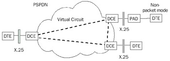
Figure 2-7: The X.25 WAN service, showing DTE, DCE, PAD, and the X.25 interface tothe PSPDN.
End-to-end communication between DTEs is accomplished through a bidirectional and full-duplex logical connection called a virtual circuit. Virtual circuits permit communication between DTEs without the use of dedicated circuits. Data is sent as it is produced, using the bandwidth of the PDN infrastructure more efficiently. X.25 can support permanent virtual circuits (PVCs) or switched virtual circuits (SVCs). A PVC is a path through a packet-switching network that is statically programmed into the switches. An SVC is a path through a packet-switching network that is negotiated using a signaling protocol each time a connection is initiated.
Once a virtual circuit is established, a DTE sends a packet to the other end of a virtual circuit using an X.25 virtual-circuit identifier called the Logical Channel Number (LCN). The DCE uses the LCN to forward the packet within the PDN to the appropriate destination DCE.
X.25 encompasses the Physical, Data Link, and Network Layers of the OSI model.
- Physical LayerX.25 can use a variety of interface standards such as X.21bis (roughly equivalent to EIA/TIA232C [formerly RS-232-C]) or V.35.
- Data Link LayerX.25 at the Data Link Layer uses a framing called Link Access Procedure-Balanced (LAPB), another variant of the HDLC protocol.
- Network LayerX.25 at the Network Layer uses a framing called Packet Layer Protocol (PLP). For X.25 SVCs, X.25 call setup packets contain a connection establishment address known as an X.121 address, also referred to as an International Data Number (IDN). X.121 addresses have a variable length (up to 14 decimal digits). Once the SVC is created, the LCN is used for data transfer. User data transfer is performed reliably between endpoints using flow control, sequencing, and acknowledgments.
Although X.25 is defined at the Physical, Data Link, and Network Layers of the OSI model, relative to sending IP datagrams, X.25 is a Data Link and Physical Layer technology.
Typical packet sizes for X.25 PSPDNs are 128, 256, or 512 bytes. User information, such as IP datagrams that are beyond the packet size of the X.25 PSPDN, are segmented by X.25 and reliably reassembled.
X 25 Encapsulation
X.25 encapsulation can take two different forms:
- If IP datagrams are the only type of data being sent across the virtual circuit, IP traffic is identified by setting the 1-byte Network Layer Protocol Identifier (NLPID) to 0xCC in the first octet in the Call User Data (CUD) field of the X.25 Call Request packet. IP datagrams are encapsulated with the X.25 PLP and LAPB headers.
- If IP datagrams are one of many types of data being sent across the virtual circuit (a multiprotocol link), the NLPID in the CUD field of the X.25 Call Request packet is set to 0x00 to indicate null encapsulation. IP datagrams are encapsulated with the NLPID header set to 0xCC and the X.25 PLP and LAPB headers.
More Info X.25 encapsulation of IP datagrams is described in RFC 1356, which can be found in the Rfc folder on the companion CD-ROM.
Figure 2-8 shows the X.25 encapsulation for IP datagrams on a multiprotocol link.
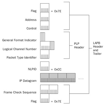
Figure 2-8: X.25 encapsulation of IP datagrams for a multiprotocol link.
NLPID
For multiprotocol virtual circuits, the 1-byte NLPID field is present and set to 0xCC to indicate an IP datagram. For a single protocol virtual circuit, the NLPID field is not present. If the IP datagram is fragmented, the NLPID is fragmented along with the IP datagram.
PLP Header
The fields in the X.25 PLP header are defined as follows:
- General Format Indicator (GFI)A 4-bit field that identifies the PLP payload as a user data or an X.25 message, the packet numbering scheme (modulo 8 or modulo 128), and whether delivery confirmation with the endpoint is required.
- Logical Channel Number (LCN)A 12-bit field that identifies the virtual circuit over which the X.25 packet is to travel. The LCN is only locally significant between the DTE and DCE. When an X.25 connection is negotiated, an X.25 LCN is assigned so that the originating node can multiplex data to the proper destination. Up to 4095 virtual circuits can be identified (LCN = 0 is used for X.25 signaling). The first 4 bits of the LCN were originally defined for use as a Logical Group Number (LGN). The LGN was intended for use as a method of bundling multiple logical X.25 channels together for X.25 virtual circuit routing, but it was never used. However, the concept of having a two-level hierarchy for virtual circuit identification is used for ATM.
- Packet Type IdentifierFor X.25 protocol messages, the 1-byte Packet Type Identifier field identifies the type of X.25 message. When user data is being sent, the Packet Type Identifier field is used to provide sequencing, acknowledgments, and X.25 fragmentation.
RFC 1356 sets the IP MTU for X.25 networks at 1600 bytes. However, most X.25 networks support only X.25 packet sizes of 128, 256, or 512 bytes. To accommodate the sending of a 1600-byte IP datagram over an X.25 network, X.25 fragments the IP datagram along boundaries that will fit on the X.25 network. A bit within the PTI field called the M-bit is used for fragment delimitation. Similar to the More Fragments flag in the IP header, the M-bit in the X.25 PLP header is set to 1 if more fragments follow, and set to 0 for the last fragment. Unlike IP fragmentation, X.25 fragmentation recovers from lost fragments.
LAPB Header and Trailer
The following fields are present in the LAPB header and trailer:
- FlagAs in PPP frames, the 1-byte Flag field is set to 0x7E to mark the beginning and end of the X.25 frame. Bit stuffing is used on synchronous links, and character stuffing is used on asynchronous links to prevent the occurrence of the FLAG character within the X.25 frame.
- AddressA 1-byte field used to specify X.25 commands and responses.
- ControlA 1-byte field that provides further qualifications of command and response frames, and also indicates the frame format and function. For X.25 protocol messages, the Control field provides sending and receiving sequence numbers.
- Frame Check Sequence (FCS)A 2-byte cyclical redundancy check (CRC) used to check for errors in the LAPB frame.
Frame Relay
When packet-switching networks were first introduced, they were based on existing analog copper lines that experienced a high number of errors. X.25 was designed to compensate for these errors and provide connection-oriented reliable data transfer. In these days of high-grade digital fiber-optic lines, there is no need for the overhead associated with X.25. Frame relay is a packet-switched technology similar to X.25, but without the added framing and processing overhead to provide guaranteed data transfer. Unlike X.25, frame relay does not provide link-to-link reliability. If a frame in the frame relay network is corrupted in any way, it is silently discarded. Upper layer communication protocols such as TCP must detect and recover discarded frames.
A key advantage frame relay has over private-line facilities, such as T-Carrier, is that frame relay customers can be charged based on the amount of data transferred, instead of the distance between the endpoints. It is common, however, for the frame relay vendor to charge a fixed monthly cost. In either case frame relay is distance-insensitive. A local connection, such as a T-1 line, to the frame relay vendor's network is required. Frame relay allows widely separated sites to exchange data without incurring long-haul telecommunications costs.
Frame relay is a packet-switching technology defined in terms of a standardized interface between user devices (typically routers) and the switching equipment in the vendor's network (frame relay switches).
Frame relay is similar to X.25 in the following ways:
- A packet-switching technology designed to send variable-sized packets.
- Designed for the transfer of LAN traffic (computer communication protocols such as TCP/IP).
- Provides a mechanism for multiplexing multiple logical connections (virtual circuits) over a single physical link.
However, frame relay differs from X.25 in the following ways:
- Frame relay is an unreliable data transfer service. Frame relay switches silently discard frames lost as a result of congestion or corruption.
- Frame relay provides no flow control. However, frame relay does provide for basic congestion notification that can be used to notify upper layer protocols to implement their own flow control.
Typical frame relay service providers currently only offer PVCs. The frame relayservice provider establishes the PVC when the service is ordered. A new standard foran SVC version of frame relay uses the ISDN signaling protocol as the mechanismfor establishing the virtual circuit. This new standard is not widely used in production networks.
Frame relay speeds range from 56 Kbps to 1.544 Mbps. The required throughput for a given link determines the committed information rate (CIR). The CIR is the throughput guaranteed by the frame relay service provider. Most frame relay service providers allow a customer to transmit bursts above the CIR for short periods of time. Depending on congestion, the bursted traffic can be delivered by the frame relay network. However, traffic that exceeds the CIR is delivered on a best-effort basis only. This flexibility allows for network traffic spikes without dropping frames.
Frame Relay Encapsulation
Frame relay encapsulation of IP datagrams is based on HDLC, as RFC 2427 describes. Unlike X.25, frame relay encapsulation assumes that multiple protocols are sent over each Frame Relay virtual circuit. IP datagrams are encapsulated with the NLPID header set to 0xCC and a Frame Relay header and trailer. Figure 2-9 shows the frame relay encapsulation for IP datagrams.
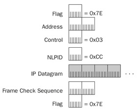
Figure 2-9: Frame relay encapsulation for IP datagrams, showing the Frame Relay header and trailer.
| More Info |
HDLC, as the basis for frame relay encapsulation of IP datagrams, is described in RFC 2427, which can be found in the Rfc folder on the companion CD-ROM. |
The fields in the Frame Relay header and trailer are defined as follows:
- FlagAs in PPP and X.25 frames, the Flag field is 1 byte long and is set to 0x7E to mark the beginning and end of the Frame Relay frame. Bit stuffing is used on synchronous links to prevent the occurrence of the FLAG character within the Frame Relay frame.
- AddressThe Address field is multiple bytes long (typically 2 bytes), and contains the Frame Relay virtual circuit identifier called the Data Link Connection Identifier (DLCI) and congestion indicators. The Address field's structure is discussed in the section entitled "Frame Relay Address Field," later in this chapter.
- ControlA 1-byte field set to 0x03 to indicate a UI frame.
- NLPIDA 1-byte field set to 0xCC to indicate an IP datagram.
- Frame Check SequenceA 2-byte CRC used for bit-level integrity verification in the Frame Relay frame. If a Frame Relay frame fails integrity verification, it is silently discarded.
Frame Relay Address Field
The Frame Relay Address field can be 1, 2, 3, or 4 bytes long. Typical frame relay implementations use a 2-byte Address field, as shown in Figure 2-10.
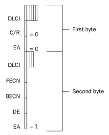
Figure 2-10: A 2-byte Frame Relay Address field.
The fields within the 2-byte Address field are defined as follows:
- DLCIThe first 6 bits of the first byte and the first 4 bits of the second byte comprise the 10-bit DLCI. The DLCI is used to identify the Frame Relay virtual circuit over which the Frame Relay frame is traveling. Like the X.25 LCN, the DLCI is only locally significant. Each Frame Relay switch changes the DLCI value as it forwards the Frame Relay frame. The devices at each end of a virtual circuit use a different DLCI value to identify the same virtual circuit. Table 2-1 lists the defined values for the DLCI.
Table 2-1: Defined Values for the Frame Relay DLCI DLCI Value
Use
0
In-channel signaling
1–15
Reserved
16–991
Assigned to user connections
992–1022
Reserved
1023
In-channel signaling
- Extended Address (EA)The last bit in each byte of the Address field is the EA bit. If this bit is set to 1, the current byte is the last byte in the Address field. For the 2-byte Address field, the value of the EA bit in the first byte of the Address field is 0, and the value of the EA bit in the second byte of theAddress field is 1.
- Command/Response (C/R)The seventh bit in the first byte of the Address field is the C/R bit. It currently is not used for frame relay operations, and is set to 0.
- Forward Explicit Congestion Notification (FECN)The fifth bit in the second byte of the Address field is the FECN bit. It is used to inform the destination Frame Relay node that congestion exists in the path from the source to the destination. The FECN bit is set to 0 by the source Frame Relay node, and set to 1 by a Frame Relay switch if it is experiencing congestion in the forward path. If the destination Frame Relay node receives a Frame Relay frame with the FECN bit set, the node can indicate the congestion condition to upper layer protocols that can implement receiver-side flow control. The interpretation of the FECN bit for IP traffic is not defined.
- Backward Explicit Congestion Notification (BECN)The sixth bit in the second byte of the Address field is the BECN bit. The BECN bit is used to inform the destination Frame Relay node that congestion exists in the path from the destination to the source (in the opposite direction in which the frame was traveling). The BECN bit is set to 0 by the source Frame Relay node, and set to 1 by a Frame Relay switch if it is experiencing congestion in the reverse path. If the destination Frame Relay node receives a Frame Relay frame with the BECN bit set, the node can indicate the congestion condition to upper layer protocols that can implement sender-side flow control. The interpretation of the BECN bit for IP traffic is not defined.
- Discard Eligibility (DE)The seventh bit in the second byte of the Address field is the DE bit. Frame Relay switches use the DE bit to decide which frames to discard during a period of congestion. Frame Relay switches consider the frames with the DE bit set to be a lower priority and discards them first. The initial Frame Relay switch sets the DE bit to 1 on a frame when a customerhas exceeded the CIR for the virtual circuit.
The maximum-sized frame that can be sent across a frame relay network varies according to the frame relay provider. RFC 2427 requires all frame relay networks to support a minimum frame size of 262 bytes, and a maximum frame size of 1600 bytes, although maximum frame sizes of up to 4500 bytes are common. Using a maximum frame size of 1600 bytes and a 2-byte address field, the IP MTU for frame relay is 1592.
ATM
ATM, or cell relay, is the latest innovation in broadband networking and is destined to eventually replace most existing WAN technologies. As with frame relay, ATM provides a connection-oriented, unreliable delivery service. ATM allows for the establishment of a connection between sites, but reliable communication is the responsibility of an upper layer protocol such as TCP.
ATM improves on the performance of frame relay. Instead of using variable-lengthframes, ATM takes a LAN traffic protocol data unit (PDU) such as an IP datagram and segments it into 48-byte segments. A 5-byte ATM header is added to each segment. The 53-byte ATM frames consisting of the segments of the IP datagram are sent over the ATM network, which the destination then reassembles. The fixed-length 53-byte ATM frame, known as an ATM cell, allows the performance of the ATM-switching network to be optimized.
ATM is available today as a PVC or an SVC through an ATM-switched network. ATM has been demonstrated at data rates up to 9.6 gigabits per second (Gbps) using SONET, an international specification for fiber-optic communication. ATM is a scalable solution for data, voice, audio, fax, and video, and can accommodate all of these information types simultaneously. ATM combines the benefits of circuit switching (fixed-transit delay and guaranteed bandwidth) with the benefits of packet switching (efficiency for bursty traffic).
The ATM Cell
The ATM cell consists of a 5-byte ATM header and a 48-byte payload. The following are two types of ATM headers:
- User network interface (UNI) headerThe ATM header that exists within a private network or between a customer site and a public ATM service provider.
- Network-to-network interface (NNI) headerThe ATM header that exists within a public ATM service provider's network.
Figure 2-11 shows the ATM cell header format at either a public or private UNI.
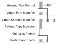
Figure 2-11: The ATM header format that exists at the ATM UNI.
The fields in the ATM header are defined as follows:
- Generic Flow Control (GFC)A 4-bit field that was originally added to support the connection of ATM networks to shared access networks such as aDistributed Queue Dual Bus (DQDB) ring. The GFC field was designed to give the UNI 4 bits in which to negotiate multiplexing and flow control among cells of a single ATM virtual circuit. However, the use and exact values of the GFC field have not been standardized, so the value is always set to 0x0.
- Virtual Path Identifier (VPI)The identifier of the virtual path for this particular cell. VPIs for a particular ATM virtual circuit are discovered during the virtual-circuit setup process for SVCs, and they are manually configured for PVCs. At the UNI, the VPI is 8 bits, allowing up to 256 different virtual paths. VPI 0 exists by default on all ATM equipment and is used for administrative purposes, such as signaling to create and delete dynamic ATM connections.
- Virtual Channel Identifier (VCI)The identifier of the virtual channel within the specified virtual path. Like VPIs, VCIs are dynamically allocated for SVC connections and manually configured for PVC connections. The VCI is 16 bits, allowing up to 65,536 different virtual channels for each virtual path. For each VPI, the ITU reserves VCIs 0 through 15, and the ATM Forum reserves VCIs 16 through 32. The reserved VCIs are used for signaling, operation and maintenance, and resource management.
The combination of VPI and VCI identifies the virtual circuit for a given ATM cell and comprises the ATM routing information that is used by ATM switches to forward the cell to its destination. The VPI/VCI combination acts as a local virtual circuit identifier in the same way as an LCN in X.25 and the DLCI in frame relay.
- Payload Type Indicator (PTI)A 3-bit field consisting of the following fields:
- ATM Cell TypeThe first bit of the PTI field is used as an indicator of the type of ATM cell. Set to 0 to indicate user data, and set to 1 to indicateoperations, administration, and management (OA&M) data.
- Explicit Forward Congestion Indication (EFCI)The second bit of the PTI field is used as an indicator of whether the cell experienced congestion in its journey from the source to the destination. The source sets the EFCI bit to 0. If an interim switch is experiencing congestion during the forwarding of the cell, the switch sets the bit to 1. Once set to 1, all other switches in the path leave this bit set at 1. Destination ATM endpoints can use the EFCI bit to implement receiver-side flow control mechanisms until cells with an EFCI bit set to 0 are received. The EFCI bit is similar in functionto the FECN bit used in frame relay.
- AAL5 Segmentation FlagUsed in user ATM cells to indicate the last cell in a block for ATM Adaptation Layer 5 (AAL5). For nonuser ATM cells, the third bit is used for OA&M functions. AAL5 is described in detail in thesection entitled "AAL5," later in this chapter.
- Cell Loss Priority (CLP)A 1-bit field that is used as a cell priority indicator. If set to 0, the cell is high priority and interim switches must make every effort to forward the cell successfully. If the CLP bit is set to 1, the interim switches can elect to discard the cell in congestion situations. The CLP bit is similarto the DE bit in frame relay. Setting the CLP bit to 1 can be done by theATM endpoint on creation, as a way to indicate a lower priority cell, or atthe ATM switch, if the cell is beyond the negotiated parameters of the vir-tual circuit (similar to bursting above the CIR in frame relay).
- Header Error Check (HEC)A 1-byte field that allows an ATM switch or ATM endpoint to correct a single-bit error, or to detect multibit errors in the first 4 bytes of the ATM header. Multibit errored cells are silently discarded. Note that the HEC checks only the ATM header and not the ATM payload. Checking the payload for errors is the responsibility of upper layer protocols.
Figure 2-12 shows the ATM cell header format at the public NNI.
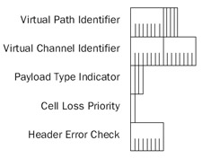
Figure 2-12: The ATM header format that exists at the ATM NNI.
The only differences between the UNI and NNI headers are as follows:
- No GFC fieldATM switches in an ATM service provider do not need a way to negotiate the multiplexing for various types of shared-access user connections.
- VPI is now 12 bits longThis allows up to 4096 virtual paths per transmission path. With an extended VPI, ATM service providers have more flexibility to perform virtual path switching and to create a backbone architecture to support trunk lines in the voice telephone system.
ATM Architecture
The ATM architectural model (known as the B-ISDN/ATM Model) has three main layers, as shown in Figure 2-13.
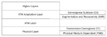
Figure 2-13: The ATM architectural model, showing the three main layers and their sublayers.
Physical Layer
The Physical Layer provides for the transmission and reception of ATM cells across a physical medium between two ATM devices. The Physical Layer is subdivided into a Physical Medium Dependent (PMD) sublayer and Transmission Convergence (TC) sublayer.
The PMD sublayer is responsible for the transmission and reception of individual bits on a physical medium. These responsibilities encompass bit-timing, signal-encoding, interfacing with the physical medium, and the physical medium itself. ATM does not rely on any specific bit rate, encoding scheme, or medium. Various specifications for ATM exist for coaxial cable, shielded and unshielded twisted-pair wire, and optical fiber at speeds ranging from 64 Kbps through 9.6 Gbps.
The TC sublayer acts as a converter between the bit stream at the PMD sublayer and ATM cells. When transmitting, the TC sublayer maps ATM cells onto the format of the PMD sublayer (such as DS-3 or SONET frames). Because a continuous stream of bytes isrequired, idle cells occupy portions in the ATM cell stream that are not used. The receiver silently discards idle cells so they are never passed to the ATM layer for processing. The TC sublayer also is responsible for generation and verification of the HEC field for each cell, and for determining ATM cell delineation (where the ATM cells begin and end).
ATM Layer
The ATM Layer provides cell multiplexing, demultiplexing, and VPI/VCI routing functions. In addition, the ATM Layer is responsible for supervising the cell flow to ensure that all connections remain within their negotiated cell throughput limits. The ATM Layer can take corrective action so that those connections operating outside their negotiated parameters do not affect those connections that are obeying their negotiated connection parameters. Additionally, the ATM Layer ensures that the cell sequence from any source is maintained.
The ATM Layer multiplexes and demultiplexes, routes ATM cells, and ensures theirsequence from end to end. However, if a switch drops a cell because of congestion or corruption, it is not the ATM Layer's responsibility to correct the dropped cell through retransmission or to notify other layers of the dropped cell. Layers above the ATM Layer must sense the lost cell and decide whether to correct for its loss.
ATM Adaptation Layer
The ATM Adaptation Layer (AAL) is responsible for the creation and reception of 48-byte payloads using the ATM Layer on behalf of different types of applications. The AAL is subdivided between the Convergence sublayer (CS) and the Segmentation and Reassembly (SAR) sublayer. ATM adaptation is necessary to interface the cell-based technology at the ATM Layer, to the bit-stream technology of digital devices (such as telephones and video cameras), and the packet-stream technology of modern data networks (such as frame relay or LAN protocols, including TCP/IP).
Convergence Sublayer
The CS is the last place that an application block of data (also known as a PDU) has its original form before being handed to the SAR sublayer for division into 48-byte ATM payloads. The CS is responsible for an encapsulation that allows the application data block to be distinguished and handed to the destination application. The CS is further subdivided into two sublayers: the Common Part CS (CPCS), which must be implemented, and the Service Specific CS (SSCS), which might be implemented depending on the actual service. If the SSCS is not implemented, it does not add headers to the data being sent.
SAR Sublayer
On the sending side, the SAR sublayer takes the block of data from the CS (hereafter known as the CPCS PDU) and divides it into 48-byte segments. Each segment is then handed to the ATM Layer for final ATM encapsulation. On the receiving side, the SAR sublayer receives each ATM cell and reassembles the CPCS PDU. The completed CPCS PDU is then handed up to the CS for processing.
To provide a standard mechanism for the CPCS and SAR sublayers, the ITU-T has created a series of ATM Adaptation Layers as follows:
- AAL1Designed for isochronous (time-dependent), constant bit rate, connection-oriented applications, and used to provide circuit emulation.
- AAL2Designed for isochronous, variable bit rate, connection-oriented applications, and used for compressed voice or video.
- AAL3/4Designed for non-isochronous, variable bit rate, connection-oriented or connectionless applications, and used for X.25 or LAN traffic.
- AAL5Designed for non-isochronous, variable bit rate, connection-orientedor connectionless applications. It is typically used for LAN traffic such as IP datagrams because its overhead is lower than that of AAL3/4.
AAL5
AAL5 provides a way for non-isochronous, variable bit rate, connectionless applications to send and receive data. The data communications industry developed AAL5 as a straightforward framing at the CPCS that tends to behave like existing LAN technologies such as Ethernet. AAL5 is the AAL of choice when sending connection-oriented (frame relay) or connectionless (IP or IPX) LAN protocol traffic over an ATM network.
AAL5 Framing
Figure 2-14 shows the framing that occurs at AAL5.
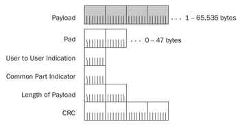
Figure 2-14: AAL5 framing, showing the payload and the AAL5 trailer.
The fields in the AAL5 frame are defined as follows:
- PayloadThe block of data that an application sends. The size can vary from 1 byte to 65,535 bytes.
- PadOf variable length (0–47 bytes). The Pad field is present to make theentire CPCS PDU an integral number of 48-byte units.
- User To User IndicationA 1-byte field that is used to transfer information between AAL users. The exact use of this byte is not defined and is left to the implementation.
- Common Part IndicatorA 1-byte field that is currently used only for alignment processes so that the nonpadded portion of the AAL5 trailer is on a 64-bit boundary.
- Length of PayloadA 2-byte field used to indicate the length in bytes of the Payload field so that the receiver can discard the Pad field.
- CRCA 4-byte CRC that provides bit-level integrity services on the entire CPCS PDU. The AAL5 CRC uses the same checksum algorithm as IEEE 802 network technologies such as Ethernet (IEEE 802.3) and Token Ring (IEEE 802.5).
The SAR sublayer for AAL5 segments the CPCS PDU along 48-byte boundaries and passes the segments to the ATM Layer for encapsulation with an ATM header. On the receiving side, the SAR sublayer reassembles the incoming 48-byte ATM payloads and passes the result to the CPCS. The SAR uses the AAL5 Segmentation Flag field, the third bit in the PTI field, to indicate when the last 48-byte unit in a CPCS PDU is sent. On the receiving side, when the ATM cell is received with the AAL5 Segmentation Flag field set, the ATM Layer indicates this to AAL5 so that analysis of the full CPCS PDU can begin.
Sending an IP Datagram Over an ATM Network
The method of sending IP datagrams over an ATM network using AAL5 is known as classical IP over ATM, and is described in RFCs 1577 and 1626. To ensure compatibility with IP datagrams sent over a Switched Multimegabit Data Service (SMDS) network, another cell-based WAN technology, IP datagrams have a maximum size of 9180 bytes. Figure 2-15 shows IP datagram encapsulation using AAL5.
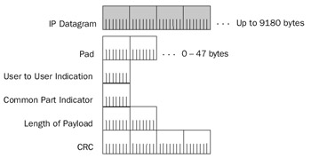
Figure 2-15: IP datagram encapsulation using AAL5.
| More Info |
RFCs 1577 and 1626 describe classical IP over ATM. These can be found in the Rfc folder on the companion CD-ROM. |
At the SAR sublayer, the CPCS PDU is segmented into 48-byte units that become the ATM payloads for a stream of ATM cells. When the last cell in the CPCS PDU is sent, the AAL5 Segmentation Flag field is set to 1. When the last cell is received, the receiver uses the CRC to check the validity of the bits in the CPCS PDU. If the CRC is valid, the Length field is used to discard the Pad field. The AAL trailer is stripped, and the end result is the originally transmitted IP datagram that is then passed to the IP layer for processing.
For a given ATM virtual circuit, IP datagrams must be sent one at a time. The cells of multiple IP datagrams cannot be mixed on the same virtual circuit. The ATM header contains no information to signify which cells belong to which CPCS PDU. ATM segmentation differs from IP fragmentation in this regard. With IP fragmentation, the Identification field serves to group all the fragments of the original IP datagram together. An IP router can send the fragments of different IP packets alternately without a reconstruction issue on the receiving side. With ATM segmentation, there is no fragment ID field or equivalent that can be used to differentiate CPCS PDUs.
Example of Sending an IP Datagram
Figure 2-16 shows an example of sending a 128-byte IP datagram across an ATM network using AAL5.
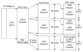
Figure 2-16: Example of sending an IP datagram over ATM using AAL5 encapsulation.
The AAL5 trailer with an 8-byte Pad field is added to the IP datagram. The 8 bytes of the Pad field make the entire AAL5 CPCS PDU 144 bytes, an integral multiple of 48. The resulting AAL5 CPCS PDU is then segmented into three 48-byte segments. Each 48-byte segment becomes the payload of an ATM cell sent in sequence to the destination ATM endpoint on the virtual circuit. When the last segment is sent, the AAL5 Segmentation Flag field is set to 1.
| Note |
For the Windows Server 2003 family, ATM traffic captured with Network Monitor does not display the individual ATM cells or the ATM header. The ATM header displayed with Network Monitor contains a simulated source and destination MAC address and the VPI and VCI fields for the virtual circuit. |
Multiprotocol Encapsulation with AAL5
When multiple protocols are sent over the same ATM virtual circuit, a protocol identifier is needed to differentiate the various Network Layer protocols.
| More Info |
Multiprotocol encapsulation over ATM is described in RFC 1483, which can be found in the Rfc folder on the companion CD-ROM. |
To add a protocol identifier to the CPCS PDU, the Sub-Network Access Protocol (SNAP) method used by IEEE 802.x networks is used. Figure 2-17 shows multiprotocol encapsulation over AAL5.
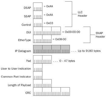
Figure 2-17: Multiprotocol encapsulation for AAL5, using the LLC and SNAP headers.
As described in Chapter 1, "Local Area Network (LAN) Technologies," the SNAP header consists of a Logical Link Control (LLC) header and a SNAP header. Within the LLC header, the Destination Service Access Point is set to 0xAA, the Source Service Access Point is set to 0xAA, and the Control field is set to 0x03. Within the SNAP header, the Organization Unique Identifier is set to 00-00-00 and the EtherType field is set to 0x08-00 for IP. When the ATM virtual circuit is created, both ATM endpoints negotiate the use of either single-protocol or multiprotocol AAL5 encapsulation.
Summary
Typical WAN technology encapsulations used by the Windows Server 2003 family and Windows XP provide delimitation, addressing, protocol identification, and bit-level integrity services. IP datagrams and ARP messages sent over point-to-point WAN links can be encapsulated using SLIP, PPP, or MP. IP datagrams and ARP messages sent over NBMA links such as X.25, frame relay, or ATM use the appropriate single or multiprotocol encapsulation.
Part I - The Network Interface Layer
- Local Area Network (LAN) Technologies
- Wide Area Network (WAN) Technologies
- Address Resolution Protocol (ARP)
- Point-to-Point Protocol (PPP)
Part II - Internet Layer Protocols
- Internet Protocol (IP) Basics
- Internet Protocol (IP) Addressing
- Internet Protocol (IP) Routing
- Internet Control Message Protocol (ICMP)
- Internet Group Management Protocol (IGMP)
- Internet Protocol Version 6 (IPv6)
Part III - Transport Layer Protocols
- User Datagram Protocol
- Transmission Control Protocol (TCP) Basics
- Transmission Control Protocol (TCP) Connections
- Transmission Control Protocol (TCP) Data Flow
- Transmission Control Protocol (TCP) Retransmission and Time-Out
Part IV - Application Layer Protocols and Services
- Dynamic Host Configuration Protocol (DHCP) Server Service
- Domain Name System (DNS)
- Windows Internet Name Service (WINS)
- File and Printer Sharing
- RADIUS and Internet Authentication Service
- Internet Information Services (IIS) and the Internet Protocols
- Internet Protocol Security (IPSec)
- Virtual Private Networks (VPNs)
EAN: N/A
Pages: 216
