Transmission Control Protocol (TCP) Connections
TCP is a connection-oriented protocol. Before data can flow on a TCP connection, the connection must be formally established through a handshake process. To gracefully stop the flow of data on a TCP connection and release the resources of the connection, it must be terminated through a similar handshake process.
The TCP Connection
A TCP connection is a bidirectional, full-duplex logical circuit between two processes(Application Layer protocols) in an IP internetwork. The TCP connection's endpoints are identified by an [IP address, TCP port] pair. The connection is uniquely identified by both endpoints: [IP address 1, TCP port 1, IP address 2, TCP port 2]. TCP uses those four numbers to demultiplex the data portion of the TCP segment to the proper Application Layer process.
A TCP connection can be visualized as a bidirectional data pipe containing two logical pipes between the two TCP peers, as Figure 13-1 illustrates. One logical pipe is used for outbound data and the other logical pipe is used for inbound data (relative to the TCP peer). The outbound data pipe for one TCP peer is the inbound data pipe for the other TCP peer.
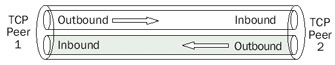
Figure 13-1: A TCP connection showing both inbound and outbound logical pipes.
TCP connections are:
- Established through a handshake process in which both TCP peers agree to create a TCP connection
- Maintained through a periodic keepalive process that ensures that both TCP peers are active on the connection
- Terminated through a handshake process in which both TCP peers agree to close the TCP connection
TCP connections can also be reset by either TCP peer.
TCP Connection Establishment
To create a TCP connection over which full-duplex data can begin to flow, each TCP peer must learn the following information from the other TCP peer:
- The starting sequence number for data sent on the inbound pipe
- The size of the buffer to receive data sent on the outbound pipe (the receive window size of the other TCP peer)
- The maximum segment size (MSS) that can be received
- The TCP options that are supported
This information is learned through an exchange of three TCP segments called the TCP connection establishment process, or the TCP three-way handshake.
To create a TCP connection, a server system must allow a TCP connection, and aclient system must initiate a TCP connection. The server system issues a passive OPEN function call to permit incoming connection requests on a specific port number. Thisfunction call does not create any TCP traffic. The client system issues an active OPEN function call, which creates and sends the first segment of the TCP three-way handshake.
Figure 13-2 displays the TCP connection establishment process, showing the three TCP segments that are exchanged and the information in the TCP header that is vital to the connection establishment. Prior to segment 1, TCP Peer 2 issued a passive OPEN toreceive TCP connection requests. TCP Peer 1 issues an active OPEN and creates segment 1. Segments 2 and 3 complete the connection establishment process. The vertical arrows show the passage of time during the connection establishment process.
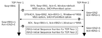
Figure 13-2: The TCP connection establishment process, showing the exchange of three TCP segments.
Segment 1 The Synchronize (SYN) Segment
TCP Peer 1 sends the first TCP segment, known as the SYN segment, to TCP Peer 2. The SYN segment establishes TCP connection parameters, such as the Initial Sequence Number (ISN) that TCP Peer 1 uses. The SYN segment as sent by a computer running a member of the Microsoft Windows Server 2003 family or Windows XP contains the following fields in the TCP header:
- Destination PortSet to the TCP port number of the passive OPEN on TCP Peer 2. For typical TCP connections, the destination port in the SYN segment is a well-known TCP port in the range of 1 to 1023.
- Source PortSet to the local TCP port number of the active OPEN on TCP Peer 1. For typical TCP connections, the source port is a dynamically allocated port in the range of 1024 to 5000.
- Sequence NumberSet to the ISN for data to be sent by TCP Peer 1 for the outbound data pipe (ISN1 in Figure 13-2). A TCP peer running a member of the Windows Server 2003 family or Windows XP chooses the ISN based on a startup-derived, 2048-bit random key and an RC4-based random number toreduce the predictability of the next TCP connection's ISN.
- Acknowledgment NumberSet to 0. Because the Acknowledgment (ACK) flag is not set, the Acknowledgment Number field is not significant. Only after a TCP peer learns the sequence number for inbound data on the connection can the ACK flag be set and the Acknowledgment Number field set to theappropriate value.
- SYN FlagIndicates that the segment contains the ISN for data sent by TCP Peer 1.
- WindowSet to a default value, indicating an initial value for the size of TCP Peer 1's receive buffer.
- MSS in the MSS TCP OptionSet to the maximum-sized TCP segment that TCP Peer 1 can receive.
- Selective Acknowledgment (SACK)-Permitted TCP OptionIncluded to indicate that TCP Peer 1 can receive and interpret the SACK option includedin TCP segments that TCP Peer 2 sends.
The following Network Monitor trace (Frame 1 of Capture 13-01, included in theCaptures folder on the companion CD-ROM) shows a SYN segment for a File Transfer Protocol (FTP) session:
+ ETHERNET: ETYPE = 0x0800 : Protocol = IP: DOD Internet Protocol
+ IP: ID = 0x28EA; Proto = TCP; Len: 48
 TCP: ....S., len: 0, seq:3928116524-3928116524, ack: 0, win:16384, src: 1162
 dst: 21 (FTP)
 TCP: Source Port = 0x048A
 TCP: Destination Port = FTP [control]
 TCP: Sequence Number = 3928116524 (0xEA224D2C)
 TCP: Acknowledgment Number = 0 (0x0)
 TCP: Data Offset = 28 (0x1C)
 TCP: Reserved = 0 (0x0000)
 TCP: Flags = 0x02 : ....S.
 TCP: ..0..... = No urgent data
 TCP: ...0.... = Acknowledgment field not significant
 TCP: ....0... = No Push function
 TCP: .....0.. = No Reset
 TCP: ......1. = Synchronize sequence numbers
 TCP: .......0 = No Fin
 TCP: Window = 16384 (0x4000)
 TCP: Checksum = 0x854E
 TCP: Urgent Pointer = 0 (0x0)
 TCP: Options
 TCP: Maximum Segment Size Option
 TCP: Option Type = Maximum Segment Size
 TCP: Option Length = 4 (0x4)
 TCP: Maximum Segment Size = 1460 (0x5B4)
 TCP: Option Nop = 1 (0x1)
 TCP: Option Nop = 1 (0x1)
 TCP: SACK Permitted Option
 TCP: Option Type = Sack Permitted
 TCP: Option Length = 2 (0x2)
Segment 2 The SYN ACK Segment
After receipt of the SYN segment, TCP Peer 2 sends the second TCP segment known as the SYN-ACK segment to TCP Peer 1. The SYN-ACK segment establishes TCP connec-tion parameters that TCP Peer 2 uses, such as the ISN, and acknowledges TCP connectionparameters used by TCP Peer 1. The SYN-ACK segment as sent by a computer running a member of the Windows Server 2003 family or Windows XP contains the following fields in the TCP header:
- Destination PortSet to the Source Port of the SYN segment.
- Source PortSet to the local TCP port number of the passive OPEN on TCP Peer 2 as indicated by the Destination Port number of the SYN segment.
- Sequence NumberSet to the ISN for data to be sent by TCP Peer 2 for the outbound data pipe (ISN2 in Figure 13-2). A TCP peer running a member of the Windows Server 2003 family or Windows XP chooses the ISN based on a startup-derived, 2048-bit random key and an RC4-based random number toreduce the predictability of the next TCP connection's ISN.
- Acknowledgment NumberSet to the value of the TCP Peer 1's ISN plus 1 (ISN1 + 1). The SYN flag occupies a single octet of the sequence space of Peer 1. The acknowledgment number is the next octet in the byte stream that TCP Peer 2 expects to receive. If the SYN flag acts as a single octet of nondata, the next octet that TCP Peer 2 expects to receive is actual data, and must therefore begin with ISN1 + 1.
- SYN FlagIndicates that the segment contains the ISN for data sent by TCP Peer 2.
- ACK FlagIndicates that the Acknowledgment Number field is significant.
- WindowSet to an application-specified value or the value of an integral number of MSS-sized segments according to an operating system default value. This value indicates an initial value for the size of TCP Peer 2's receive buffer (n*MSS in Figure 13-2). For Windows Server 2003 family– or Windows XP–based TCP/IP hosts using Ethernet, the default receive window size is 17,520 octets, or 12 MSS segments (at 1460 octets per segment).
- MSS in the MSS TCP OptionSet to the maximum-sized TCP segment that TCP Peer 2 can receive.
- SACK-Permitted TCP Option Indicates that TCP Peer 2 can receive andinterpret the SACK option included in TCP segments that TCP Peer 1 sends.
The following Network Monitor trace (Frame 2 of Capture 13-01, included in theCaptures folder on the companion CD-ROM) shows a SYN-ACK segment for an FTP session (continued from the previous SYN segment):
+ ETHERNET: ETYPE = 0x0800 : Protocol = IP: DOD Internet Protocol
+ IP: ID = 0xDFAB; Proto = TCP; Len: 48
 TCP: .A..S., len: 0, seq:1035688768-1035688768, ack:3928116525,
 win:17520, src: 21 (FTP) dst: 1162
 TCP: Source Port = FTP [control]
 TCP: Destination Port = 0x048A
 TCP: Sequence Number = 1035688768 (0x3DBB5B40)
 TCP: Acknowledgment Number = 3928116525 (0xEA224D2D)
 TCP: Data Offset = 28 (0x1C)
 TCP: Reserved = 0 (0x0000)
 TCP: Flags = 0x12 : .A..S.
 TCP: ..0..... = No urgent data
 TCP: ...1.... = Acknowledgment field significant
 TCP: ....0... = No Push function
 TCP: .....0.. = No Reset
 TCP: ......1. = Synchronize sequence numbers
 TCP: .......0 = No Fin
 TCP: Window = 17520 (0x4470)
 TCP: Checksum = 0xE7D1
 TCP: Urgent Pointer = 0 (0x0)
 TCP: Options
 TCP: Maximum Segment Size Option
 TCP: Option Type = Maximum Segment Size
 TCP: Option Length = 4 (0x4)
 TCP: Maximum Segment Size = 1460 (0x5B4)
 TCP: Option Nop = 1 (0x1)
 TCP: Option Nop = 1 (0x1)
 TCP: SACK Permitted Option
 TCP: Option Type = Sack Permitted
 TCP: Option Length = 2 (0x2)
Segment 3 The ACK Segment
After receipt of the SYN-ACK segment, TCP Peer 1 sends the third TCP segment, known as the ACK segment, to TCP Peer 2. The ACK segment establishes the final TCP connection parameters used by TCP Peer 1 and acknowledges TCP connection parameters that TCP Peer 2 uses. The ACK segment, as sent by a computer running a member of the Windows Server 2003 family or Windows XP, contains the following fields in the TCP header:
- Destination PortSet to the Source Port of the SYN-ACK segment.
- Source PortSet to the local TCP port number of the active OPEN on TCP Peer 1 as indicated by the Destination Port number of the SYN-ACK segment.
- Sequence NumberSet to ISN1 + 1.
- Acknowledgment NumberSet to the value of the TCP Peer 2's ISN plus 1 (ISN2 + 1). The SYN flag occupies a single octet of the sequence space of TCP Peer 2. The acknowledgment number is the next octet in the byte streamthat TCP Peer 1 expects to receive. If the SYN flag is acting as a single octetof nondata, the next octet that TCP Peer 1 expects to receive is actual data, and must therefore begin with ISN2 + 1.
- ACK FlagIndicates that the Acknowledgment Number field is significant.
- WindowSet to an application-specified value, or the value of an integral number of MSS-sized segments, according to an operating system default value. This value indicates an initial value for the size of TCP Peer 1's receive buffer (n*MSS in Figure 13-2). For Windows Server 2003– or Windows XP–based TCP/IP hosts using Ethernet, the default receive window size is 17,520 octets, or 12 MSS segments (at 1460 octets per segment).
The following Network Monitor trace (Frame 3 of Capture 13-01, included in the Captures folder on the companion CD-ROM) shows an ACK segment for an FTP session (continued from the previous SYN-ACK segment):
 + ETHERNET: ETYPE = 0x0800 : Protocol = IP: DOD Internet Protocol
+ IP: ID = 0x28EB; Proto = TCP; Len: 40
 TCP: .A...., len: 0, seq:3928116525-3928116525, ack:1035688769,
 win:17520, src: 1162 dst: 21 (FTP)
 TCP: Source Port = 0x048A
 TCP: Destination Port = FTP [control]
 TCP: Sequence Number = 3928116525 (0xEA224D2D)
 TCP: Acknowledgment Number = 1035688769 (0x3DBB5B41)
 TCP: Data Offset = 20 (0x14)
 TCP: Reserved = 0 (0x0000)
 TCP: Flags = 0x10 : .A....
 TCP: ..0..... = No urgent data
 TCP: ...1.... = Acknowledgment field significant
 TCP: ....0... = No Push function
 TCP: .....0.. = No Reset
 TCP: ......0. = No Synchronize
 TCP: .......0 = No Fin
 TCP: Window = 17520 (0x4470)
 TCP: Checksum = 0x1496
 TCP: Urgent Pointer = 0 (0x0)
Results of the TCP Connection
The results of the TCP connection establishment process are as follows:
- Each TCP peer knows the sequence number of the first octet of data to be sent on the connection (TCP Peer 1's Acknowledgment Number field is set to TCP Peer 2's Sequence Number field; TCP Peer 2's Acknowledgment Number field is set to TCP Peer 1's Sequence Number field).
- Each TCP peer knows the MSS that can be sent on the connection. The connection's MSS is the minimum of the two MSSs advertised by TCP Peer 1 and TCP Peer 2. Path Maximum Transmission Unit (PMTU) Discovery adjusts the initial MSS for the duration of connection. For more information on PMTU Discovery, see Chapter 8, "Internet Control Message Protocol (ICMP)."
- Each TCP peer knows the size of the other peer's receive buffer (the window size) indicating the maximum amount of data that can be sent without waiting for an ACK and updated window size. Although a large amount of data can be sent, TCP peers use the slow start and congestion avoidance algorithms to slowly scale the amount of data sent to avoid congesting the internetwork.
- Each TCP peer is aware that the other peer is capable of receiving selective acknowledgments using the SACK TCP option. For more information on selective acknowledgment, see Chapter 14, "Transmission Control Protocol (TCP) Data Flow."
Registry Settings for TCP Connections
The TCP connection establishment process is controlled by the following registry settings:
TcpMaxConnectRetransmissions
Location:
HKEY_LOCAL_MACHINESYSTEMCurrentControlSetServicesTcpipParameters
Data type: REG_DWORD
Valid range: 0-255
Default value: 2
Present by default: No
TcpMaxConnectRetransmissions sets how many SYN segment retransmissions are sent when attempting to establish a TCP connection. The retransmission time-out (RTO) is doubled between each retransmission. With the initial RTO of 3 seconds and the default value of TcpMaxConnectRetransmissions of 2, it takes 21 seconds to time out a TCP connection attempt (initial SYN, wait 3 seconds, first retransmitted SYN, wait 6 seconds, second transmitted SYN, wait 12 seconds).
The following summary of a Network Monitor trace (Capture 13-02, included in theCaptures folder on the companion CD-ROM) shows this behavior:
1 0.000 TCP_Peer_1 Intel 123456 TCP ....S., len: 0, seq:
 748701-748704, ack: 0
2 2.923 TCP_Peer_1 Intel 123456 TCP ....S., len: 0, seq:
 748701-748704, ack: 0
3 6.009 TCP_Peer_1 Intel 123456 TCP ....S., len: 0, seq:
 748701-748704, ack: 0
This summary trace displays the elapsed time between successive frames.
TcpNumConnections
Location:
HKEY_LOCAL_MACHINESYSTEMCurrentControlSetServicesTcpipParameters
Data type: REG_DWORD
Valid range: 0-0xFFFFFE
Default value: 0xFFFFFE
Present by default: No
TcpNumConnections sets the maximum number of TCP connections that can be open. By default, 16,777,214 (0xFFFFFE) connections can be open.
TCP Half Open Connections
A TCP half-open connection, illustrated in Figure 13-3, is a TCP connection that has not completed the connection establishment process. A SYN segment has been received and a SYN-ACK has been sent, but the final ACK has not been received. Until the final ACK is received, data cannot be sent on the connection.
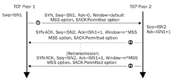
Figure 13-3: A TCP half-open connection showing the SYN segment and retransmissions of the SYN-ACK segment.
Although the SYN-ACK segment contains no data, the SYN flag occupies a singlebyte of the sequence space and is treated as data. Therefore, TCP retransmission andtime-out behaviors used for recovering from lost data are used to recover from a lostSYN-ACK segment. In the case of retransmitting a SYN-ACK segment, the default time-out is 3 seconds and the SYN-ACK is retransmitted twice by default. Therefore, the first SYN-ACK is sent, 3 seconds later the first retransmission is sent, and 6 seconds later the second retransmission is sent. After waiting 12 seconds for a response to the final retransmission, the connection is abandoned and the memory and the connection's internal table entries are released. A total of 21 seconds elapse from the time the first SYN-ACK is sent until the connection is abandoned.
The SYN Attack
The SYN attack is a denial-of-service attack that exploits the retransmission and time-out behavior of the SYN-ACK to create a large number of half-open connections. Depending on the TCP/IP protocol implementation, a large number of half-open connections could do any of the following:
- Use all available memory.
- Use all possible entries in the TCP Transmission Control Block (TCB), an internal table used to track TCP connections. Once the half-open connections use all the entries, further connection attempts are responded to with a TCP connection reset. TCP connection resets are discussed in the section "TCP Connection Reset," later in this chapter.
- Use all available half-open connections. After all the half-open connections are used, further connection attempts are responded to with a TCP connection reset.
To create a large number of TCP half-open connections, malicious users send a large number of SYN segments from a spoofed IP address and TCP port number. The spoofed IP address and TCP port number are for a process that does not respond to the SYN-ACKs being sent by the attacked host. SYN attacks typically are used to render Internet servers inoperative.
To see a SYN attack in progress on a computer running a member of the Windows Server 2003 family or Windows XP, use the NETSTAT command to display the active TCP connections. For example:
c:>netstat -n -p tcp
 Active Connections
 Proto Local Address Foreign Address State
 TCP 127.0.0.1:1030 127.0.0.1:1032 ESTABLISHED
 TCP 127.0.0.1:1032 127.0.0.1:1030 ESTABLISHED
 TCP 10.1.1.5:21 192.168.0.1:1025 SYN_RECEIVED
 TCP 10.1.1.5:21 192.168.0.1:1026 SYN_RECEIVED
 TCP 10.1.1.5:21 192.168.0.1:1027 SYN_RECEIVED
 TCP 10.1.1.5:21 192.168.0.1:1028 SYN_RECEIVED
 TCP 10.1.1.5:21 192.168.0.1:1029 SYN_RECEIVED
 TCP 10.1.1.5:21 192.168.0.1:1030 SYN_RECEIVED
 TCP 10.1.1.5:21 192.168.0.1:1031 SYN_RECEIVED
 TCP 10.1.1.5:21 192.168.0.1:1032 SYN_RECEIVED
 TCP 10.1.1.5:21 192.168.0.1:1033 SYN_RECEIVED
 TCP 10.1.1.5:21 192.168.0.1:1034 SYN_RECEIVED
 TCP 10.1.1.5:21 192.168.0.1:1035 SYN_RECEIVED
This is an example of a SYN attack. There are a number of TCP connections in the SYN_ RECEIVED state, and the foreign address is a spoofed private address with incrementally increasing TCP port numbers. The SYN_RECEIVED is the state of a TCP connection that has received a SYN, sent a SYN-ACK, and is waiting for the final ACK. TCP connection states are discussed in greater detail later in this chapter in the section "TCP Connection States."
TCP/IP for the Windows Server 2003 family and Windows XP has been modified from previous versions to detect and defend against a SYN attack in progress by using the following registry settings:
TcpMaxConnectResponseRetransmissions
Location:
HKEY_LOCAL_MACHINESYSTEMCurrentControlSetServicesTcpipParameters
Data type: REG_DWORD
Valid range: 0–255
Default value: 2
Present by default: No
TcpMaxConnectResponseRetransmissions sets the number of retransmissions of a SYN-ACK for half-open connections. For values greater than 1, TCP/IP uses SYN attack protection.
SynAttackProtect
Location:
HKEY_LOCAL_MACHINESYSTEMCurrentControlSetServices TcpipParameters
Data type: REG_DWORD
Valid range: 0–1
Default value: 0
Present by default: No
SynAttackProtect disables SYN attack protection (when the value is 0) or enables SYN attack protection (when the value is 1). When enabled, half-open connections time out more quickly if a SYN attack is detected.
TcpMaxHalfOpen
Location:
HKEY_LOCAL_MACHINESYSTEMCurrentControlSetServicesTcpipParameters
Data type: REG_DWORD
Valid range: 100-65535
Default value: 100 for Windows XP; Windows Server 2003, Web Edition; and
Windows Server 2003, Standard Edition; and 500 for Windows Server 2003,
Enterprise Edition; and Windows Server 2003, Datacenter Edition
Present by default: No
TcpMaxHalfOpen sets the maximum number of TCP connections in the SYN_RECEIVED state before SYN attack protection takes effect.
TcpMaxHalfOpenRetried
Location:
HKEY_LOCAL_MACHINESYSTEMCurrentControlSetServicesTcpipParameters
Data type: REG_DWORD
Valid range: 80-65535
Default value: 80 for Windows XP; Windows Server 2003, Web Edition; and
Windows Server 2003, Standard Edition; 400 for Windows Server 2003, Enterprise
Edition; and Windows Server 2003, Datacenter Edition
Present by default: No
TcpMaxHalfOpenRetried sets the maximum number of TCP connections in the SYN_RECEIVED state for which at least one retransmission has been sent before SYN attack protection takes effect.
TCP Connection Maintenance
A TCP connection can be maintained through the periodic exchange of a TCP keepalive segment, which is an ACK segment containing no data. The Sequence Number field in the TCP header of the keepalive segment is set to 1 less than the current sequence number for the outbound data stream. For example, if a TCP peer's next octet of data is 18745323, the TCP keepalive sent by the TCP peer has the Sequence Number field set to 18745322.
After receiving this ACK segment, the other TCP peer sends back an ACK segment with the Acknowledgment Number field set to the next octet that it expects to receive. In this example, the TCP peer sends an ACK segment with the Acknowledgment Number field set to 18745323. This simple exchange confirms that both TCP peers are still participating in the TCP connection.
Figure 13-4 shows the TCP keepalive.
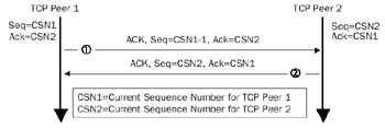
Figure 13-4: A TCP keepalive showing the sending of an exchange of ACK segments to confirm both ends of the connection are still present.
TCP keepalives for TCP/IP for the Windows Server 2003 family and Windows XP are disabled by default. If enabled through the use of the setsockopt() Windows Sockets function, a keepalive segment is sent every two hours by default, as controlled by the KeepAliveTime registry setting. Even if enabled, other upper layer protocols such as NetBIOS send their own keepalive. If the keepalive interval that the upper layer protocol uses is less than the TCP keepalive interval, TCP keepalives are never sent. For example, NetBIOS sessions over TCP/IP send a NetBIOS keepalive every 60 minutes. Therefore, TCP keepalives enabled for a NetBIOS session are never used.
The following registry settings control TCP keepalive behavior:
KeepAliveTime
Location:
HKEY_LOCAL_MACHINESYSTEMCurrentControlSetServicesTcpipParameters
Data type: REG_DWORD
Valid range: 0-0xFFFFFFFF
Default value: 0x6DDD00 (7,200,000)
Present by default: No
KeepAliveTime sets the number of milliseconds between each TCP keepalive segment if no data has been sent on the connection and if keepalives have been enabled on the connection. The default value of 7,200,000 milliseconds corresponds to two hours.
KeepAliveInterval
Location:
HKEY_LOCAL_MACHINESYSTEMCurrentControlSetServicesTcpipParameters
Data type: REG_DWORD
Valid range: 0-0xFFFFFFFF
Default value: 0x3E8 (1000)
Present by default: No
KeepAliveInterval sets the number of milliseconds between successive retransmissions of the keepalive segment when a response to the initial keepalive is not received. The number of TCP keepalive retransmissions is controlled by the TcpMaxDataRetransmissions registry setting, which has a default value of 5. After sending five TCP keepalive retransmissions, the connection is abandoned.
Therefore, with the default values of KeepAliveTime, KeepAliveInterval, and TcpMaxData-Retransmissions, a TCP connection on which keepalives have been enabled by theapplication is abandoned after two hours and six seconds.
Notice that for keepalives, the exponential backoff behavior between successive retransmissions is not done. For more information on the retransmission behavior of TCP, see Chapter 15, "Transmission Control Protocol (TCP) Retransmission and Time-Out."
TCP Connection Termination
Just as the TCP connection establishment process requires the sending of a SYN segment and its acknowledgment, the TCP connection termination process requires the sending of a FIN (Finish) segment, a TCP segment in which the FIN flag is set, and its acknowledgment. The FIN segment indicates that the FIN segment sender will send no more data on the connection. Because a TCP connection is made of two logical pipes (an outbound and inbound pipe for each TCP peer), both pipes must be closed and the closure must be acknowledged.
Figure 13-5 shows a TCP connection termination.
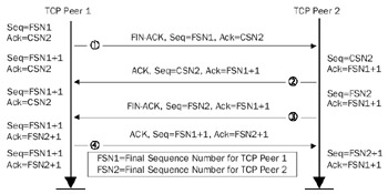
Figure 13-5: A TCP connection termination showing the exchange of four TCP segments.
Typical TCP connection termination processes consist of the exchange of four TCP segments.
Segment 1 The FIN ACK from TCP Peer 1
A TCP peer (TCP Peer 1) that wants to terminate outbound data flow sends a TCP segment that contains no data with the following:
- The Sequence Number field set to the current sequence number for outbound data. When closing the connection, the current sequence number is the final sequence number for outbound data (FSN1 in Figure 13-5).
- The Acknowledgment Number field set to the next byte of inbound data that the TCP peer expects to receive. This number also corresponds to the current sequence number of TCP Peer 2 (CSN2 in Figure 13-5).
- The ACK flag is set, indicating that the Acknowledgment Number field issignificant.
- The FIN flag is set, indicating that no more data will be sent from this TCP peer on the connection.
The following Network Monitor trace (Frame 1 of Capture 13-03, included in the Captures folder on the companion CD-ROM) shows a FIN-ACK segment for an FTP session being closed by an FTP server:
+ ETHERNET: ETYPE = 0x0800 : Protocol = IP: DOD Internet Protocol
+ IP: ID = 0xDFF9; Proto = TCP; Len: 40
 TCP: .A...F, len: 0, seq:1035689055-1035689055, ack:3928116597,
 win:17448, src: 21 (FTP) dst: 1162
 TCP: Source Port = FTP [control]
 TCP: Destination Port = 0x048A
 TCP: Sequence Number = 1035689055 (0x3DBB5C5F)
 TCP: Acknowledgment Number = 3928116597 (0xEA224D75)
 TCP: Data Offset = 20 (0x14)
 TCP: Reserved = 0 (0x0000)
 TCP: Flags = 0x11 : .A...F
 TCP: ..0..... = No urgent data
 TCP: ...1.... = Acknowledgment field significant
 TCP: ....0... = No Push function
 TCP: .....0.. = No Reset
 TCP: ......0. = No Synchronize
 TCP: .......1 = No more data from sender
 TCP: Window = 17448 (0x4428)
 TCP: Checksum = 0x1377
 TCP: Urgent Pointer = 0 (0x0)
Segment 2 The ACK from TCP Peer 2
Similar to the SYN flag, the FIN flag occupies a byte of the TCP sequence space and therefore must be acknowledged as if it were a byte of data. Therefore, the TCP peer receiving the FIN-ACK segment (TCP Peer 2) sends an ACK with the following:
- The Sequence Number field set to the current sequence number for outbound data (CSN2 in Figure 13-5).
- The Acknowledgment Number field set to 1 more than the final sequence number for inbound data on the connection (FSN1 + 1).
- The ACK flag is set, indicating that the Acknowledgment Number field issignificant.
The following Network Monitor trace (Frame 2 of Capture 13-03, included in the Captures folder on the companion CD-ROM) shows an ACK segment sent from the FTP client in response to a FIN-ACK sent by the FTP server:
+ ETHERNET: ETYPE = 0x0800 : Protocol = IP: DOD Internet Protocol
+ IP: ID = 0x291E; Proto = TCP; Len: 40
 TCP: .A...., len: 0, seq:3928116597-3928116597, ack:1035689056,
 win:17234, src: 1162 dst: 21 (FTP)
 TCP: Source Port = 0x048A
 TCP: Destination Port = FTP [control]
 TCP: Sequence Number = 3928116597 (0xEA224D75)
 TCP: Acknowledgment Number = 1035689056 (0x3DBB5C60)
 TCP: Data Offset = 20 (0x14)
 TCP: Reserved = 0 (0x0000)
 TCP: Flags = 0x10 : .A.... TCP: ..0..... = No urgent data
 TCP: ...1.... = Acknowledgment field significant
 TCP: ....0... = No Push function
 TCP: .....0.. = No Reset
 TCP: ......0. = No Synchronize
 TCP: .......0 = No Fin
 TCP: Window = 17234 (0x4352)
 TCP: Checksum = 0x144D
 TCP: Urgent Pointer = 0 (0x0)
Notice how the acknowledgment number is 1 more (1035689056) than the sequence number of the previous FIN-ACK (1035689055), explicitly acknowledging the receipt of the FIN-ACK segment.
Once the FIN is acknowledged, the TCP peer that sent the initial FIN-ACK segment cannot send data (TCP Peer 1). However, only one logical pipe has been terminated. The inbound data pipe for TCP Peer 1 is still open and data can still flow and be acknowledged with ACK segments that contain no data.
Segment 3 The FIN ACK from TCP Peer 2
If the TCP peer with the open outbound data pipe (TCP Peer 2) still has data to send, data can be sent and acknowledged by TCP Peer 1. This is known as a TCP half-close. For example, a TCP half-close occurs when a client application sends the FIN-ACK segment and the server application still has data to send to the client before it can terminate its side of the connection.
Once all outstanding data from TCP Peer 2 is sent and acknowledged, TCP Peer 2 can close its outbound logical pipe to TCP Peer 1. TCP Peer 2 sends a segment with the following:
- The Sequence Number field set to the current sequence number for outbound data. When closing the connection, the current sequence number is the final sequence number for outbound data (FSN2 in Figure 13-5).
- The Acknowledgment Number field set to the next byte of inbound data that the TCP peer expects to receive. In this case, the acknowledgment number is the same as that acknowledged in Segment 2 (FSN1 + 1).
- The ACK flag is set, indicating that the Acknowledgment Number field issignificant.
- The FIN flag is set, indicating that no more data will be sent from this TCP peer on the connection.
The following Network Monitor trace (Frame 3 of Capture 13-03, included in the Captures folder on the companion CD-ROM) shows a FIN-ACK segment for the FTP client closing its outbound pipe:
+ Frame: Base frame properties
+ ETHERNET: ETYPE = 0x0800 : Protocol = IP: DOD Internet Protocol
+ IP: ID = 0x291F; Proto = TCP; Len: 40
 TCP: .A...F, len: 0, seq:3928116597-3928116597, ack:1035689056,
 win:17234, src: 1162 dst: 21 (FTP)
 TCP: Source Port = 0x048A
 TCP: Destination Port = FTP [control]
 TCP: Sequence Number = 3928116597 (0xEA224D75)
 TCP: Acknowledgment Number = 1035689056 (0x3DBB5C60)
 TCP: Data Offset = 20 (0x14)
 TCP: Reserved = 0 (0x0000)
 TCP: Flags = 0x11 : .A...F
 TCP: ..0..... = No urgent data
 TCP: ...1.... = Acknowledgment field significant
 TCP: ....0... = No Push function
 TCP: .....0.. = No Reset
 TCP: ......0. = No Synchronize
 TCP: .......1 = No more data from sender
 TCP: Window = 17234 (0x4352)
 TCP: Checksum = 0x144C
 TCP: Urgent Pointer = 0 (0x0)
Segment 4 The ACK from TCP Peer 1
The FIN flag of Segment 3 occupies a byte of the TCP sequence space and therefore must be acknowledged as a byte of data. Therefore, the TCP peer receiving the FIN-ACK segment (TCP Peer 1) sends an ACK with the following:
- The Sequence Number field set to the current sequence number for outbound data (FSN1 + 1).
- The Acknowledgment Number field set to 1 more than the final sequence number for inbound data on the connection (FSN2 + 1).
- The ACK flag is set, indicating that the Acknowledgment Number field issignificant.
The following Network Monitor trace (Frame 4 of Capture 13-03, included in the Captures folder on the companion CD-ROM) shows an ACK segment that the FTP server sent in response to a FIN-ACK sent by the FTP client:
+ Frame: Base frame properties
+ ETHERNET: ETYPE = 0x0800 : Protocol = IP: DOD Internet Protocol
+ IP: ID = 0xDFFA; Proto = TCP; Len: 40
 TCP: .A...., len: 0, seq:1035689056-1035689056, ack:3928116598,
 win:17448, src: 21 (FTP) dst: 1162
 TCP: Source Port = FTP [control]
 TCP: Destination Port = 0x048A
 TCP: Sequence Number = 1035689056 (0x3DBB5C60)
 TCP: Acknowledgment Number = 3928116598 (0xEA224D76)
 TCP: Data Offset = 20 (0x14)
 TCP: Reserved = 0 (0x0000)
 TCP: Flags = 0x10 : .A....
 TCP: ..0..... = No urgent data
 TCP: ...1.... = Acknowledgment field significant
 TCP: ....0... = No Push function
 TCP: .....0.. = No Reset
 TCP: ......0. = No Synchronize
 TCP: .......0 = No Fin
 TCP: Window = 17448 (0x4428)
 TCP: Checksum = 0x1376
 TCP: Urgent Pointer = 0 (0x0)
Notice how the acknowledgment number is 1 more (3928116598) than the sequence number of the previous FIN-ACK (3928116597), explicitly acknowledging the receipt of the FIN-ACK segment.
TCP Peer 2's outbound pipe is terminated when the ACK segment is received. The TCP connection, with both logical pipes gracefully terminated, is closed.
| Note |
TCP connection terminations do not have to use four segments. In some cases, Segments 2 and 3 are combined. The result is a FIN-ACK/FIN-ACK/ACK sequence. |
TCP Connection Reset
The TCP connection termination process is for the graceful, mutually agreed closure of both pipes of a TCP connection. Both TCP peers exchange FIN segments that are acknowledged explicitly, indicating that all data on each outbound pipe has been sent and acknowledged. Another way to terminate a TCP connection is through a TCP connection reset—a TCP segment with the RST (Reset) flag set.
A TCP connection reset is sent when a parameter problem exists in the TCP header of an inbound TCP segment that cannot be reconciled. For example, an improper source or destination IP address or TCP port number could cause an established connection to be aborted.
Aborting an established TCP connection through a TCP reset also can be intentionally done through Windows Sockets. However, aborting a TCP connection causes the discarding of all TCP data that is either in transit or in buffers waiting to be sent.
A TCP connection reset is used also to reject a TCP connection attempt in response to the receipt of a SYN segment. The most common reason a TCP peer denies a connection attempt with a connection reset is that the destination port in the SYN segment does not correspond to an Application Layer process running at the recipient of the SYN segment. Connection attempts also can be denied when the maximum number of allowed TCP connections is reached. Figure 13-6 shows a TCP connection reset.
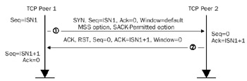
Figure 13-6: A TCP connection reset showing the SYN and RST segments.
| Note |
When a User Datagram Protocol (UDP) message arrives at a destination port that does not correspond to an Application Layer process, an Internet Control Message Protocol (ICMP) Destination Unreachable-Port Unreachable message is sent to the sender of the UDP message. |
The following Network Monitor trace (Capture 13-04, included in the Captures folder on the companion CD-ROM) shows the sequence of packets sent between a host running an FTP client and a host that is not an FTP server. Frame 1 is a SYN segment to the FTP control port; Frame 2 is the connection reset.
Frame 1
+ ETHERNET: ETYPE = 0x0800 : Protocol = IP: DOD Internet Protocol
+ IP: ID = 0x2927; Proto = TCP; Len: 48
 TCP: ....S., len: 0, seq:4065871748-4065871748, ack: 0, win:16384, src: 1164
 dst: 21 (FTP)
 TCP: Source Port = 0x048C
 TCP: Destination Port = FTP [control]
 TCP: Sequence Number = 4065871748 (0xF2584784)
 TCP: Acknowledgment Number = 0 (0x0)
 TCP: Data Offset = 28 (0x1C)
 TCP: Reserved = 0 (0x0000)
 TCP: Flags = 0x02 : ....S.
 TCP: ..0..... = No urgent data
 TCP: ...0.... = Acknowledgment field not significant
 TCP: ....0... = No Push function
 TCP: .....0.. = No Reset
 TCP: ......1. = Synchronize sequence numbers
 TCP: .......0 = No Fin
 TCP: Window = 16384 (0x4000)
 TCP: Checksum = 0x82BE
 TCP: Urgent Pointer = 0 (0x0)
 + TCP: Options
__________________________________________________________________________________

Frame 2
+ ETHERNET: ETYPE = 0x0800 : Protocol = IP: DOD Internet Protocol
+ IP: ID = 0xE18A; Proto = TCP; Len: 40
 TCP: .A.R.., len: 0, seq: 0-0, ack:4065871749, win: 0, src: 21 (FTP)
 dst: 1164
 TCP: Source Port = FTP [control]
 TCP: Destination Port = 0x048C
 TCP: Sequence Number = 0 (0x0)
 TCP: Acknowledgment Number = 4065871749 (0xF2584785)
 TCP: Data Offset = 20 (0x14)
 TCP: Reserved = 0 (0x0000)
 TCP: Flags = 0x14 : .A.R..
 TCP: ..0..... = No urgent data
 TCP: ...1.... = Acknowledgment field significant
 TCP: ....0... = No Push function
 TCP: .....1.. = Reset the connection
 TCP: ......0. = No Synchronize
 TCP: .......0 = No Fin
 TCP: Window = 0 (0x0) TCP: Checksum = 0xEF6E
 TCP: Urgent Pointer = 0 (0x0)
In the connection reset segment:
- The RST and ACK flags are set.
- The sequence number is 0.
- The acknowledgment number is 1 more than the sequence number of the SYN segment (ISN1 + 1). As in the SYN-ACK segment of a connection establish-ment process, the SYN flag occupies a byte of sequence space and is explicitlyacknowledged as if it were a byte of data.
- The window size is 0.
After receipt of a connection reset, the initiating peer can either try again (in practice, three attempts are made) or abandon the connection attempt.
TCP Connection States
A TCP connection exists in one of the states listed in Table 13-1.
|
State |
Description |
|---|---|
|
CLOSED |
No TCP connection exists. |
|
LISTEN |
An Application Layer protocol has issued a passive open and is willing to accept TCP connection attempts. |
|
SYN SENT |
An Application Layer protocol has issued an active open and a SYN segment is sent. |
|
SYN RCVD |
A SYN segment is received and a SYN-ACK is sent. |
|
ESTABLISHED |
The final ACK for the TCP connection establishment process is sent and received. Data can now be transferred in both directions. |
|
FIN WAIT-1 |
The initial FIN-ACK segment to close one side of the connection is sent. |
|
FIN WAIT-2 |
The ACK in response to the initial FIN-ACK is received. |
|
CLOSING |
A FIN-ACK is received but the ACK is not for the FIN-ACK sent. This is known as a simultaneous close, when both TCP peers send FIN-ACKs at the same time. |
|
TIME WAIT |
FIN-ACKs have been sent and acknowledged by both TCP peers and the TCP connection termination process is completed. Once the TIME WAIT state is reached, TCP must wait twice the maximum segment lifetime (MSL) before the connection's TCP port number can be reused. The MSL is the maximum amount of time a TCP segment can exist in an internetwork, and its recommended value is 240 seconds. Thisdelay prevents a new connection's TCP segments using the same port numbers from being confused with duplicated TCP segments of the old connection. |
|
CLOSE WAIT |
A FIN-ACK has been received and a FIN-ACK has been sent. |
|
LAST ACK |
The ACK in response to the FIN-ACK has been received. |
Figure 13-7 shows the states of a TCP connection.
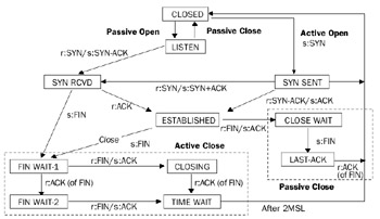
Figure 13-7: The states of a TCP connection.
The connection states that a TCP peer goes through depend on whether the TCP peer is the initiator of the TCP connection establishment or the initiator of the TCP connection termination.
Figure 13-8 shows the connection states of two TCP peers during the connection establishment process.
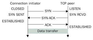
Figure 13-8: The states of a TCP connection during TCP connection establishment.
Figure 13-9 shows the connection states of two TCP peers during the connection termination process.
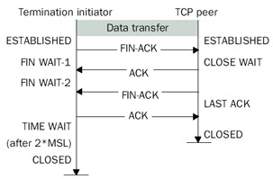
Figure 13-9: The states of a TCP connection during TCP connection termination.
Controlling TCP Connection Terminations in the Windows Server 2003 Family and Windows XP
The TIME WAIT state is used to delay the reuse of the same parameters for a TCP connection, ensuring that duplicates of the old connection's TCP segments in transit are not confused with a new connection's TCP segments. The RFC 793 recommended value for the MSL is two minutes. Therefore, the time that the TCP connection is in the TIME WAIT state is four minutes (2*MSL).
TCP connections in the TIME WAIT state are controlled by the following registry settings:
TcpTimedWaitDelay
Location:
HKEY_LOCAL_MACHINESYSTEMCurrentControlSetServicesTcpipParameters
Data type: REG_DWORD
Valid range: 30-300
Default value: 240
Present by default: No
The value of TcpTimedWaitDelay is the number of seconds that a TCP connectionremains in the TIME WAIT state. The default is the RFC 793 recommended value of 240 seconds (four minutes).
MaxFreeTWTcbs
Location:
HKEY_LOCAL_MACHINESYSTEMCurrentControlSetServicesTcpipParameters
Data type: REG_DWORD
Valid range: 1-0xFFFFFFFF
Default value: 0x3E8 (1000)
Present by default: No
The value of the MaxFreeTWTcbs is the number of TCP connections allowed in the TIME WAIT state. If the number of TCP connections in the TIME WAIT state exceeds this value, the oldest TCP connection is immediately released.
The default values for TcpTimedWaitDelay and MaxFreeTWTcbs work well for many situations. However, for some situations that require the opening and closing of many outbound connections in a short amount of time, the large delay before a TCP port number can be reused can result in the use of all possible TCP ports. Once this state of fullcapacity is reached, new TCP connections cannot be made until existing TCP connections go from the TIME WAIT state to the CLOSED state.
There are three methods that can prevent this problem from occurring:
- Set the value of TcpTimedWaitDelay to a lower value to free TCP port numbers more quickly. The TcpTimedWaitDelay can be set as low as 30 seconds.
- Set the value of MaxFreeTWTcbs to a lower value to force the freeing of TCP connections in the TIME WAIT state more quickly.
- Set the value of MaxUserPort to a higher value. MaxUserPort specifies the maximum port number that can be used when an application requests an available port using Windows Sockets. The default value of MaxUserPort is 5000. Dynamically allocated ports start at 1024. Therefore, with the default setting of 5000, only 3977 dynamic TCP ports are available. In a high-traffic, high-use environment such as a proxy server on the Internet, it is possible to have 3977 TCP ports in either an established or TIME WAIT state. Setting this value higher allows more TCP ports to be in use simultaneously.
Summary
TCP connections are created through the TCP connection establishment process, where two TCP peers exchange SYN segments and determine starting sequence numbers, window sizes, maximum segment sizes, and other TCP options. TCP connections can be maintained through the exchange of periodic keepalive segments, although this is not common. To terminate a TCP connection gracefully, each TCP peer must send a FIN segment and have it acknowledged. A TCP connection reset segment is used to either abort a current connection or refuse a connection attempt.
Part I - The Network Interface Layer
- Local Area Network (LAN) Technologies
- Wide Area Network (WAN) Technologies
- Address Resolution Protocol (ARP)
- Point-to-Point Protocol (PPP)
Part II - Internet Layer Protocols
- Internet Protocol (IP) Basics
- Internet Protocol (IP) Addressing
- Internet Protocol (IP) Routing
- Internet Control Message Protocol (ICMP)
- Internet Group Management Protocol (IGMP)
- Internet Protocol Version 6 (IPv6)
Part III - Transport Layer Protocols
- User Datagram Protocol
- Transmission Control Protocol (TCP) Basics
- Transmission Control Protocol (TCP) Connections
- Transmission Control Protocol (TCP) Data Flow
- Transmission Control Protocol (TCP) Retransmission and Time-Out
Part IV - Application Layer Protocols and Services
- Dynamic Host Configuration Protocol (DHCP) Server Service
- Domain Name System (DNS)
- Windows Internet Name Service (WINS)
- File and Printer Sharing
- RADIUS and Internet Authentication Service
- Internet Information Services (IIS) and the Internet Protocols
- Internet Protocol Security (IPSec)
- Virtual Private Networks (VPNs)
EAN: N/A
Pages: 216
