Internet Protocol (IP) Basics
To fully grasp TCP/IP, one needs to have a thorough understanding of one of its most important protocols: IP. IP is the internetworking building block of all the other protocols at the Internet Layer and above.
Introduction to IP
IP embodies the Internet Layer of the Department of Defense (DoD) Advanced Research Projects Agency (DARPA) model and provides the internetworking functionality that makes possible large-scale internetworks such as the Internet. IP has lasted since it was formalized in 1981, and will continue to be used on the Internet for years to come. Only relatively recently have IP's shortcomings been addressed in a new version known as IP version 6 (IPv6). For more information on IPv6, see Chapter 10, "Internet Protocol Version 6 (IPv6)." IP's amazing longevity is a tribute to its original design.
| More Info |
RFC 791, "Internet Protocol," describes IP. This RFC can be found in the Rfc folder on the companion CD-ROM. |
| Note |
This chapter uses the term IP to refer to version 4 of IP, which is in widespread use today. IP version 6 is denoted as IPv6. |
IP Services
IP offers the following services to upper layer protocols:
- Internetworking protocolIP is an internetworking protocol, also known as a routable protocol. The IP header contains information necessary for routing the packet, including source and destination IP addresses. An IP address is composed of two components: a network address and a node address. Internetwork delivery, or routing, is possible because of the existence of a destination network address. IP allows the creation of an IP internetwork, which consists of two or more networks interconnected by IP router(s).
The IP header also contains a link count, which is used to limit the number of links on which the packet can travel before being discarded.
- Multiple client protocolsIP is an internetwork carrier for upper layer protocols. IP can carry several different upper layer protocols, but each IP packet can contain data from only one upper layer protocol at a time. Because each packet can carry one of several protocols, there must be a way to indicate the upper layer protocol of the packet payload so that it can be forwarded to the appropriate upper layer protocol at the destination. Both the client and the server always use the same protocol for a given exchange of data. Therefore, the packet does not need to indicate separate source and destination protocols.
Examples of upper layer protocols include other Internet Layer protocols such as Internet Control Message Protocol (ICMP) and Internet Group Management Protocol (IGMP) and Transport Layer protocols such as TCP and User Datagram Protocol (UDP).
- Datagram deliveryIP is a datagram protocol that provides a connectionless, unreliable delivery service for upper layer protocols. Connectionless means that no handshaking occurs between IP nodes prior to sending data, and no logical connection is created or maintained at the Internet Layer. Unreliable means that IP sends a packet without sequencing and without an acknowledgment that the destination was reached. IP makes a best effort to deliver packets to the next hop or the final destination. End-to-end reliability is the responsibility of upper layer protocols such as TCP.
- Independence from Network Interface LayerAt the Internet Layer, IP is designed to be independent of the network technology present at the Network Interface Layer. IP is independent of Open Systems Interconnection (OSI) Physical Layer attributes such as cabling, signaling, and bit rate. It also is independent of OSI Data Link Layer attributes such as media access control (MAC) scheme, addressing, and maximum frame size. IP uses a 32-bit address that is independent of the addressing scheme used at the Network Interface Layer.
- Fragmentation and reassemblyTo support the maximum frame sizes of different Network Interface Layer technologies, IP allows for the fragmentation of a payload when forwarding onto a link that has a lower maximum transmission unit (MTU) than the IP datagram size. Routers or sending hosts fragment an IP payload, and fragmentation can occur multiple times. The destination host then reassembles the fragments into the originally sent IP payload. More information on fragmentation and reassembly are provided later in this chapter in the section entitled "Fragmentation."
- Extensible through IP optionsWhen features are required that are not available using the standard IP header, IP options can be used. IP options are appended to the standard IP header and provide custom functionality, such as the ability to specify a path that an IP datagram follows through the IP internetwork.
- Datagram packet-switching technologyIP is an example of a datagram packet-switching technology: Each packet is a datagram, an unacknowledged and nonsequenced message that is forwarded by the switches of the switching network using a globally significant address. In the case of IP, each switch in the switching network is an IP router, and the globally significant address is the destination IP address. This address is examined at each router, which makes an independent routing decision and forwards the packet. Because each router decides independently where to forward a packet, a packet's path from Node 1 to Node 2 is not necessarily a packet's path from Node 2 to Node 1. Additionally, because each packet is separately switched, each can take a different path between the source and destination; because of various transit delays, each packet can arrive in a different order from which it was sent.
Note The term switch is used here for a generalized forwarding device and is not meant to imply a Layer 2 switch. A Layer 2 switch is typically used in Ethernet environments to segment traffic.
IP MTU
Each Network Interface Layer technology imposes a maximum-sized frame that can be sent. This frame consists of the framing header and trailer and a payload. The maximum size of a frame for a given Network Interface Layer technology is called the MTU. For an IP packet, the Network Interface Layer payload is an IP datagram. Therefore, the maximum-sized payload becomes the maximum-sized IP datagram. This is known as the IP MTU.
Table 5-1 lists the IP MTUs for the various Network Interface Layer technologies that are described in Chapter 1, "Local Area Network (LAN) Technologies," and Chapter 2, "Wide Area Network (WAN) Technologies."
|
Network Interface Layer Technology |
IP MTU |
|---|---|
|
Ethernet (Ethernet II encapsulation) |
1500 |
|
Ethernet (IEEE 802.3 Sub-Network Access Protocol [SNAP] encapsulation) |
1492 |
|
Token Ring (4 and 16 Mbps) |
Varies based on token holding time |
|
Fiber Distributed Data Interface (FDDI) |
4352 |
|
X.25 |
1600 |
|
Frame relay |
1592 (with a 2-byte Address field in the Frame Relay header) |
|
Asynchronous Transfer Mode(ATM; Classical IP over ATM) |
9180 |
In an environment with mixed Network Interface Layer protocols, fragmentation can occur when crossing a router from a link with a higher IP MTU to a link with a lower IP MTU. IP fragmentation is discussed in more detail later in this chapter in the section entitled "Fragmentation."
In the Microsoft Windows Server 2003 family, it is possible to override the MTU as reported to the Network Driver Interface Specification (NDIS) interface by the network adapter driver using the following registry setting:
MTU
Key: HKEY_LOCAL_MACHINESYSTEMCurrentControlSetServicesTcpip
ParametersInterfaceGUID
Data type: REG_DWORD
Valid range: 88 -
Default: 0xFFFFFFFF (the MTU reported by the network adapter)
Present by default: No
When TCP/IP initializes, it queries its bound NDIS network adapter driver and receives the MTU. The MTU registry setting is used to set an MTU that is lower than the default MTU, as reported by the NDIS driver, and greater than the minimum value of 88. Values in the MTU registry setting that are greater than the default MTU are ignored; if the MTU registry setting is set to a value less than 88, 88 is used.
It is useful to change the default MTU size for testing or for solving MTU issues in translational bridge environments.
The IP Datagram
An IP datagram consists of an IP header and an IP payload, as shown in Figure 5-1 and described here:
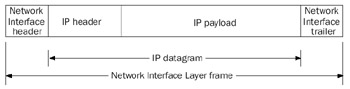
Figure 5-1: The IP datagram.
- IP headerThe IP header is of variable size, between 20 and 60 bytes, in 4-byte increments. It provides routing support, payload identification, IP header and datagram size indication, fragmentation support, and options.
- IP payloadThe IP payload is of variable size, ranging from 8 bytes (a 68-byte IP datagram with a 60-byte IP header) to 65,515 bytes (a 65,535-byte IP datagram with a 20-byte header).
As sent on a link, the IP datagram is wrapped with a Network Interface Layer header and trailer to create a Network Interface Layer frame.
The IP Header
Figure 5-2 shows the IP header's structure. The following sections discuss the fields of the IP header.
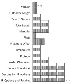
Figure 5-2: The structure of the IP header.
Version
The Version field is 4 bits long and is used to indicate the IP header version. A 4-bit field can have values from 0 through 15. The standard IP version used today on corporate networks and the Internet is version 4. The next version of IP is IPv6. All other values for the Version field are either undefined or not in use. For the latest list of the defined values of the IP Version field, see http://www.iana.org/assignments/version-numbers.
Header Length
The Header Length field is 4 bits long and is used to indicate the IP header size. The maximum number that can be represented with 4 bits is 15. Therefore, the Header Length field cannot possibly be a byte counter. Rather, the Header Length field indicates the number of 32-bit words (4-byte blocks) in the IP header. The typical IP header does not contain any options and is 20 bytes long. The smallest possible header length is 5 (0x5). With the maximum amount of IP options, the largest IP header can be 60 bytes long, indicated with a header length of 15 (0xF).
Using a 4-byte block counter to indicate the IP header size means that the IP header size must always be a multiple of 4. If IP options extend the IP header, they must do so in 4-byteincrements. If an IP option is not 4 bytes long, option padding bytes must be used so that the IP header is always on a 4-byte boundary.
Type Of Service
The Type Of Service (TOS) field is 8 bits long and is used to indicate the quality of service with which this datagram is to be delivered by the internetwork routers. The TOS field has two definitions: the RFC 791 definition and the RFC 2474 definition.
RFC 791 Definition of the TOS Field
As defined in RFC 791, the TOS field contains subfields and flags to indicate desired precedence, delay, throughput, reliability, and cost characteristics.
Within the 8 bits of the TOS field, there are five fields that indicate a different quality of the datagram delivery, as shown in Figure 5-3. The TOS field is set by the sending host and is not modified by routers. All IP datagram fragments contain the same TOS setting as the original IP datagram.
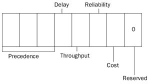
Figure 5-3: The structure of the RFC 791 IP Type Of Service field.
Normally, a sending host sends an IP datagram with the TOS field set to the value of 0x00: routine precedence, normal delay, normal throughput, normal reliability, and normal cost. Routers normally ignore the values in the TOS field and forward all datagrams as if the fields are not set. This is known as TOS0 routing. However, modern routing protocols such as Open Shortest Path First (OSPF) and Integrated Intermediate System-Intermediate System (IS-IS) now support the calculation of routes for each value of the TOS field.
The routers and the routing protocol determine how the various values in the TOS field are interpreted. In a properly configured network, packets with specific TOS values are forwarded over different paths. This can improve routing and delivery efficiency in a multipath IP internetwork. For example, an IP internetwork could have one path for general traffic, one for low-delay traffic, and another path for high-reliability traffic. When sending hosts set various combinations of TOS values, routers can choose among those paths.
The TOS field is used for quality of service (QoS) in IP internetworks.
Precedence
The Precedence field is 3 bits long and is used to indicate the importance of the datagram. Table 5-2 lists the defined values of the Precedence field.
|
Precedence Value |
Precedence |
|---|---|
|
000 |
Routine |
|
001 |
Priority |
|
010 |
Immediate |
|
011 |
Flash |
|
100 |
Flash Override |
|
101 |
CRITIC/ECP |
|
110 |
Internetwork Control |
|
111 |
Network Control |
The Precedence field is set to 000 (Routine) by default.
Delay
The Delay field is a flag indicating either Normal Delay (when set to 0) or Low Delay (when set to 1). If Delay is set to 1, the IP router forwards the IP datagram along the path that has the lowest delay characteristics. An application can request the low delay path when sending either time-sensitive data, such as digitized voice or video, or interactive traffic, such as Telnet sessions. Based on the Delay flag, the router might choose the lower delay terrestrial wide area network (WAN) link over the higher delay satellite link, even if the satellite link has a higher bandwidth.
Throughput
The Throughput field is a flag indicating either Normal Throughput (when set to 0) or High Throughput (when set to 1). If the Throughput field is set to 1, the IP router forwards the IP datagram along the path that has the highest throughput characteristics. An application can request the high throughput path when sending bulk data. Based on the Throughput flag, the router can choose the higher throughput satellite link over the lower throughput terrestrial WAN link, even if the terrestrial link has a lower delay.
Reliability
The Reliability field is a flag indicating either Normal Reliability (when set to 0) or High Reliability (when set to 1). During periods of congestion at an IP router, the Reliability field is used to decide which IP datagrams to discard first. If the Reliability field is set to 1, the IP router discards these datagrams last. An application can request the high reliability path when sending time-sensitive data, so that it cannot be discarded. For example, with some methods of sending digital video, the digitized video is sent as two types of packets: The primary type is used to reconstruct the basic video image, and a secondary type is used to provide a higher resolution image. In this case, the primary packets are sent with the Reliability field set to 1 and the secondary packets are sent with the Reliability field set to 0. If congestion occurs at the router, the router discards the secondary packets first.
Cost
The Cost field is a flag indicating either Normal Cost (when set to 0) or Low Cost (when set to 1), where cost indicates monetary cost. If the Cost field is set to 1, the IP router forwards the IP datagram along the path that has the lowest cost characteristics. An application can request the low cost path when sending noncritical data. Based on the Cost flag, the router can choose a lower cost terrestrial link over a higher cost satellite link, even if the terrestrial link has a lower bandwidth.
Reserved
The Reserved field is the last bit and must be set to 0. Routers ignore this field when forwarding IP datagrams.
Setting the TOS with Ping
The Windows Server 2003 family Ping utility with the -v option can be used to set the TOS value in ICMP Echo messages. The syntax is as follows:
PING -v TOS_Value destination
The TOS value is expressed in decimal format. For example, to ping 10.0.0.1 with a TOS field that is normal precedence, minimum delay, and minimum monetary cost, use the following command:
ping -v 18 10.0.0.1
The Ping -v option has an effect only if the DisableUserTOSSetting registry setting is set to 0.
RFC 2474 Definition of the TOS Field
To accommodate QoS delivery of IP packets over an IP internetwork, RFC 2474 redefines the 8 bits in the TOS field in terms of a 6-bit Differentiated Services Code Point (DSCP) field and 2 unused bits. The DSCP value identifies the per-hop behavior that the receiving routers use to determine the special delivery handling for the packet. DSCP values are defined by network policy.
The RFC 2474–defined TOS field is shown in Figure 5-4.
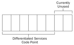
Figure 5-4: The structure of the RFC 2474 IP TOS field.
Differentiated services are an alternative to IP QoS mechanisms that use the Resource ReSerVation Protocol (RSVP). RSVP requires a signaling process initiated by communicating nodes and that flow state be maintained at each intermediate router. With differentiated services, network policy determines the DSCP values and their corresponding delivery and queuing parameters. The network policy is propagated to both the routers and the communicating hosts. When a host needs a nondefault QoS delivery for a packet, it selects the appropriate DSCP value and places it in the TOS field in the IP header. The intermediate routers note the DSCP value and provide the corresponding nondefault QoS delivery service.
TCP/IP for the Windows Server 2003 family uses the RFC 2474 definition of the TOS field by default. Its value is set with the QoS components of the Windows Server 2003 family. You can permit applications to directly modify the TOS field with the following registry setting:
DisableUserTOSSetting
Key: HKEY_LOCAL_MACHINESYSTEMCurrentControlSetServicesTcpipParameters
Value type: REG_DWORD
Valid range: 0 - 1
Default: 1
Present by default: No
The DisableUserTOSSetting controls whether the TOS field can (when set to 0) or cannot (when set to 1) be specified by applications using Windows Sockets registry setting. By default, the TOS field cannot be specified by applications and is used exclusively for IP differentiated services QoS. If QoS is not being used and you want to specify the TOS field value using applications, set DisableUserTOSSetting to 0.
Total Length
The Total Length field is 2 bytes long and is used to indicate the size of the IP datagram (IP header and IP payload) in bytes. With 16 bits, the maximum total length that can be indicated is 65,535 bytes. For maximum-sized IP datagrams, the total length is the same as the IP MTU for that Network Interface Layer technology.
Between the header length and the total length, the IP payload length can be determined from the following formula:
IP payload length (bytes) = total length (bytes) – 4 header length (32-bit words)
Identification
The Identification field is 2 bytes long and is used to identify a specific IP packet sent between a source and destination node. The sending host sets the field's value, and the field is incremented for successive IP datagrams. The Identification field is used to identify the fragments of an original IP datagram.
Flags
The Flags field is 3 bits long and contains two flags for fragmentation. One flag is used to indicate whether the IP payload is eligible for fragmentation, and the other indicates whether or not there are more fragments to follow for this fragmented IP datagram.
More information on these flags and their uses can be found in the section entitled "Fragmentation," later in this chapter.
Fragment Offset
The Fragment Offset field is 13 bits long and is used to indicate the offset of where this fragment begins relative to the original unfragmented IP payload.
More information on the Fragment Offset field can be found in the section entitled "Fragmentation," later in this chapter.
Time To Live
The Time To Live (TTL) field is 1 byte long and is used to indicate how many links on which this IP datagram can travel before an IP router discards it. The TTL field was originally intended for use as a time counter, to indicate the number of seconds that the IP datagram could exist on the Internet. An IP router was intended to keep track of the time that it received the IP datagram and the time that it forwarded the IP datagram. The TTL was then decreased by the number of seconds that the packet resided at the router.
However, the latest modern standard (RFC 1812) specifies that IP routers decrement the TTL by 1 when forwarding an IP datagram. Therefore, the TTL is an inverse link count. The sending host sets the initial TTL, which acts as a maximum link count. The maximum value limits the number of links on which the datagram can travel and prevents a datagram from indefinitely looping.
Some additional aspects of the TTL field include the following:
- Routers decrement the TTL in received packets to be routed before consulting the routing table. If the TTL is less than 1, the packet is discarded and an ICMP Time Expired-TTL Expired In Transit message is sent back to the sending host.
- Destination hosts do not check the TTL field.
- Sending hosts must send IP datagrams with a TTL greater than 0. The exact value of the TTL for sent IP datagrams is either an operating system default or is specified by the application. The maximum value of the TTL is 255.
- A recommended value of the TTL is twice the diameter of your internetwork. The diameter is the number of links between the farthest two nodes on the IP internetwork.
- The TTL is independent of routing protocol metrics such as the Routing Information Protocol (RIP) hop count and the OSPF cost.
Note The TTL can be mistakenly referred to as a hop count when in fact it is a link count. The difference is subtle but important. The hop count is the number of routers to cross to reach a given destination. Link count is the number of Network Interface Layer links to cross to reach a given destination. The difference between hop count and link count is 1. For example, if Host A and Host B are separated by five routers, the hop count is 5, but the link count is 6. An IP datagram sent from Host A to Host B with a TTL of 5 is discarded by the fifth router. An IP datagram sent from Host A to Host B with a TTL of 6 will arrive at Host B.
You can change the default value of the TTL field for sent packets with the following registry setting:
DefaultTTL
Key: HKEY_LOCAL_MACHINESYSTEMCurrentControlSetServicesTcpipParameters
Value type: REG_DWORD
Valid range: 0 - 255
Default: 128
Present by default: No
The default value of DefaultTTL is set to 128 so that IP packets sent by a Windows Server 2003 family–based computer can reach locations on the Internet that might need to traverse many links. Changing the value of DefaultTTL is necessary only when the diameter of your network changes. Windows Sockets applications can override this default value.
Setting the TTL with Ping
The Windows Server 2003 family Ping utility with the -i option can be used to set the TTL value in ICMP Echo messages. The syntax is:
PING -i TTL_Value destination
The TTL value is expressed in decimal format. For example, to ping 10.0.0.1 with a TTL field that is set to 7, use the following command:
ping -i 7 10.0.0.1
The default TTL for ICMP Echo messages sent by Ping is 128.
Protocol
The Protocol field is 1 byte long and is used to indicate the upper layer protocol contained within the IP payload. The Protocol field is an explicit indication of the client protocol. Some common values of the IP Protocol field are 1 for ICMP, 6 for TCP, and 17 (0x11) for UDP. The Protocol field acts as a multiplex identifier so that the payload can be passed to the proper upper layer protocol on receipt at the destination node.
Windows Sockets applications can refer to protocols by name. Protocol names are resolved to protocol numbers through the Protocol file stored in the %SystemRoot% System32DriversEtc directory.
Table 5-3 lists some of the values of the IP Protocol field for protocols that the Windows Server 2003 family supports.
|
Value |
Protocol |
|---|---|
|
1 |
ICMP |
|
2 |
IGMP |
|
4 |
IP in IP encapsulation |
|
6 |
TCP |
|
17 |
UDP |
|
41 |
IPv6 |
|
47 |
Generic Routing Encapsulation (GRE) |
|
50 |
IP Security Encapsulating Security Payload (ESP) |
|
51 |
IP Security Authentication Header (AH) |
|
89 |
OSPF |
For a complete list of IP Protocol field values, see http://www.iana.org/assignments/protocol-numbers.
Header Checksum
The Header Checksum field is 2 bytes long and performs a bit-level integrity check on the IP header only. The IP payload is not included, and IP payloads must include their own checksums to check for bit-level integrity. The sending host performs an initial checksum in the sent IP datagram. Each router in the path between the source and destination verifies the Header Checksum field before processing the packet. If the verification fails, the router silently discards the IP datagram.
Because each router in the path between the source and destination decrements the TTL, the header checksum changes at each router.
To compute the header checksum, each 16-bit quantity in the IP header is ones complemented; bits within the 16-bit quantity that are set to 0 are changed to 1, bits within the 16-bit quantity that are set to 1 are changed to 0. The ones complemented 16-bit quantities are added together and the sum is ones complemented. The result is placed in the Header Checksum field.
For the purposes of computing the header checksum over all the fields in the IP header, the value of the Header Checksum field is set to 0.
Source Address
The Source Address field is 4 bytes long and contains the IP address of the source host, unless a Network Address Translator (NAT) is translating the IP datagram. A NAT is used to translate between public and private addresses when connecting to the Internet.
| More Info |
For more information on NAT, see RFC 1631 in the Rfc folder on the companion CD-ROM. |
Destination Address
The Destination Address field is 4 bytes long and contains the IP address of the destination host, unless the IP datagram is being translated by a NAT or being loose or strict source routed. More information on IP source routing can be found in the section entitled "IP Options," later in this chapter.
Options and Padding
Options and padding can be added to the IP header, but must be done in 4-byte increments so that the size of the IP header can be indicated using the Header Length field.
The following Network Monitor trace (Capture 05-01 in the Captures folder on the companion CD-ROM) shows the structure of the IP header:
+ Frame: Base frame properties
+ ETHERNET: ETYPE = 0x0800 : Protocol = IP: DOD Internet Protocol
 IP: ID = 0x34CD; Proto = ICMP; Len: 60
 IP: Version = 4 (0x4)
 IP: Header Length = 20 (0x14)
 IP: Precedence = Routine
 IP: Type of Service = Normal Service
 IP: Total Length = 60 (0x3C)
 IP: Identification = 13517 (0x34CD)
 IP: Flags Summary = 0 (0x0)
 IP: .......0 = Last fragment in datagram
 IP: ......0. = May fragment datagram if necessary
 IP: Fragment Offset = 0 (0x0) bytes
 IP: Time to Live = 128 (0x80)
 IP: Protocol = ICMP - Internet Control Message
 IP: Checksum = 0xB869
 IP: Source Address = 157.59.8.1
 IP: Destination Address = 157.59.8.1
 IP: Data: Number of data bytes remaining = 40 (0x0028)
+ ICMP: Echo: From 157.59.11.19 To 157.54.08.01
Fragmentation
When a source host or a router must transmit an IP datagram on a link and the MTU of the link is less than the IP datagram's size, the IP datagram must be fragmented. When IP fragmentation occurs, the IP payload is segmented and each segment is sent with its own IP header.
The IP header contains information required to reassemble the original IP payload at the destination host. Because IP is a datagram packet-switching technology and the fragments can arrive in a different order from which they were sent, the fragments must be grouped (using the Identification field), sequenced (using the Fragment Offset field), and delimited (using the More Fragments flag).
Virtual circuit packet-switching technologies such as X.25 and ATM require only fragment/segment delimitation. For example, with ATM Adaptation Layer 5, an IP datagram is segmented into 48-byte segments that become the payloads for ATM cells. ATM sends the stream of cells that comprise the IP datagram and uses the third bit of the Payload Type field in the ATM header to indicate the end of the stream of cells for an IP datagram.
Fragmentation Fields
Figure 5-5 shows the fragmentation fields in the IP header, which are covered in the following sections.
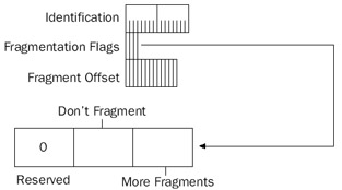
Figure 5-5: The fields in the IP header used for fragmentation.
Identification
The IP Identification field is used to group all the fragments of an original IP datagram together. The sending host sets the value of the Identification field, and this value is not changed during the fragmentation process. The Identification field is set even when fragmentation of the IP payload is not allowed by setting the Don't Fragment (DF) flag.
Don't Fragment Flag
The DF flag is set to 0 to allow fragmentation and set to 1 to prohibit fragmentation, so fragmentation occurs only if the DF flag is set to 0. If fragmentation is needed to forward the IP datagram and the DF flag is set to 1, the router sends an ICMP Destination Unreachable-Fragmentation Needed And DF Set message back to the source host and discards the IP datagram.
Fragmentation and reassembly is an expensive process at the routers and the destination host. The DF flag and the ICMP Destination Unreachable-Fragmentation Needed And DF Set message are the mechanisms by which a sending host discovers the MTU of the path between the source and the destination, or Path MTU Discovery. For more information, see Chapter 8, "Internet Control Message Protocol (ICMP)."
More Fragments Flag
The More Fragments (MF) flag is set to 0 if there are no more fragments that follow this fragment (this is the last fragment), and set to 1 if there are more fragments that follow this fragment (this is not the last fragment).
Fragment Offset
The Fragment Offset field is set to indicate the position of the fragment relative to the original IP payload. The Fragment Offset is an offset used for sequencing during reassembly, putting the incoming fragments in proper order to reconstruct the original payload. The Fragment Offset field is 13 bits long. With a maximum IP payload size of 65,515 bytes (the maximum IP MTU of 65,535 minus a minimum-sized IP header of 20 bytes), the Fragment Offset field cannot possibly indicate a byte offset. At 13 bits, the maximum value is 8191. The fragment offset must be 16 bits long to be a byte offset.
Because 16 bits are required to indicate a maximum-sized IP payload and only 13 bits are available in the Fragment Offset field, each value of the fragment offset must represent 3 bits. Therefore, the Fragment Offset field is defined in terms of 8-byte blocks, called fragment blocks.
During fragmentation, the payload is fragmented along 8-byte boundaries and the maximum number of 8-byte fragment blocks is placed in each fragment. The Fragment Offset field is set to indicate the starting fragment block for the fragment relative to the original IP payload.
For each fragment being fragmented by a router, the original IP header is copied and the following fields are changed:
- Header LengthMight or might not change depending on whether IP options are present and whether the options are copied to all fragments or just the first fragment. IP options are discussed in the section entitled "IP Options," later in this chapter.
- TTLDecremented by 1.
- Total LengthChanged to reflect the new IP header and IP payload size.
- MFSet to 1 for first or middle fragments. Set to 0 for the last fragment.
- Fragment OffsetSet to indicate the position of the fragment in fragment blocks relative to the original unfragmented payload.
- Header ChecksumRecalculated based on the changed fields in the IP header.
The Identification field does not change for each fragment.
Fragmentation Example
As an example of the fragmentation process, a node on a Token Ring network sends a fragmentable IP datagram with the IP Identification field set to 9999 to a node on an Ethernet network, as shown in Figure 5-6.
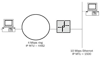
Figure 5-6: An example of a network where IP fragmentation can occur.
Assuming a 9-ms token holding time, a 4-Mbps ring, and no Token Ring source routing header, the IP MTU for the Token Ring network is 4482 bytes. The Ethernet IP MTU is 1500 bytes using Ethernet II encapsulation. Table 5-4 shows the fields relevant to fragmentation in the IP header and their values for the original IP datagram.
|
IP Header Field |
Value |
|---|---|
|
Total Length |
4482 |
|
Identification |
9999 |
|
DF |
0 |
|
MF |
0 |
|
Fragment Offset |
0 |
The IP router connecting the two networks receives the IP datagram, checks its routing table, and notes that the interface on which to forward the datagram has a lower IP MTU than the datagram's size. The router then checks the DF flag. If set to 1, the router discards the IP datagram and sends an ICMP Destination Unreachable-Fragmentation Needed And DF Set message back to the source host. If set to 0, the IP router fragments the 4462-byte IP payload (assuming no IP options are present) into four fragments, each of which can be sent on the 1500-byte Ethernet network.
IP payloads on an Ethernet network can be 1480 bytes long, assuming no IP options are present. Each 1480-byte payload is 185 fragment blocks (185 8 = 1480). Therefore, the four fragments are three fragments each with payloads of 1480 bytes and the last fragment with a payload of 22 bytes (4462 = 1480 + 1480 + 1480 + 22). Figure 5-7 shows the fragmentation process.
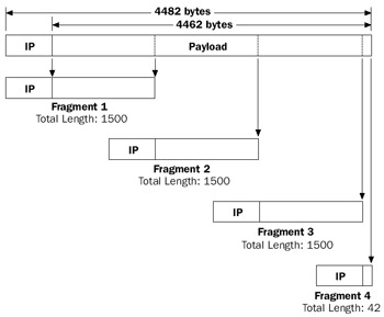
Figure 5-7: The IP fragmentation process when fragmenting from a 4482-byte IP MTU link to a 1500-byte IP MTU link.
Table 5-5 shows the fields relevant to fragmentation in the IP header of the four fragments.
|
IP Header Field |
Value |
|---|---|
|
Fragment 1 |
|
|
Total Length |
1500 |
|
Identification |
9999 |
|
DF |
0 |
|
MF |
1 |
|
Fragment Offset |
0 |
|
Fragment 2 |
|
|
Total Length |
1500 |
|
Identification |
9999 |
|
DF |
0 |
|
MF |
1 |
|
Fragment Offset |
185 |
|
Fragment 3 |
|
|
Total Length |
1500 |
|
Identification |
9999 |
|
DF |
0 |
|
MF |
1 |
|
Fragment Offset |
370 |
|
Fragment 4 |
|
|
Total Length |
42 |
|
Identification |
9999 |
|
DF |
0 |
|
MF |
0 |
|
Fragment Offset |
555 |
Reassembly Example
The fragments are forwarded by the intermediate IP router(s) to the destination host. Because IP is a datagram-based packet-switching technology, the fragments can take different paths to the destination and arrive in a different order from which the fragmenting router forwarded them. IP uses the Identification and Source IP Address fields to group the arriving fragments together.
After receiving a fragment (not necessarily the first fragment of the original IP payload), IP allocates reassembly resources comprised of the following:
- A data buffer to contain the IP payload (65,515 bytes)
- A header buffer to contain the IP header (60 bytes)
- A fragment block bit table (1024 bytes or 8192 bits)
- A total length data variable
- A timer
IP knows that a fragment arrived because either the MF flag or the Fragment Offset field has a nonzero value. An unfragmented IP datagram has the MF flag set to 0 and the Fragment Offset field set to 0. When the first fragment arrives (the Fragment Offset field is 0), its IP header is placed in the header buffer. When the last fragment arrives (the MF flag is 0), the total data length is computed.
For each arriving fragment, the IP payload is placed in the data buffer according to the values of the Fragment Offset and Total Length fields; the bits corresponding to the arriving fragment blocks are set in the fragment block bit table. When the final fragment arrives (which might not be the last fragment), all the bits in the fragment block bit table are set and reassembly of the original IP datagram is complete. IP delivers the IP payload to the appropriate upper layer protocol based on the Protocol field's value.
The reassembly timer is used to abandon the reassembly process within a certain amount of time. If all the fragments do not arrive before the reassembly timer expires, the IP datagram is discarded and the destination host can send an ICMP Time Exceeded- Fragmentation Time Expired message to the source host. RFC 791 recommends a default reassembly timer of 15 seconds; as fragments arrive, the reassembly timer is set to the maximum of the current value and the value of the arriving fragment's TTL field.
Figure 5-8 shows the reassembly process for our example fragmentation.
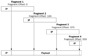
Figure 5-8: The IP reassembly process for the four fragments of the original IP datagram.
Fragmenting a Fragment
It is possible for fragments to become further fragmented. In this case, each fragmented payload is fragmented to fit the MTU of the link onto which it is being forwarded. The process of fragmenting a fragmented payload is slightly different from fragmenting an original IP payload in how the MF flag is set.
When fragmenting a fragmented payload, the MF flag is always set to 1, except when the fragment of the fragmented payload is the last fragment of the original payload.
- If an IP router fragments a previously fragmented first or middle fragment, all of the fragments have the MF flag set to 1.
- If an IP router fragments a previously fragmented last fragment, all of the fragments except the last fragment have the MF flag set to 1.
Therefore, regardless of how many times the IP datagram is fragmented, only one fragment has the MF flag set to 0, indicating the last fragment of the original IP payload.
Network Monitor Capture 05-02 (in the Captures folder on the companion CD-ROM) provides another example of source-based IP fragmentation. The capture is the fragmentation of a 1500-byte IP datagram so that it fits on a subnet with a 576-byte IP MTU.
Avoiding Fragmentation
As seen from the preceding discussion, although fragmentation allows IP nodes to connect regardless of differing MTUs in intermediate network segments and without user intervention, IP fragmentation and reassembly is a relatively expensive process—both at the routers (or sending hosts) and at the destination host. On the modern Internet, fragmentation is highly discouraged; Internet routers are busy enough with the forwarding of IP traffic.
Fragmentation can be avoided by taking the following measures:
- Set the DF flag to 1 on all IP datagrams sent.
- Discover the IP MTU that is supported by all of the links in the path between the source and the destination (the path MTU).
For more information on the Path MTU Discovery process, see Chapter 8, "Internet Control Message Protocol (ICMP)."
Setting the DF Flag with Ping
The Windows Server 2003 family Ping utility with the -f option can be used to set the DF flag to 1 in ICMP Echo messages. The syntax is
ping –f destination
For example, to ping 10.0.0.1 and set the DF to 1, use the following command:
ping -f 10.0.0.1
By default, ICMP Echo messages sent by Ping have the DF flag set to 0 (fragmentation allowed).
Setting the IP Payload Size with Ping
The Windows Server 2003 family Ping utility with the -l option can be used to send IP packets with an arbitrary size by specifying the size of the Optional Data field in an ICMP Echo message. The syntax is:
ping -l Optional_Data_field_size destination
The Optional Data field size value is expressed in decimal format.
For example, to ping 10.0.0.1 with an Optional Data field size of 5000, use the following command:
ping -l 5000 10.0.0.1
The default Optional Data field size for Ping is 32 bytes.
The Optional Data field size is not the same as the IP payload size because ICMP Echo messages include an 8-byte ICMP header. Therefore, to calculate the IP payload's size, add 8 to the size of the ICMP payload. To calculate the IP datagram's size, add 20 to the size of the IP payload. To ping with an Echo message at the maximum size allowed by the Network Interface technology, subtract 28 from the IP MTU. For example, to ping with a maximum-sized Echo message on an Ethernet network (with an IP MTU of 1500), use the following Ping command:
ping -l 1472 10.0.0.1
Using Ping to Create Source-Fragmented Packets
The Windows Server 2003 family Ping utility with the -l option can be used to produce source-fragmented packets. Pinging with an ICMP payload size that is greater than (IP MTU – 28) bytes produces source-fragmented packets. For example, pinging from an Ethernet node with an ICMP payload size of 1472 or less does not produce fragmented packets. Pinging from an Ethernet node with an ICMP payload size greater than 1472 does produce fragmented packets.
Fragmentation and Translational Bridging Environments
Translational bridging is the interconnection of two different Network Interface Layer technologies on the same network by a Layer 2 device such as a bridge or switch. A common use for translational bridges is to connect an Ethernet segment to a Token Ring segment. In modern networks, switches use translational bridging to connect 10-Mbps or 100-Mbps Ethernet nodes to servers on high-speed ports. Common high-speed port technologies include FDDI, Gigabit Ethernet (GbE), and ATM.
The most serious obstacle to translational bridging is the difference in MTU between various Network Interface Layer technologies. Because there is no router involved, we cannot rely on either fragmentation or Path MTU Discovery processes to account for the differing MTUs. A translational bridge does not have the capability to fragment. Frames larger than the MTU of the link onto which they are to be forwarded are silently discarded by the bridge.
As discussed in Chapter 12, "Transmission Control Protocol (TCP) Basics," when a TCP connection is established, both nodes communicate MTU information in the form of the TCP Maximum Segment Size (MSS) option. After receiving each other's TCP MSS, both nodes agree to send TCP segments at the lowest MSS of the two nodes. However, despite this negotiation, proper communication between all nodes in a translational bridging environment might require the modification of the IP MTU of specific nodes.
For example, Figure 5-9 shows two Ethernet switches connected on an Ethernet backbone. On each Ethernet switch is an FDDI port connected to an FDDI ring containing application servers. When the servers on the same FDDI ring communicate with each other, they can send packets with the FDDI MTU of 4352 bytes. When an Ethernet node on one of the switches uses TCP to connect to an application server on either FDDI ring, the TCP MSS option lowers the MTU of TCP-based IP datagrams to 1500.
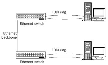
Figure 5-9: An MTU problem in a translational bridging environment caused by two FDDI hosts connected to two Ethernet switches.
However, consider the communication between application servers on different FDDI rings. In creating the TCP connection, each server negotiates an FDDI-based TCP MSS. Therefore, Ethernet switches silently discard TCP-based IP datagrams sent between servers on different rings that have an IP total length greater than 1500.
The solution to this problem is to manually configure the application servers' IP MTU for the smallest IP MTU of all the links within the translational bridged network.
Using our example, the IP MTU of the application servers on the FDDI rings are set to 1500, so translational bridges can forward IP datagrams between FDDI rings. Changing the application servers' MTU means that when sending packets to application servers on the same ring, the packets are sent at the lower MTU of 1500, a lower efficiency than the default FDDI MTU of 4352. However, it is better to have lower efficiency between servers on the same ring than zero efficiency between servers on different rings.
For nodes running a member of the Windows Server 2003 family, use the MTU registry setting to override the default MTU setting reported by NDIS.
IP Options
IP options are additional fields appended to the standard 20-byte IP header. Although IP options are not required on each IP header, the ability to process IP option fields is required. IP options are used infrequently for network testing purposes.
The IP options portion size of the IP header varies in length based on the IP options that are being used. The individual IP options also vary in length from a single octet to multiple four-octet quantities. Recall that the maximum-sized IP header that can be indicated with the Header Length field is 60 bytes. With a standard IP header size of 20 bytes, 40 bytes are left for IP options.
The first byte of each IP option has the format shown in Figure 5-10.
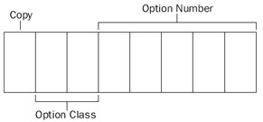
Figure 5-10: The structure of the IP option octet.
Copy
The Copy field is 1 bit long and is used when a router or a sending host must fragment the IP datagram. When the Copy field is set to 0, the IP option should be copied only into the first fragment. When the Copy field is set to 1, the IP option should be copied into all fragments.
Option Class
The Option Class field is 2 bits long and is used to indicate the general class of the option. Table 5-6 lists the defined option classes.
|
Option Class |
Description |
|---|---|
|
0 |
Network control |
|
1 |
Reserved for future use |
|
2 |
Debugging and measurement |
|
3 |
Reserved for future use |
Option Number
The Option Number field is 5 bits long and is used to indicate a specific option within the option class. Each option class can have up to 32 different option numbers.
Table 5-7 lists the defined option classes and numbers for nonmilitary computing.
|
Option Class |
Option Number |
Description |
|---|---|---|
|
0 |
0 |
End Of Option ListA one-octet option used to indicate the end of an option list |
|
0 |
1 |
No OperationA one-octet option used to align octets in a list of options |
|
0 |
3 |
Loose Source RoutingA variable-length option used to route a datagram through a specified path where alternate routes can be taken |
|
0 |
7 |
Record Route A variable-length option used to trace a route through an IP internetwork |
|
0 |
9 |
Strict Source RoutingA variable-length option used to route a datagram through a specified path where alternate routes cannot be taken |
|
0 |
20 |
IP Router AlertA fixed-length option used to inform the router that additional processing of the datagram is required |
|
2 |
4 |
Internet TimestampA variable-length option used to record a series of timestamps at each hop |
End Of Option List
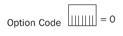
The End Of Option List option is always a single octet in length and is used at the end of the IP options when they do not fall on a 4-byte boundary. This option is used only at the end of all the IP options, not at the end of each option.
No Operation
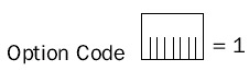
The No Operation option is always a single octet in length and is used between IP options when an IP option does not fall on a 4-byte boundary.
Record Route
The Record Route option is a variable-length option that is used to record the IP addresses of the far side interfaces of IP routers as it traverses the IP internetwork. The far side interface is the interface on the router on which the IP datagram is forwarded, presumed to be farthest from the sending host.
As the IP datagram is forwarded from router to router, each router adds its IP address to the list; each router also modifies the Next Slot Pointer field. The route from the source host to the destination host is recorded. To get the complete route, there must be enough room in the Record Route option header. Unlike Token Ring source routing, the number of IP address slots is specified by the sending host and is fixed in the IP header.
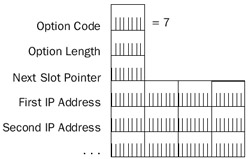
The Record Route option contains the following fields:
- Option CodeSet to 7 (Copy Bit=0, Option Class=0, Option Number=7).
- Option LengthSet by the sending host to the number of octets in the Record Route option.
- Next Slot PointerSet to the octet offset (starting at 1) within the Record Route option of the next available IP address. The minimum value of the Next Slot Pointer field is 4.
- First IP Address, Second IP AddressSet to the IP address of the far side interface by routers. With a maximum of 40 bytes in the IP options portion of the IP header, there is enough room for a maximum of nine IP addresses.
Record Route Processing
An IP router receiving an IP datagram with the Record Route option compares the Option Length and Next Slot Pointer fields. If the Next Slot Pointer field is less than the Option Length field, there are open IP address fields. The router records the IP address of the interface that is forwarding the datagram in the next available IP address field; the router also updates the Next Slot Pointer field by adding 4. If the value of the Next Slot Pointer field is greater than the Option Length field, routers have used all of the available IP address fields. The router then forwards the IP datagram without modifying the Record Route option.
Both hosts must agree that the information in the Record Route option will be processed in IP datagrams sent between them. If one host does not agree, the information in the Record Route option is ignored on receipt and return IP datagrams are not sent with the Record Route option.
Because the Record Route option size is not a multiple of 4 bytes, either an End Of Options option (if there are no more options) or a No Operation option (if there are more options) must be added to ensure that the IP header is an integral multiple of 4 bytes.
Setting the Record Route Option with Ping
The Windows Server 2003 family Ping utility with the -r option can be used to add the Record Route option and set the number of IP address slots in the Record Route option within an ICMP Echo message. The syntax is:
ping -r IP_address_slots destination
The IP address slots value is expressed in decimal format.
For example, to ping 10.0.0.1 with seven IP address slots, use the following command:
ping -r 7 10.0.0.1
When both hosts are computers running a member of the Windows Server 2003 family, the Record Route option records the IP addresses of the far side interfaces of forwarding routers in the ICMP Echo message. When the Echo message is received, the IP addresses recorded are maintained and the Echo Reply message is sent with the same Record Route option. The Echo Reply message contains the recorded route for the Echo message and the recorded route for the Echo Reply message.
Therefore, with the Ping -r option, it is possible to record the far side router inter- faces for the Echo message (the path from Host A to Host B) and the far side router interfaces for the Echo Reply message (the path from Host B to Host A). However, because there is only room for nine IP address slots, this is possible only if there are no more than four routers between hosts.
Network Monitor Capture 05-03 (in the Captures folder on the companion CD-ROM) provides an example of Ping utility traffic and the use of the Record Route option.
| Note |
The Tracert utility does not use the Record Route option. |
Strict and Loose Source Routing
The IP routing process at IP routers is performed through a comparison of the destination IP address with entries in a local routing table. Each router makes a forwarding decision. However, it is sometimes necessary to specify a path that an IP datagram is to take regardless of the router's routing table entries. The path is specified before the source host sends the datagram; this is known as source routing.
For example, in a multipath IP internetwork (where there is more than one path between IP networks), routers choose the best path based on a lowest cost metric. Once a router determines all of the best paths, the higher cost paths are not used unless the topology of the internetwork changes. To check that higher cost paths contain valid links, you must do source routing.
Source routing in IP is done by specifying the IP address(es) of the near side interfaces of the desired routers between the source and its destination. At each leg of the journey, the destination IP address in the IP header is set to the IP address of the next near side router interface. IP supports both loose and strict source routing. In loose source routing, the next router's IP address does not have to be a neighboring router; it can be multiple hops away. In strict source routing, the next router's IP address must be a neighboring router (a single hop away).
IP source routing also records the path taken in the same way as the Record Route option. For each leg of the journey, the IP address of the interface on the router that forwarded the IP datagram is recorded.
| Note |
To use IP source routing, it must be enabled on all the routers in the path between the source and destination hosts. It is a common practice to disable source routing on routers, especially those connected to the Internet. |
Strict Source Route Option
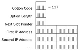
The Strict Source Route option contains the following fields:
- Option CodeSet to 137 (Copy Bit=1, Option Class=0, Option Number=9).
- Option LengthSet by the sending host to the number of octets in the Strict Source Route option.
- Next Slot PointerSet to the octet offset (starting at 1) within the Strict Source Route option for the next router. The Next Slot Pointer field's minimum value is 4. This field is used also in the same manner as the Record Route option to determine the location of the next IP address slot for recording the route.
- First IP Address, Second IP AddressSet by the sending host for the series of IP addresses for successive router destinations in the strict source route; set also by IP routers to the IP address of the forwarding interface. With a maximum of 40 bytes in the IP options portion of the IP header, there is enough room for a maximum of nine IP addresses.
When a sending host sends an IP datagram with the Strict Source Route option, the sending host does the following:
- Sets the Next Slot Pointer field's value to 4.
- Places the first IP address in the strict source route in the IP header's Destination IP Address field.
When an IP router receives an IP datagram with the Strict Source Route option, it compares the Option Length and Next Slot Pointer fields. If the Next Slot Pointer field is less than the Option Length field, the router does the following:
- Adds 4 to the Next Slot Pointer field's value.
- Replaces the IP header's destination IP address with the IP address that is recorded in the next slot (based on the Next Slot Pointer field's new value).
- Records the IP address of the forwarding interface in the previous slot.
If the next destination IP address is not reachable using a directly attached network (the IP address of a neighboring router or host), the IP datagram is discarded and an ICMP Destination Unreachable-Source Route Failed message is sent back to the source host.
If the Next Slot Pointer field's value is greater than the Option Length field's value, the IP datagram has reached its final destination.
Because the size of the Strict Source Route option is not a multiple of 4 bytes, either an End Of Options option (if there are no more options) or a No Operation option (if there are more options after the Strict Source Route option) must be added to ensure that the IP header is an integral multiple of 4 bytes. In the Windows Server 2003 family, TCP/IP places the Strict Source Route option as the last option in the list and uses an End Of Options option to specify the end of the list of options.
Setting the Strict Source Route Option with Ping
The Windows Server 2003 family Ping utility with the -k option can be used to add the Strict Source Route option. The Ping utility also can be used to set the IP addresses of successive routers and the final destination in ICMP Echo messages. The syntax is:
ping -k IP_address_of_first_hop IP_address_of_second_hop …
destination_IP_address
For example, to ping 10.0.0.1 through neighboring router interfaces 192.168.1.1 and 192.168.2.1, use the following command:
ping -k 192.168.1.1 192.168.2.1 10.0.0.1
Network Monitor Capture 05-04 (in the Captures folder on the companion CD-ROM) provides an example of Ping utility traffic and the use of the Strict Source Route option.
Loose Source Route Option
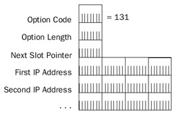
The Loose Source Route option contains the following fields:
- Option CodeSet to 131 (Copy Bit=1, Option Class=0, Option Number=3).
- Option LengthSet by the sending host to the number of octets in the Loose Source Route option.
- Next Slot PointerSet to the octet offset (starting at 1) within the Loose Source Route option for the next router. The Next Slot Pointer field's minimum value is 4. The Next Slot Pointer field also is used in the same manner as the Record Route option to determine the location of the next IP address slot for recording the route.
- First IP Address, Second IP AddressSet by the sending host for the series of IP addresses for successive router destinations in the loose source route, and set by IP routers to the forwarding interface's IP address. With a maximum of 40 bytes in the IP options portion of the IP header, there is enough room for a maximum of nine IP addresses.
When a sending host sends an IP datagram with the Loose Source Route option, the sending host does the following:
- Sets the Next Slot Pointer field's value to 4.
- Places the first IP address in the loose source route in the IP header's Destination IP Address field.
When an IP router receives an IP datagram with the Loose Source Route option, it compares the Option Length and Next Slot Pointer fields. If the Next Slot Pointer field's value is less than the Option Length field's value, the router does the following:
- Adds 4 to the Next Slot Pointer field's value.
- Replaces the IP header's destination IP address with the IP address that is recorded in the next slot (based on the Next Slot Pointer field's new value).
- Records the IP address of the forwarding interface in the previous slot.
If the Next Slot Pointer field's value is greater than the Option Length field's value, the IP datagram has reached its final destination.
Because the size of the Loose Source Route option is not a multiple of 4 bytes, either an End Of Options option (if there are no more options) or a No Operation option (if there are more options) must be added to ensure that the IP header is an integral multiple of 4 bytes.
Setting the Loose Source Route Option with Ping
The Windows Server 2003 family Ping utility with the -j option can be used to add the Loose Source Route option. Additionally, it is used to set the IP addresses of successive routers and the final destination in ICMP Echo messages. The syntax is:
 ping -j IP_address_of_first_hop IP_address_of_second_hop …
destination_IP_address
For example, to ping 10.0.0.1 through neighboring router interfaces 192.168.1.1 and 192.168.2.1, use the following command:
ping -j 192.168.1.1 192.168.2.1 10.0.0.1
Network Monitor Capture 05-05 (in the Captures folder on the companion CD-ROM) provides an example of Ping utility traffic and the use of the Loose Source Route option.
The ability of an IP router running a member of the Windows Server 2003 family to forward source-routed IP packets is controlled by the following registry setting:
DisableIPSourceRouting
Key: HKEY_LOCAL_MACHINESYSTEMCurrentControlSetServicesTcpipParameters
Value type: REG_DWORD
Valid range: 0 - 2
Default: 1
Present by default: No
Use the DisableIPSourceRouting registry setting to forward source-routed packets (when set to 0), to not forward source-routed packets (when set to 1), or to drop all incoming source-routed packets (when set to 2). By default, DisableIPSourceRouting is configured not to forward source-routed packets.
IP Router Alert
The IP Router Alert option is used to indicate to IP routers that additional processing of the IP datagram is required even when the IP datagram is not addressed to the router. The IP Router Alert option is used for RSVP and IGMP version 2. For example, when a router receives an IP datagram with the IP Router Alert option, it looks at the IP Protocol field to see if the IP payload requires additional processing before making a forwarding decision. RFC 2113 describes the IP Router Alert option.
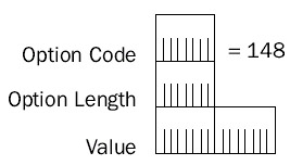
The IP Router Alert option contains the following fields:
- Option CodeSet to 148 (Copy Bit=1, Option Class=0, Option Number=20).
- Option LengthSet to the fixed length of 4.
- ValueA 2-byte field set to 0. All other values are reserved. The value of 0 indicates that the router must examine the packet.
Internet Timestamp
The Internet Timestamp option is used to record the time that an IP datagram arrived at each IP router in the path between the source and destination host. The Internet Timestamp option is similar to the Record Route option in that the sending node creates blank entries in the IP header that routers fill out as the packet travels through the IP internetwork. Each entry consists of the router's IP address and a 32-bit integer timestamp that indicates the number of milliseconds since midnight, Universal Time. If Universal Time is not being used, the high-order bit of the timestamp field is set to 1.
| Note |
To use Internet timestamps, Internet timestamping must be enabled on all the routers in the path between the source and destination hosts. It is common for routers to either not support Internet timestamping or have it disabled. |
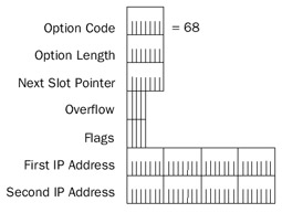
The Internet Timestamp option contains the following fields:
- Option CodeSet to 68 (Copy Bit=0, Option Class=2, Option Number=4).
- Option LengthSet by the sending host to the number of octets in the Internet Timestamp option.
- Next Slot PointerSet to the octet offset (starting at 1) within the Internet Timestamp option of the next slot for the recording of the IP address and timestamp. The Next Slot Pointer field's minimum value is 5.
- OverflowSet by routers to indicate the number of routers that were unable to record their IP address and timestamp.
- FlagsSet by the sending host to indicate the format of the IP Address/Timestamp slots. When Flags is set to 0, the IP address is omitted. This allows up to nine timestamps to be recorded. When Flags is set to 1, the IP address is recorded, allowing up to four IP address/timestamp pairs to be recorded. The Internet Timestamp option format shown assumes Flags is set to 1. When Flags is set to 3, the sending node specifies the IP addresses of successive routers: A timestamp is recorded only if the IP address in the slot matches the router's IP address.
- First IP Address/First Timestamp Set by routers to record the IP address and timestamp of the routers encountered (when Flags is set to 1) or specified (when Flags is set to 3).
When a sending host sends an IP datagram with the Internet Timestamp option, the sending host does the following:
- Sets the Next Slot Pointer field's value to 5.
- For a specified route (when Flags is set to 3), places the series of IP addresses in the Internet Timestamp option.
When an IP router receives an IP datagram with the Internet Timestamp option, it compares the Option Length and Next Slot Pointer fields. If the Next Slot Pointer field's value is less than the Option Length field's value, it does the following:
- If Flags is set to 3, the router replaces the IP header's destination IP address with the IP address that is recorded in the next slot (based on the Next Slot Pointer field).
- If Flags is set to 1 or 3, the router records the IP address of the interface on which the IP datagram was received in the same slot.
- If Flags is set to 0, the router records the timestamp and adds 4 to the Next Slot Pointer field. If Flags is set to 1, the router records the timestamp after the IP address and adds 8 to the Next Slot Pointer field. If Flags is set to 3, the router replaces the IP address and adds 4 to the Next Slot Pointer field.
If the Next Slot Pointer field's value is greater than the Option Length field's value, the router increments the Overflow field. If the Overflow field is 15 before incrementing, an ICMP Parameter Problem is sent back to the source host.
Setting the Internet Timestamp Option with Ping
The Windows Server 2003 family Ping utility and the -s option can be used to send ICMP Echo messages with the Internet timestamp. The syntax is the following:
ping -s slots destination
For example, to ping the IP address of 10.9.1.1 using Internet timestamps with three slots, use the following command:
ping -s 3 10.9.1.1
Network Monitor Capture 05-06 (in the Captures folder on the companion CD-ROM) provides an example of Ping utility traffic and the use of the Internet Timestamp option.
Summary
IP provides the internetworking building block for all other Internet Layer and higher protocols in the TCP/IP suite. IP provides a best effort, unreliable, connectionless datagram delivery service between networks of an IP internetwork. The IP header provides addressing, type of delivery, maximum link count, fragmentation, and checksum services. IP fragmentation provides a way for IP datagrams to travel over links with a lower IP MTU than the original IP datagram. The basic services of the IP header are extended through IP options, the most common of which provide source routing, path recording, router alert, and timestamping functions.
Part I - The Network Interface Layer
- Local Area Network (LAN) Technologies
- Wide Area Network (WAN) Technologies
- Address Resolution Protocol (ARP)
- Point-to-Point Protocol (PPP)
Part II - Internet Layer Protocols
- Internet Protocol (IP) Basics
- Internet Protocol (IP) Addressing
- Internet Protocol (IP) Routing
- Internet Control Message Protocol (ICMP)
- Internet Group Management Protocol (IGMP)
- Internet Protocol Version 6 (IPv6)
Part III - Transport Layer Protocols
- User Datagram Protocol
- Transmission Control Protocol (TCP) Basics
- Transmission Control Protocol (TCP) Connections
- Transmission Control Protocol (TCP) Data Flow
- Transmission Control Protocol (TCP) Retransmission and Time-Out
Part IV - Application Layer Protocols and Services
- Dynamic Host Configuration Protocol (DHCP) Server Service
- Domain Name System (DNS)
- Windows Internet Name Service (WINS)
- File and Printer Sharing
- RADIUS and Internet Authentication Service
- Internet Information Services (IIS) and the Internet Protocols
- Internet Protocol Security (IPSec)
- Virtual Private Networks (VPNs)
EAN: N/A
Pages: 216
