Troubleshooting a Home Network
Troubleshooting a HomeNetwork
In this chapter, you will learn about
- Troubleshooting network connections
- Troubleshooting network cabling
- Troubleshooting a network PC’s configuration
Tracking down a problem on a network is often more of an issue of where to begin looking than it is resolving the problem. Often a network problem is easily remedied once you’re able to pinpoint its source.
Networks, including home networks, bring together several layers of technology—cable, hardware, and software—all capable of causing or contributing to a network or a networked computer not performing properly.
In this chapter, we look at some of the ways you can diagnose and resolve problems on a network, including testing network cabling, a network connection, and a networked computer’s configuration.
Be consistent: list problems then create solution checklists, or list each problem with its own checklist.
Troubleshooting Network Connections
Any number of things can go wrong with network connections, but generally, and especially in a home environment, once they are configured properly and working, network connections tend to continue to work until something is changed on the computer or its network. So, the first thing to check, if the network or a computer develops connection problems, is whether or not anything has changed recently.
Troubleshooting Dialup Connections
If a dialup connection fails to connect, there are five areas to check:
- Phone connections
- Modem problems
- Protocols
- Remote responses
- Telephone company or phone line problems
- Phone connectionIf there is no dial tone present, you should get an error message displayed on the computer to that effect. The sound produced by nearly all modems is there for the user to track the action of the connection (called a handshake, which is the activities involved with two modems negotiating the connection) as it is being made. The first of these sounds is the dial tone from the phone line. If the modem is not connecting and you don’t hear a dial tone, there is likely a problem with the phone service, wall jack, the wire, the RJ-11 connector, or the connection between the connector and the wall jack. Of course, this assumes that you are getting a dial tone on all other phone connections.
- Modem problemsIf the modem is failing to complete the handshake with the modem at the other end and a timeout or connection failed message is displayed on the PC, it is likely that the modem is configured incorrectly in terms of its character length, start and stop bits, and speed. Check with the technical support people at the Internet Service Provider (ISP) to verify what the modem’s settings should be. Depending on the modem, these settings can be made through software on the PC or may have to be made through toggle switches (DIP switches) on the modem. Set the modem configuration as required and retry the connection.
- ProtocolsProtocol problems are common with new modems and typically the modem’s Transmission Control Protocol/Internet Protocol (TCP/IP) or another protocol has not been properly configured. Remember that dialup connections require the Point-to-Point Protocol (PPP). Verify that the proper TCP/IP protocols are enabled and that the proper bindings (protocols linked to one another) are set. If you aren’t sure which protocols or bindings are required, contact the service provider’s technical support for this information.
- Remote responseThe ISP network access server (NAS) to which you are attempting to connect may be down or having problems. The dialer may also be dialing an incorrect number or be configured improperly with other erroneous information. Before making any assumptions about why this may be happening, call the ISP’s technical support people or have the customer call to verify these settings.
- Telephone company or phone line problemsStatic or crosstalk on the telephone line can cause a modem to disconnect frequently and, typically, very soon after completing a connection. Line noise can also cause so many data retransmissions that the connection’s data speed can appear exceptionally slow. Another common problem is call-waiting being active on the modem line because the signaling that is sent to indicate a call is waiting will interrupt the connection. If call-waiting is enabled on a line, you can temporarily suspend it by dialing *70 on the appropriate line before reattempting to dial out through the modem.
Troubleshooting a DSL or Cable Connection
The problems associated with a digital subscriber line (DSL) or cable connection are typically one of a set of common issues. DSL bridges and routers do have a few problems specific to them, just as cable modems have their unique problems. However, for the most part, connection issues for DSL and cable modems are very similar. The next few sections list the more common connection problems for these services and how to resolve them.
Common DSL and Cable Connection Problems
Here are the more common problems a customer could experience with a DSL connection:
- Authentication
- Link control
- Physical connection
- Sync
- AuthenticationIf the connection fails to establish during a startup, the username and password being used to log onto the system or the configuration settings on the computer or Internet gateway may be erroneous. Understand that although DSL (and cable) are “always on” services, should the customer shut down (power off) his computer, then when the computer is powered on, a boot and sign on sequence occurs where these errors may appear.
- Link controlIf the connection link is established and then quickly dropped, the problem is likely one of configuration on the computer. Verify that the computer’s settings match those indicated in the user documentation for the DSL or cable modem. If the computer’s configuration is as it should be, contact the service provider for assistance.
- Physical connectionIf the connection is intermittent, there is something wrong with the physical connection. Verify the connections to the computer and Internet gateway and if they are properly connected, have the customer call the service provider.
- SyncTo work properly, DSL and cable lines must be “in sync,” or in synchronization, which means that the Internet gateway is connected and receiving a signal over the phone or cable line. In other words, the line must have a link established even if no data is being transmitted. Use the owner’s manual for the Internet gateway to determine from the status light-emitting diodes (LEDs) on the device whether or not a link is established and the link is in sync. If the connection is not in sync, power off the computer and then the Internet gateway device. Wait about 30 seconds and then power up the Internet gateway and then the computer. This should establish and sync-up the connection. If the problem persists, contact the service provider’s technical support line.
DSL/Cable Troubleshooting Checklist
Before calling the technical support function or a service provider, here is a list of things to check so that you can be fairly confident of the source and nature of the problem:
- Check the power connection on the Internet gateway device.
- Check the cable/phone line connection on the Internet gateway device for snugness and to ensure that there are no free wires or cuts or breaks in the wiring connecting to the source.
- Check the RJ-45 connection to the computer for snugness, free wires, or cuts or breaks in the patch cord.
- Check the link lights on both the Internet gateway and the network adapter on the computer for activity and sync.
Troubleshooting Wireless Connections
If a computer equipped with a wireless network adapter is having a connection problem, the first step in troubleshooting the problem is to verify that the computer has recognized the wireless network adapter and that the appropriate device driver software has been properly installed. To troubleshoot this problem, follow these steps:
- Hardware checkTo check the network adapter and the device driver software, use the Windows Device Manager. If a red “x” or a yellow “i” icon is displayed next to the wireless network adapter’s name instead of a small icon of a network card, you need to reinstall the network adapter and driver after checking the Hardware Compatibility List (HCL) for the Windows version running on the computer.
- Settings checkIf the network adapter and driver are properly installed, the next thing to check is the computer’s network settings. Use the documentation for the network adapter and the network access point (NAP) to verify the settings for the adapter.
- Signal strength and link quality testThe procedure used to check the signal strength and the link quality varies by manufacturer, so reference the device documentation for the process used for the specific network adapter and NAP in use. If moving the computer closer to the NAP eliminates this problem, this is definitely the issue.
- Renew IP configurationUnder the heading of “if all else fails,” use IPCONFIG to release and renew the Dynamic Host Configuration Protocol (DHCP) settings for the computer (see the following section for instructions on how to do this).
Troubleshooting DHCP Problems
If after booting or restarting a networked PC, no network connection is present, a good place to begin your diagnosis is by running the IPCONFIG command. Figure 14-1 shows a sample of the output produced by this command. Notice the entry for “IP Address.” In Figure 14-1, the IP address is fine, reflecting an address has been assigned to the PC by a DHCP server on the network, either locally or at the ISP.
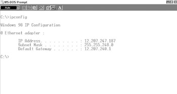
Figure 14-1: The output produced by the IPCONFIG command
Should a networked computer boot up and not find a DHCP server available, the computer will complete its boot cycle by using an Automatic Private IP Addressing (APIPA), which is a nonfunctioning IP address from a range reserved by Microsoft for just this purpose. When this happens, unless the PC requesting an IP address is able to get one, it will continue to poll for an IP address from the DHCP server after waiting increasingly longer wait periods. This process continues until the networked PC finally gets an IP address from a DHCP server.
The address provided by APIPA allows the PC (DHCP client) to automatically configure itself with an IP address from the range of 169.254.0.1 to 169.254.254.255 using a Class B subnet mask of 255.255.0.0. Understand that this IP address is merely a placeholder and cannot be used to access the network.
When a PC is unable to obtain an IP address from the DHCP server, check with the ISP to try to determine why this may be happening. The problem could very well be that the ISP’s DHCP server is down. However, if the ISP indicates that there is no reason for a computer to not be able to get its IP configuration from its DHCP server, you should try releasing and renewing the DHCP “lease” using the following process (on Windows 98, Me, NT, 2000, and XP computers):
- Click on the Start button and choose Run from the Start menu.
- In the Open: box, enter “cmd” (“command” for Windows 98 and Me) and click OK. This will open a command prompt window.
- At the command prompt (C:>), enter ipconfig /release_all and press the Enter key. IPCONFIG will confirm the release with a display showing zeroes in the IP Address and Subnet Mask fields.
- At the command prompt, enter ipconfig /renew_all and press Enter. IPCONFIG should confirm the renewal of the IP configuration data with values in the IP Address, Subnet Mask, and Default Gateway fields.
- At the command prompt, enter exit and press the Enter key to close the command prompt window.
If this process fails to correct the problem, you must re-install the network adapter’s device drivers and reconfigure the network protocols settings. Before retesting the connection, verify the network settings with the ISP’s technical support.
Troubleshooting Network Connections
Another reason a PC may not be automatically configured by the network is that it no longer has a network connection or for some reason the network has stopped communicating with it. There are two TCP/IP utilities that can be used to make an initial diagnosis of this problem.
PING
The first is the PING utility. This command sends out a message that requests that a remote device with a specific IP Address or domain reply with a message (an echo). If this activity succeeds, you know the connection between the two devices is valid. The PING command also times this process. A slow response time could indicate congestion or perhaps a mechanical problem along the way. Figure 14-2 shows the output produced by the PING command.
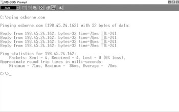
Figure 14-2: The results of a PING command
| Note |
The Domain Name System (DNS) is used to identify the IP Address of the domain name “osborne.com.” This IP Address is then used by the PING command to send its messages. |
However, if the PING command cannot find or doesn’t receive a response from the destination address or domain entered, an error message will indicate that.
TraceRoute
The second command that you can use to determine if there is a path problem between two network devices is the TraceRoute utility. This traces and tracks the path used by a message to reach a remote destination IP Address by displaying each router or internetworking device the message passes through on its journey. The time used for each “hop” is also displayed to help diagnose possible bottlenecks on the network. Figure 14-3 shows the output produced by a TRACERT command.
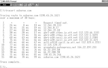
Figure 14-3: The display of the TRACERT command
TraceRoute is implemented on various systems as TRACEROUTE, TRACERT, or TRACE, with TRACERT used on Windows systems. This command displays the complete route from a source IP address to a destination IP address. TRACERT transmits probe packets one at a time to each router or switch on the path between the source and the destination. When an echo is received at the source, the round-trip time for that hop is displayed. TRACERT displays only two different events: the time (called time-to-live or TTL) was exceeded or the destination was unreachable. This information is very helpful in determining if there is a breakdown or bottleneck in a particular route.
Testing Network Wiring
The benefit that comes from planning a network before installing it is that you and the customer both know what to expect when you are done, right? The downside may be that by the same token both you and the customer know what to expect.
The only way you can assure yourself and demonstrate to the customer that the network’s wiring and infrastructure supports the network to be installed on it is with a planned and formal test procedure that incorporates the Transmission Performance Specifications for Field-Testing of Unshielded Twisted-Pair Cabling Systems (TIA/EIA TSB-67 for short) and TSB-95, which provides additional test parameters for Cat 5 wiring.
Cable Certification Testing
A number of handheld devices are available to perform the tests prescribed in these two TSB standards. In fact, a variety of Cat 5 testers are available to perform what is called a certified test. By certifying the cable, the customer is assured that the network wiring is installed to specification and is ready to support any network-capable devices attached to the network. Certifying the cable also provides a benchmark for any future network or cable problems. However, Cat 5 testing devices can be quite expensive. Cable testing units include a master unit and a slave unit, which are attached to the ends of the cable segment being tested, and an auto-test function that measures the results of the test as either a pass or a fail.
Essentially, Cat 5 testing units perform two tests: a link test and a channel test. The link test measures the end-to-end connectivity of a cable segment and is typically run on the cable running from the distribution panel to a wall outlet. A channel test extends the link test to include devices attached to the cable segment.
A Cat 5 link (cable only) should not be more than 295 feet (90 meters) in length. A Cat 5 channel shouldn’t be more than 328 feet (100 meters) in length. A link is a single cable run and a channel is all of the cable and connections between two communicating devices. The difference of 33 feet or 10 meters between a link and a channel represents the cables used to connect a computer or other device to a link. So what this boils down to is that the cable running between a patch panel and a wall jack can only be 90 meters in length and all of the cables used to complete the connection between a computer and a central device (such as a gateway or router) cannot exceed 100 meters in length.
EIA TIA TSB Tests
The Telecommunications Industry Association/ Electronic Industries Alliance (TIA/EIA) TSB standards specify standard cable testing procedures. The standard TSB tests are
- Attenuation testThis test measures the attenuation affect on a signal transmitted on a cable. A series of frequencies up to 100 MHz is transmitted on each wire pair at one end of a link and the strength of the signal received at the other end of the cable is measured.
- Length testAs it sounds, this test measures the length of a cable segment. The test is set up to test both links and channels using what is called time domain reflectometry, or TDR technology. TDR emits a signal pulse and then calculates the length of the cable based on what is called nominal velocity of propagation (NVP). The result of this test is the distance to a reflection point on the cable. On a good cable, the distance displayed should be the length of the actual cable run. However, if there is a problem on the cable, such as a break, kink, short, or the like, the length test will return the distance to that problem.
- Near-end crosstalk test (NEXT)This test places a test signal on one pair of wires and then measures all of the other wire pairs for signal presence to see how much crosstalk the cable is allowing. Crosstalk is electromagnetic signals on one wire being picked up by another wire.
- Wire-map testThis looks at each individual wire in the cable and whether or not it maps to the same pin at each end of the cable. This test is used to identify connector and pinning errors on a cable segment.
Any link that fails one of these tests should be replaced or, in the case of the length test, shortened. If a channel fails, you may need to test the patch cords used to connect the networked device to the link to decide if the problem is in the cable link or patch cords.
Wire testing should be performed in the pre-wire phase of a new construction project and then again before the network devices are attached.
If the network is to use powerline or phone line, any line problems should also be affecting the AC power or the telephone lines. If not, the problem is either with the media adapter or the patch cord used to connect a device to the adapter.
Simple Cable Testing Devices
It isn’t totally necessary in every situation for the cable to be certified. Often, especially as part of a troubleshooting procedure, all that is needed is to a test for signal continuity, assuming the initial installation was properly tested. Whereas cable certification devices can cost thousands of dollars, quality cable testers range in capability from all-in-one devices to continuity testers and most are reasonably priced. For home automation networking, you should consider a multiple media tester, like the one shown in Figure 14-4.
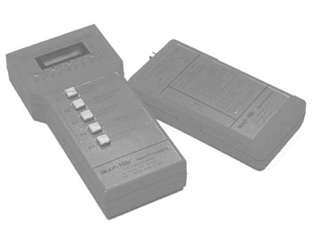
Figure 14-4: A multiple media, multiple function LAN cable tester
Photo courtesy of North Hills Signal Processing.
Configuring Network Computers
In a majority of situations, a network connection problem typically occurs when something has changed on a networked computer. This doesn’t mean that cable, connector, service provider, and Internet gateway problems don’t occur, only that these components of a network continue to work until changes are made.
When I say changes to a network computer, I don’t only mean changes to the computer’s networking configuration or equipment. Changes can include new software, new hardware, and the conflicts they may create. So, the Number 1 troubleshooting step when diagnosing a networked computer for connection problems is to determine if anything, and I mean anything, has changed on the computer and remove it to see if the problem goes away. Then you can deal with the issues being created and solve the larger issue of incompatibility.
Configuring a Windows Computer
When configuring a computer on a home network, you must check the installation of the network adapter and TCP/IP protocols and verify operations.
Checking the Network Adapter
Windows 2000 and XP use Plug-and-Play (PnP) technology to detect and configure an internal network interface card (NIC) installed in a Peripheral Components Interconnect (PCI) slot. However, before you get too far along with connecting a computer to the network, you should verify the NIC’s settings. To do this, use these steps:
- To open the properties window for the NIC, you have two navigation choices:
- Click the Start button and choose Settings from the Start menu and then Network and Dial-up Connections from the Settings menu.
- Right-click the My Network Places icon on the Desktop and choose Network and Dial-up Connections.
Right-click the network connection that is or will be connected to the network to display the properties window for the NIC (see Figure 14-5).
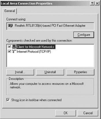
Figure 14-5: The NIC Properties Window on a Windows 2000/XP computer
- In the panel labeled “Components checked are used by this connection,” highlight Internet Protocol (TCP/IP), and then click the Properties button below the panel. The TCP/IP Properties window (see Figure 14-6) will open.
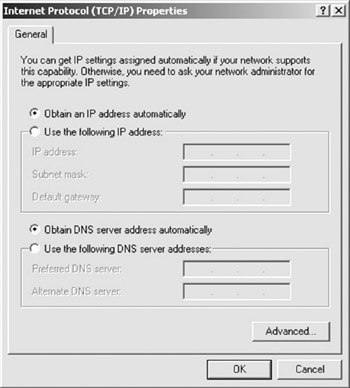
Figure 14-6: The Internet Protocol (TCP/IP) window on a Windows 2000/XP computer. - Verify that the Obtain an IP address and the Obtain DNS server address automatically are selected and if not, change the settings so that they are the only items with their radio buttons (a round option button) selected.
- Click OK on this dialog box and the next window to configure the TCP/IP client. Windows 2000 computers must be restarted to set the configuration, but Windows XP computers don’t require that step. The Windows 2000 computer will be assigned its IP configuration during the startup and the Windows XP computer gets the configuration after a few minutes. Use the IPCONFIG command (see “Troubleshooting DHCP Problems” earlier in the chapter) to verify the settings.
Configuring a Macintosh Computer
To enable a Macintosh computer, one that is running Mac OS 7 or later, use the following steps:
- Open the Apple menu by clicking the apple icon on the top menu bar and choose Control Panels from the menu. From the Control Panels menu, choose TCP/IP, which is located near the bottom of the list. If the system opens a window for Control Panels, choose the TCP/IP icon.
- On the TCP/IP dialog box, set the Connect via choice according to the Internet gateway’s instructions. In most instances, the choice should be Using DHCP Server. Close the window and choose Save on the confirmation box.
- Some Mac systems may need to restart at this point, and a message will be displayed indicating this.
Review
Most computer problems occur immediately after a change is made to the computer’s hardware, software, or configuration.
To diagnose a dialup connection, you should check the following: the phone connection, the modem settings, the protocol configuration on the computer, the service provider’s NAS, and if there are technical issues on the phone line.
To troubleshoot a DSL or cable connection, you should check the following: authentication, link control, the physical connection, and if the system has synchronized (is in sync). To diagnose a connection problem on a DSL or cable connection, check the power connection on the Internet gateway, the phone or cable connection to the Internet gateway, the RJ-45 connection to the computer and the Internet gateway, and the link lights on the Internet gateway and the network adapter, and verify the integrity of all cables.
To troubleshoot a wireless connection, perform a hardware check on the computer using the Device Manager to verify that the network adapter is properly installed and functioning, check the network settings on the computer, test the signal strength and the link quality between the computer and the NAP, and release and renew the IP configuration on the computer.
Many networked computer issues are related to the network configuration on the computer, especially in the DHCP settings. To check these settings, run the IPCONFIG command to display the IP configuration on the computer. A quick way to see if a computer is having DHCP problems is to run IPCONFIG; if the computer is assigned an IP in the range of 169.254.0.1 to 169.254.254.255, the DHCP is not functioning properly.
Two tools that you can use to check a computer’s connection are the PING command to ping the Internet gateway and TRACERT to see if there is a routing issue between the home network and the service provider.
If you suspect the connection problem may be in the network media, you can run the TIA/EIA TSB-67 tests on the cable to check its attenuation, length, NEXT, and wire-mapping. Cable testing devices are generally inexpensive and readily available.
A common source for connection problems on a computer is its network configuration. The newer Windows systems (2000 and XP) virtually auto-configure themselves to a network, but you should check the network adapter’s settings as part of your troubleshooting.
Questions
- Which of the following is not likely the source of a modem connection problem?
- Modem
- Phone line
- Network adapter
- PPP protocol settings
- Which of the following can cause a DSL/cable connection to fail because of username and password issues?
- Authentication
- Synchronization
- Link control
- Bad physical connection
- What is one of the first things you should check to see if a physical connection, link, and sync have been established on a DSL/cable connection?
- Temperature of the patch cord
- Link/activity lights
- Computer’s TCP/IP settings
- Service provider technical help
- Of the following, which troubleshooting step is not performed on a computer using a wireless network adapter to connect to a network?
- Hardware check
- Setting check
- Signal strength and link quality test
- Renew DHCP configuration
- What command can be used to verify the IP configuration on a computer?
- PING
- TRACERT
- IPCONFIG
- DNS
- When a network computer cannot find a DHCP server, what service is used to assign the computer an IP address?
- DNS
- RARP
- BOOTP
- APIPA
- Which TCP/IP command is used to verify the connection between two network devices?
- TRACERT
- DHCP
- PING
- IPCONFIG
- What TCP/IP command is used to determine if a problem exists on the routing path between two network devices?
- TRACERT
- DHCP
- PING
- IPCONFIG
- What is the cable testing standard for Cat 5 wiring?
- EIA/TIA 232
- EIA/TIA 568
- EIA/TIA TSB-67
- IEEE 802.3
- Which is the technology used to check the length of a cable?
- Attenuation
- TDR
- NEXT
- Wire-map
Answers
- C. A modem connects to a computer through its serial port and not a network adapter. The other choices can each contribute to a modem connection problem.
- A. This step verifies the username and password of the link attempting to log into the DSL/cable service provider’s network. The other choices, with the exception of a bad physical connection of course, are aspects of the link established between the Internet gateway and the ISP.
- B. If there are no lights on or flashing on the Internet gateway, then something is seriously wrong with the connection. There could be something wrong with the TCP/IP settings, but the other choices are just silly.
- C. All of the others are performed on the computer.
- C. DNS is used to translate domain names into their IP address equivalents. (See questions 7 and 8 for PING and IPCONFIG.)
- D. This service assigns a temporary IP address that allows the computer to complete its startup. RARP and DNS are used to look up IP addresses, and the computer uses BOOTP to request its DHCP information.
- C. PING sends out an echo request message and if present or connected, the receiving station sends back an echo response.
- A. TRACERT times the connection between each of the routers (hops) located on the path between two network devices.
- C. This standard, along with TSB-95, establishes the testing procedures for Cat 5 wiring.
- B. TDR emits a signal pulse and then calculates the length of the cable based on NVP.
Part I - Home Technology Installation Basics
- Wire and Cable Basics
- Connector Types and Uses
- Wiring Installation Practices
- Codes, Standards, and Safety Practices
Part II - Structured Wiring
- Infrastructure Wiring Basics
- Planning a Structured Wiring Installation
- Rough-In Installation
- Trim-Out Installation
- Troubleshooting Structured Wiring
Part III - Home Computer Networks
- Computer Network Basics
- Computer Network Hardware
- Computer Network Software
- Designing and Installing a Computer Network
- Troubleshooting a Home Network
Part IV - Audio/Video Systems
- Distributed Audio System Basics
- Designing and Installing Distributed Audio Systems
- Distributed Video Basics
- Designing and Installing Distributed Video Systems
- Troubleshooting Audio Systems
- Troubleshooting Video Systems
Part V. Home Lighting Management Systems
- Home Lighting Basics
- Home Lighting Devices
- Designing a Home Lighting Control System
- Installing a Home Lighting Control System
- Troubleshooting and Maintaining Lighting Control Systems
Part VI - Telecommunications
- Home Communication System Basics
- Designing and Installing a Home Telephone System
- Troubleshooting a Home Communication System
Part VII - HVAC and Water Management
Part VIII - Security System Basics
- Security System Basics
- Designing a Home Security System
- Installing a Home Security System
- Troubleshooting and Maintaining a Home Security System
- Home Security Surveillance Systems
- Home Access Control Systems
Part IX - Home Technology Integration
- Defining Users Needs and Desires
- User Interfaces
- Home Automation Controllers
- Programming
- Integrating the Connected Home
- Other Home Technology Integration Devices
Part X - Appendices
EAN: N/A
Pages: 300
