Installing a Home Security System
Installing a HomeSecurity System
In this chapter, you will learn about
- Wiring and installing home security sensors, contacts, and keypads
- Configuring the security system control panel
- Testing a home security system
The activities involved with the installation of a home security system are about the sensors and contacts. In order for the home security system to perform and protect the residence and its occupants, they must be carefully placed to do their job properly. If a window contact doesn’t contact correctly or an opened door blocks a motion sensor, the security system won’t be able to perform as it should and detect an intruder, defeating the purpose of the entire system.
This chapter focuses on the steps used to install and test the sensors, contacts, keypads, and control panel of a home security system. The focus is on installing hard-wired systems, but some information about the installation of a wireless system is included as well.
Video surveillance and home access systems can also be integrated into a home security system and are covered in Chapters 35 and 36, respectively.
A hard-wired security system requires very little after-installation maintenance and provides the assurance that if a sensor or contact trips, the system master or control panel will receive a signal, which may not always be true of a wireless system. However, a wireless security system is easier to install in a retrofit situation, but it also has some placement and operational issues that are discussed later in the chapter.
Component Wiring and Installation
Installing security system components as part of a new construction project allows the cabling required for the sensors, contacts, and keypads to be placed in a room or zone to be installed along with the structured wiring system. However, if the system is being installed in an existing home, wiring must be pulled through the existing walls, floor, or ceiling. Remember, the right wire type needs to be installed for each specific type of device.
The minimum wiring requirements for each of the more common security system components are detailed in the following sections. See Chapter 32 for a summary of the wiring requirements of a security system and its components.
Security System Control Panel
The system control panel, also referred to as an alarm system or a master unit, is where all the wiring of a security system’s sensors and contacts terminates. The system control panel should be placed in the same area as the structured wiring distribution panel or, if that is not possible, in a centrally located and convenient location that is not easily accessible from the outside (do not place it in the garage). A closet or the mechanical room are both good locations.
The only specific electrical wiring for the system control panel itself is access to an electrical outlet for the AC power transformer. The wire used should be 4-conductor 22-gauge copper cable from the control panel to the transformer.
Keypads
Security system keypads, like the one shown in Figure 33-1, can be wall-mounted or recessed units that provide a user interface to the security system to control a single zone or the whole-house system.
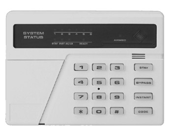
Figure 33-1: A security system keypad is used to control the security settings for a zone.
Photo courtesy of Honeywell International Inc.
Security system keypads require a 4-conductor 22-gauge copper cable. Two of the wires carry power from the control panel to the keypad, and the other two wires are used to transmit signals between the keypad and the control panel.
Door and Window Contacts
Door and window contacts are passive switches and don’t require separate power from the system control panel. To connect a door or window contact to the control panel, use 2-conductor 22-gauge unshielded copper cable. Door and window contacts can be wired in series in a loop, with the wiring from the last contact looping back to the first contact. In this configuration, a signal from any of the contacts in the loop will be transmitted back to the control panel from the first unit in the loop. Figure 33-2 illustrates how window contacts can be wired in series on a single loop of wire.
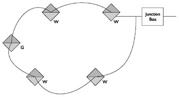
Figure 33-2: A diagram showing window and glass break sensors wired in a series loop
Door and window contacts are available in a variety of styles, including the most commonly used ones known as recessed switches that are inserted in holes drilled in the door or window and its framing (see Figure 33-3), surface-mount switches (see Figure 33-5), and roller-ball styles that operate by compressing and releasing a roller-ball (see Figure 33-4).
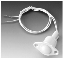
Figure 33-3: A roller-ball style door and window contact switch
Photo courtesy of Honeywell International Inc.
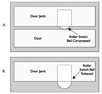
Figure 33-4: Part A of this illustration shows a recessed roller switch compressed when the door is closed. In Part B, when the door is opened, the ball is released and a signal is sent by the switch.
Figure 33-5 shows how a surface-mount window contact works. When the window is closed, a magnet in the part mounted on the window closes the switch into its normally closed (NC) position. When the window is opened, the magnet moves away from the spring-loaded switch inside the frame-mounted part and a trip signal is generated. A door contact operates in the same way; the only difference being that the magnet part moves away from the switch part when the door is opened.
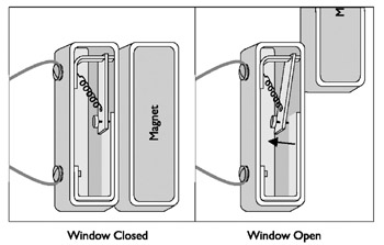
Figure 33-5: The operation of a window contact switch
To allow for a window to be open and still provide security protection, a second magnet can be mounted in the window frame to detect contact while the window is in the open position. This allows for the window to be in two positions, closed and open to this distance, and either location provides a NC (normally closed) contact.
Glass Break Sensors
The two common types of glass break sensors are acoustic (sound) and vibration (shock). Which type is better for a particular installation depends on the type of glass (plate glass, tempered glass, or laminated glass) in the window, door, or relight pane.
Acoustic Glass Break DetectorsAcoustic detectors are tuned to only pick up the sound of breaking glass and this prevents them from generating a trip signal for any other sounds. Acoustic glass break detectors are placed on a wall or ceiling near the windows to be monitored. Typically, a single acoustic sensor (see Figure 33-6) is able to monitor all the windows of a medium-sized room.
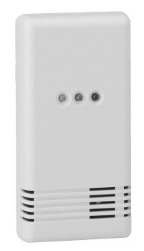
Figure 33-6: An acoustic glass break detector “hears” the sound of breaking glass and signals the alarm system.
Photo courtesy of FBII.
One challenge to installing acoustic glass break sensors is testing them. Instead of actually breaking a window to see if the sensor is working, several sensor manufacturers also sell glass break detector testers that make the sound of glass breaking—a much better way to test these units.
Acoustic sensors, also called active sensors, require power from the control panel plus two conductors for signaling; so 4-conductor 22-gauge copper wiring is required. If the sensor has a tampering relay and the homeowner wishes to connect it to the control panel, six conductors are needed.
Vibration Glass Break DetectorsVibration glass break detectors, also called passive detectors, are place directly on the glass or on the window frame very close to the window. If an intruder knocks or taps on the glass or breaks it, the vibration is sensed and a trip signal is generated.
Vibration detectors, see Figure 33-7, are passive devices that don’t require power from the control panel. Two-conductor 22-gauge wire is used to connect the detector to the control panel.
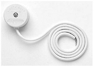
Figure 33-7: A vibration glass break detector is mounted on a windowpane to sense vibrations from knocks, taps, or hits on a window.
When deciding the type of glass break detector to install, be sure to consider if power is available to drive the acoustic sensors. When strategically placed, acoustic sensors can cover more than one window at a time but with vibration detectors there needs to be one installed on every window to be protected.
Motion Sensors
Two technologies are used in motion sensors: passive IR (PIR) or active ultrasound. Regardless of the technology used, the wiring requirements are the same. The most important issue when installing a motion sensor is placement in the room. If the purpose of the sensor is to detect someone entering the room, the sensor cannot be placed so that an opening door blocks the sensor. The sensor should be placed so that it monitors the areas of a room where the homeowners have the most concern. The recommended height of a motion sensor is 7-feet above the floor.
A common cause of false alarms for standard PIR motion detectors are small children or household pets entering a room and the detector signaling a security event. Many PIR units are available with horizontal scan “pet alleys” that prevent movement by short or small children or pets from triggering an alarm. Adaptive units such as PIR/Microwave sensors self-adjust to the room and its environment and other sensors are designed to be pet-smart with horizontal bands of the scan range set aside for pets and small children. Some units even attempt to estimate the weight of a scanned object and suppress the alarm for moving objects that are estimated to weigh less than 80 pounds.
Motion sensors, like the one shown in Figure 33-8, require a minimum of four conductors between the control panel and the sensor: two to carry 12V DC power from the control panel and two to carry the trip (motion detected) signal. Some motion detectors also have additional contacts to detect attempts to tamper with the sensor and to report self-diagnostics to a control panel. Although these additional tamper monitoring terminals are generally not connected in home systems, if the homeowner wishes to include these functions in the security system, use add two additional conductors in the cable to connect the sensor to the control panel.
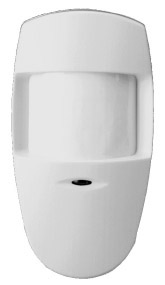
Figure 33-8: A motion sensor detects movement in a room.
Photo courtesy of Honeywell International Inc.
Smoke, Fire, and CO Detectors
Smoke, fire and carbon monoxide (CO) sensors are surface-mount devices that are installed on the ceiling or above doorways in hallways near bedrooms, kitchens (close to cooking areas), stairways, garages, mechanical rooms, and near furnaces and boilers.
Smoke, fire and CO detectors require a 4-conductor 18-gauge unshielded fire-rated cable and can be wired in series (daisy-chained) with the wire terminating at the control panel connected to the first sensor, which is then wired to the second sensor, and so on. If more than five sensors are to be installed in series, they should be split up into separate series of four units to make troubleshooting easier, should it be necessary later.
Sirens
Most residential security systems use what are called speaker sirens. The siren (sounding) unit is a module located in the security system control panel that is connected to the siren speaker using 2-conductor 18-gauge copper cable. The siren speaker is a passive device that doesn’t require power, much like a standard audio speaker but does require a heavier gauge cable than the sensors so that the sound signal is not lost as it travels over the cable.
Speaker sirens are available in two general styles, horn or surface-mount. Horn-style speaker sirens are typically used for exterior applications or placed in an out-of-the-way location, like an attic or a garage. Surface mount speakers (see Figure 33-9) are like small audio speakers that can be mounted in a room or another interior location.
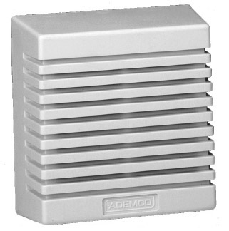
Figure 33-9: A surface-mount speaker siren.
Photo courtesy of Ademco.
Low Temperature Sensors
There are two types of low-temperature sensors: those that have a mechanical switch, also called a “freezestat,” and those that use a length of tubing that acts as an averaging sensor. In either case, when the temperature falls below a certain level, for example 39 degrees Fahrenheit or 41 degrees Fahrenheit (both common settings), the sensor sounds an audible signal, if desired, and transmits a signal to a security system controller. Some devices are hardwired and send signals through a relay and others connect using an RJ-12 connection to structured wiring.
Water Detectors
These types of sensors or detectors are also called leak detectors, and what they do is detect water leaks by monitoring for water pooling in a certain area or any detectable change in the water pressure in a pipe or tube. Nearly all water detector sensors can be connected to a home security network through either an interface module or via a relay connection on the sensor.
Humidity Sensors
Humidity sensors monitor the moisture content of the air inside a home or enclosed area. Most of the better humidity sensors have a high setting and a low setting that signals when the humidity gets too low or too high. Other humidity sensors have only a single set point and either signal when the humidity is either too low or too high, but not both. Those humidity sensors that can be interfaced to a home security control system are able to connect to any system that recognizes relay signals or dry contact switches, such as PLC and other powerline technologies.
Telephone Interface Connections
Most security control panels have a relay connection that is used to seize a telephone line to transmit an alarm signal, message, or voice recording to a home security monitoring service or telephone numbers programmed in the system.
The security system control panel should be the first device on the telephone wiring in the home. This means that the RJ-31X jack on the control panel or an add-on telephone module (see Figure 33-10) should be connected directly from the NID and before the telephone distribution module of the structured wiring system. The wiring from the NID to the security control panel and between the security control panel and the telephone system panel should be Cat 5e cable.
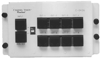
Figure 33-10: A telephone interface module with an RJ-31X jack.
Photo courtesy of ChannelVision.
Configuring the Security System Control Panel
The process and detailed steps used to configure the security system control panel for a home security system vary by manufacturer. Most systems have a proprietary configuration process that is tied to the particular modules that are included in the standard configuration of the control panel. When installing and configuring a home security system control panel, follow the manufacturer’s documentation to set up and configure the system.
Perform an interview with the homeowner about the security system to get the information necessary for system setup and user codes. Using the worksheets usually provided by the manufacturer, identify the information required. The installer can complete much of this information prior to the interview, so just get the homeowner’s approval and a few more details to help speed the process along.
When setting up an alarm system, the modules and functions that usually must be configured to ensure the proper operation of the security system are:
- Hardware and Devices
- Control panel install and power up
- Telephone connection
- Keypad hookups
- Sensor interfaces
- Fire alarm interfaces
- Sounder outputs
- Programming and Configuration (where applicable)
- Zone type setups
- User codes and setups
- Entry/exit delays
- Panic modes
- Digital communicator setup
- Alarm verification process setup
- Home control setups
- Remote telephone control
Again, be sure to follow the specifics for setup outlined in the manufacturer’s documentation.
Home Security System Testing
The installation of a home security system isn’t finished until the entire system has been completely tested and any necessary adjustments are made and retested. The testing process essentially boils down to triggering trip alerts on each installed component of the system. This means that every sensor, contact, and detector must be tested by forcing the condition it was installed to monitor: opening windows and doors and entering rooms or areas outside the home monitored by motion detectors. The complete security system should be tested, including any video surveillance (Chapter 34) or home access (Chapter 35) systems that are installed and attached to the security system control panel.
The testing should start with the testing of the components in each of the rooms in a single zone and after one zone is completely tested, proceed to the next zone. It is recommended that the first room and zone tested should be the one nearest the security system control panel. Be sure to use a zone list or wire chart to check off every device tested.
Cable Tests
During pre-wire or prior to device installation be sure to conduct cable or wire testing. You should perform the standard structured wiring cable tests, including continuity and impedance. This should be done at pre-wire so as to catch any problems that can easily be remedied while the walls are open. Testing can also be done at trim-out prior to the installation of devices to confirm all the wiring is good and if a problem exists, it would be with the devices being installed.
| CROSS-REFERENCE |
Chapters 8 and 9 detail the testing procedures for structured wiring. |
Detector Tests
After installation, hookup and setup programming of all devices, perform the following testing steps in each room:
- Set the exit timer to its lowest setting. Security systems usually have at least two settings that allow a variable amount of time before the system arms or disarms to give the homeowners time to enter the home and disarm the system or exit the home after arming the system.
- Centrally arm the system, as it would be when the homeowners were to leave the home.
- Allow the exit delay time to lapse.
- Open each protected door and window or enter a space monitored by a motion sensor to cause a trip signal and verify the alarm is triggered.
- Also test each smoke and CO sensor located in each room or zone by pressing the test button on each. If the expected alarm isn’t activated, continue to troubleshoot and test the sensor, control panel, and the alarm until all three are working properly, then move onto the next sensor.
- On most systems, you’ll need to reset the system after testing each contact, sensor, or zone.
- After completing the testing in all zones, repeat the testing with at least one sensor in each zone with the customer observing the test.
- Remember to reset the exit time setting to the desired time before leaving.
After completing the detector testing, test all of the user codes and any other unique system setup areas. Finally, orient the customer to the system and train the customer on the system’s normal operations.
Documentation on use of the security system should be given to the homeowners for reference. Documentation of the security wiring and zones should be kept in the security control panel. Documentation of system setup should also be given to the homeowner for safekeeping away from the panel and not readily accessible to others. Finally, be sure to keep documentation in the project folder of the security system setup, programming, testing, digital communicator, and ongoing maintenance and service of the system.
Security and Fire Alarm Testing Regulations
Many countries, states and provinces, counties, and cities have regulations or guidelines, in addition to the home security industry’s guidelines, on how frequently a home security system must be tested. Ensure the customer is aware of the regulations and guidelines. Table 33-1 lists the guidelines listed in the National Fire Protection Agency’s (NFPA) standard #72. In addition to the NFPA, testing guidelines for home security systems are developed and published by the Security Industry Association (SIA), Underwriters Laboratories (UL), American National Standards Institute (ANSI), Canadian Standards Association (CSA), and the National Burglar and Fire Alarms Association (NBFAA), as well as standards organizations and police and fire associations around the world.
|
System Component |
Testing Frequency |
|---|---|
|
Monitored control panel components |
Annually |
|
Unmonitored control panel components |
Semi-annually |
|
Control panel diagnostic services |
Annually |
|
Control panel/Telephone interface |
Annually |
|
Smoke and CO detectors |
Annually |
|
Door and window sensors |
Annually |
|
Sirens, sounding devices, and strobe lights |
Annually |
Included in Table 33-1 are testing frequencies of monitored and unmonitored control panel components. A monitored component is one that the control panel has circuitry to monitor and display an alert should the component begin to fail, even intermittently. Unmonitored components are those for which a failure is not alerted. For example, a security keypad near a back door of a home may be an unmonitored component of a security system. If the keypad malfunctions, the homeowner knows the device should be repaired or replaced, but the security system may not display a notice or signal the component failure. However, the security system should alert the homeowner if a monitored component such as a door contact or a motion sensor fail to respond to monitoring signals.
Also explain to the homeowners that they should review the alarm ordinance in effect in their city, county, or state or province, and that they may be required to get a permit or license for their home security system before it will be recognized as a legal system by that authority. As a billable service to your clients, you may identify this information and process the necessary paperwork for them.
Review
Installing security system components as part of a new construction project allows the cabling required for the sensors, contacts, and keypads to be placed in a room or zone to be installed along with or as part of the structured wiring system. If the system is installed in an existing home, wiring must be pulled through the existing walls, floor, or ceiling.
The system control panel terminates the wiring from all sensors or contacts. The system control panel should be placed in the same area as the structured wiring distribution panel or a protected area, not in the garage. The system control panel usually requires electrical wiring to an AC outlet for the plug-in power transformer.
Door and window contacts are passive switches and don’t require separate power from the system control panel. Door and window contacts are available in a variety of styles, including recessed switches, surface-mount switches, and roller-ball styles.
The two common types of glass break sensors are acoustic and vibration. The type that should be used for a particular installation depends on the type of glass used. Acoustic detectors are tuned to only pick up the sound of breaking glass in a medium sized room. Vibration glass break detectors are placed directly on the glass or the window frame of every window being protected.
Security system keypads are wall-mounted or recessed units that provide user interface to the security system to control a single zone or the whole-house system.
Motion sensors are either passive IR (PIR) or active ultrasound. The recommended height of a motion sensor is 7-feet above the floor.
Most residential security systems use speaker sirens that are activated by the control panel sending audio signals. Speaker sirens have two styles, horn or surface-mount.
Smoke, fire, and carbon monoxide (CO) sensors are surface-mount devices installed on ceilings or above doorways in hallways near bedrooms, kitchens (close to cooking areas), stairways, garages, and near furnaces and boilers. Smoke and fire detectors must be installed with fire-rated wiring.
Environmental monitoring sensors, which include low temperature sensors, water or moisture detectors, and humidity sensors, can be integrated into a security system to prevent conditions from harming the home or its contents.
Security control panels use a relay connection inside an RJ-31 telephone jack to seize a telephone line and transmit an alarm signal, message, or voice recording to a home security monitoring service or programmed phone numbers. The security system control panel should be the first device on the telephone system.
The process and detailed steps used to configure the security system control panel for a home security system varies by manufacturer, and a proprietary configuration process is used to configure the control panel. When installing and configuring a home security system control panel, follow the manufacturer’s documentation to set up and configure the system.
The installation of a home security system can be considered finished when the entire system has been completely tested and any necessary adjustments are made and retested. The testing process involves triggering trip alerts on each installed component of the system. Testing should begin with cable or wire testing and continue by testing the sensors and contacts in each room or zone. Documentation should be done of wiring and zones and kept inside the security panel. Documentation of setup should be given to the homeowner for safekeeping and all documentation should be kept in the installation company’s project folder.
Many countries, states and provinces, counties, and cities have regulations or guidelines concerning the frequency for home security system testing. Homeowners should be made aware of any alarm ordinances in effect in their city, county, or state or province.
Questions
- In a home security system, where do home runs to zone sensors and contacts terminate?
- Security system control panel
- Home automation controller
- Keypad
- Wiring distribution panel
- Which of the following is not a passive device?
- Door contact
- PIR motion detector
- Vibration glass break sensor
- Window contact
- Which type of glass break sensor is typically mounted directly to the glass of a window or door?
- Acoustic
- Vibration
- PIR
- All of the above
- At what height should a wall-mounted motion detector be installed?
- 4 feet
- 5 feet
- 7 feet
- Even with light switches and keypads
- On some sensors, there are tamper sensors and self-diagnostic relays. When these options are wired, what wire/cable should be used to completely wire a motion sensor?
- 4-conductor 22-gauge unshielded copper wire
- Two runs of 4-conductor 22-gauge unshielded copper wire
- Cat 5e
- None of the above; motion sensors are passive devices.
- A speaker siren is a self-contained device that generates its own audible sounds.
- True
- False
- Which of the following is not a recommended location for a smoke detector?
- Bedrooms
- Hallways near bedrooms
- Kitchen
- Bathroom
- What connector type is used to connect a security system control panel to a telephone interface?
- RJ-11
- RJ-21X
- RJ-31X
- RJ-45
- Which of the following standards organizations issues guidelines for the frequency of home security system component testing?
- ANSI
- CSA
- NFPA
- UL
- All of the above
- Which of the following security system elements should be checked and tested at least semi-annually?
- Monitored control panel components
- Unmonitored control panel components
- Smoke and CO detectors
- Door and window sensors
Answers
- A. The home run wiring of the security system could be routed through the structured wiring distribution panel or the home automation controller, but this approach would complicate the home’s wiring unnecessarily. Keypads only serve as user interfaces and zone controls in a security system.
- B. PIR motion detector is the only active (powered) device.
- B. PIR is not a type of glass break sensor and acoustic sensors are typically mounted where they can listen and monitor all of the windows in a room.
- C. This height allows the sensor to scan the full-height of any person entering or occupying a room.
- B. Six conductors are required to complete the wiring of a sensor with tamper detection.
- B. Speaker sirens receive audio signals from a siren module installed in the security system control panel.
- D. It is not necessary to install a smoke detector here. The other choices are locations in which a smoke detector should be installed.
- D. A telephone interface module with an RJ-31X jack facilitates line seizure and the ability to place a security alert on a telephone line.
- E. All of these organizations, plus several others, create testing frequency standards for fire and intruder alarms systems.
- B. The other security system components should be tested annually.
Part I - Home Technology Installation Basics
- Wire and Cable Basics
- Connector Types and Uses
- Wiring Installation Practices
- Codes, Standards, and Safety Practices
Part II - Structured Wiring
- Infrastructure Wiring Basics
- Planning a Structured Wiring Installation
- Rough-In Installation
- Trim-Out Installation
- Troubleshooting Structured Wiring
Part III - Home Computer Networks
- Computer Network Basics
- Computer Network Hardware
- Computer Network Software
- Designing and Installing a Computer Network
- Troubleshooting a Home Network
Part IV - Audio/Video Systems
- Distributed Audio System Basics
- Designing and Installing Distributed Audio Systems
- Distributed Video Basics
- Designing and Installing Distributed Video Systems
- Troubleshooting Audio Systems
- Troubleshooting Video Systems
Part V. Home Lighting Management Systems
- Home Lighting Basics
- Home Lighting Devices
- Designing a Home Lighting Control System
- Installing a Home Lighting Control System
- Troubleshooting and Maintaining Lighting Control Systems
Part VI - Telecommunications
- Home Communication System Basics
- Designing and Installing a Home Telephone System
- Troubleshooting a Home Communication System
Part VII - HVAC and Water Management
Part VIII - Security System Basics
- Security System Basics
- Designing a Home Security System
- Installing a Home Security System
- Troubleshooting and Maintaining a Home Security System
- Home Security Surveillance Systems
- Home Access Control Systems
Part IX - Home Technology Integration
- Defining Users Needs and Desires
- User Interfaces
- Home Automation Controllers
- Programming
- Integrating the Connected Home
- Other Home Technology Integration Devices
Part X - Appendices
EAN: N/A
Pages: 300
