Telecommunications and Network Security
Overview
The Telecommunications and Network Security domain is the most detailed and comprehensive domain of study for the CISSP test.
Caveat: If you’re an experienced network engineer, some of this information may seem simplistic or out of date. This is not the latest and greatest network security info, but this information is what you’ll need to know to study for the CISSP exam.
The professional should fully understand the following:
- Communications and network security as it relates to voice, data, multimedia, and facsimile transmissions in terms of local area, wide area, and remote access networks
- Communications security techniques to prevent, detect, and correct errors so that integrity, availability, and the confidentiality of transactions over networks may be maintained
- Internet/intranet/extranet in terms of firewalls, routers, gateways, and various protocols
- Communications security management and techniques that prevent, detect, and correct errors so that the confidentiality, integrity, and availability of transactions over networks may be maintained
The Telecommunications and Network Security domain includes the structures, transmission methods, transport formats, and security measures that provide confidentiality, integrity, availability, and authentication for transmissions over private and public communications networks and media. This domain is the information security domain that is concerned with protecting data, voice, and video communications and ensuring the following:
- Confidentiality. Making sure that only those who are supposed to access the data can access it. Confidentiality is the opposite of disclosure.
- Integrity. Making sure that the data has not been changed by accident or malice. Integrity is the opposite of alteration.
- Availability. Making sure that the data is accessible when and where it is needed. Availability is the opposite of destruction.
The Telecommunications Security domain of information security is also concerned with the prevention and detection of the misuse or abuse of systems, which poses a threat to the tenets of Confidentiality, Integrity, and Availability (C.I.A.).
The C I A Triad
The fundamental information systems security concept of C.I.A. relates to the Telecommunications domain in the following three ways.
Confidentiality
Confidentiality is the prevention of the intentional or unintentional unauthorized disclosure of contents. Loss of confidentiality can occur in many ways. For example, loss of confidentiality can occur through the intentional release of private company information or through a misapplication of network rights.
Some of the elements of telecommunications used to ensure confidentiality are:
- Network security protocols
- Network authentication services
- Data encryption services
Integrity
Integrity is the guarantee that the message sent is the message received and that the message is not intentionally or unintentionally altered. Loss of integrity can occur either through an intentional attack to change information (for example, a web site defacement) or, most commonly, through accidental alteration of data by an operator. Integrity also contains the concept of nonre-pudiation of a message source, which we will describe later.
Some of the elements used to ensure integrity are:
- Firewall services
- Communications Security Management
- Intrusion detection services
Availability
This concept refers to the elements that create reliability and stability in networks and systems. Availability ensures that connectivity is accessible when needed, allowing authorized users to access the network or systems. Also included in that assurance is the guarantee that security services for the security practitioner are usable when they are needed. The concept of availability also tends to include areas in Information Systems (IS) that are traditionally not thought of as pure security (such as guarantee of service, performance, and up time) yet are obviously affected by an attack such as a denial of service (DoS).
Some of the elements that are used to ensure availability are:
- Fault tolerance for data availability, such as backups and redundant disk systems
- Acceptable logins and operating process performances
- Reliable and interoperable security processes and network security mechanisms
You should also know another point about availability: The use of ill-structured security mechanisms can also affect availability. Overengineered or poorly designed security systems can impact the performance of a network or system as seriously as an intentional attack can.
The C.I.A. triad is often represented by a triangle, as shown in Figure 3-1.
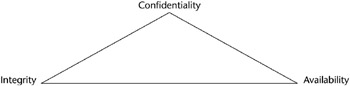
Figure 3-1: The C.I.A. triad.
Before we start to look at the various infrastructure devices and elements, we need to take a quick look at the OSI model and the TCP/IP protocol suite. These devices use many different protocols at varying OSI model layers, and the CISSP candidate will need to know one from another.
Protocols
In this section, we will examine the OSI and the TCP/IP layered models and the protocols that accompany each of these models.
A protocol is a standard set of rules that determine how computers communicate with each other across networks. When computers communicate with one another, they exchange a series of messages. A protocol describes the format that a message must take and the way in which computers must exchange messages. Protocols enable different types of computers, such as Macintoshes, PCs, Unix systems, and so on, to communicate in spite of their differences. They communicate by describing a standard format and communication method and by adhering to a layered architecture model.
The Layered Architecture Concept
Layered architecture is a conceptual blueprint of how communications should take place. It divides communication processes into logical groups called layers.
There are many reasons to use a layered architecture:
- To clarify the general functions of a communications process rather than focusing on the specifics of how to do it
- To break down complex networking processes into more manageable sublayers
- To enable interoperability by using industry-standard interfaces
- To change the features of one layer without changing all of the programming code in every layer
- To make for easier troubleshooting
How Data Moves through a Layered Architecture
Data is sent from a source computer to a destination computer. In a layered architecture model, the data passes downward through each layer from the highest layer (the Application Layer, Layer 7 in the OSI model) to the lowest layer (the Physical Layer, Layer 1 of the OSI model) of the source. It is then transmitted across the medium (cable) and is received by the destination computer, where it is passed up the layers in the opposite direction from the lowest (Layer 1) to the highest (Layer 7).
LAYERED MODELS
Layered models serve to enhance the development and management of a network architecture. They primarily address issues of data communications, but they also include some data processing activities at the upper layers. These upper layers address application software processes, the presentation format, and the establishment of user sessions. Each independent layer of a network architecture addresses different functions and responsibilities. All of these layers work together to maximize the performance of the process and interoperability. Examples of the various functions addressed are data transfer, flow control, sequencing, error detection, and notification.
Each of the various protocols operates at specific layers. Each protocol in the source computer has a job to do: Each one is responsible for attaching its own unique information to the data packet when it comes through its own layer. When the data packet reaches the destination computer, it moves up the model. Each protocol on the destination computer also has a job to do: Each protocol detaches and examines only the data that was attached by its protocol counterpart at the source computer; then it sends the rest of the packet up the protocol stack to the next higher layer. Each layer at each destination sees and deals only with the data that was packaged by its counterpart on the sending side.
Open Systems Interconnect (OSI) Model
In the early 1980s, the Open Systems Interconnect (OSI) reference model was created by the International Organization for Standardization (ISO) to help vendors create interoperable network devices. The OSI reference model describes how data and network information are communicated from one computer through a network media to another computer.
The OSI reference model breaks this approach into seven distinct layers. Layering divides a piece of data into functional groups that permit an easier understanding of each piece of data. Each layer has a unique set of properties and directly interacts with its adjacent layers. The process of data encapsulation wraps data from one layer around a data packet from an adjoining layer.
DATA ENCAPSULATION
Data encapsulation is the process in which the information from one data packet is wrapped around or attached to the data of another packet. In the OSI reference model, each layer encapsulates the layer immediately above it as the data flows down the protocol stack. The logical communication that happens at each layer of the OSI reference model does not involve a separate physical connection, because the information that each protocol needs to send is encapsulated within the protocol layer.
The Seven Layers
The OSI reference model is divided into seven layers, which we will examine here. (The mnemonic phrase “All People Seem to Need Data Processing” (APSTNDP) can be used to remember the names of the OSI layers.)
- Application Layer (Layer 7). The Application Layer of the OSI model supports the components that deal with the communication aspects of an application. The Application Layer is responsible for identifying and establishing the availability of the intended communication partner. It is also responsible for determining whether sufficient resources exist for the intended communication. This layer is the highest level and is the interface to the user. The following are some examples of Application Layer applications:
- World Wide Web (WWW)
- File Transfer Protocol (FTP)
- Trivial File Transfer Protocol (TFTP)
- Line Printer Daemon (LPD)
- Simple Mail Transfer Protocol (SMTP)
- Presentation Layer (Layer 6). The Presentation Layer presents data to the Application Layer. It functions essentially as a translator, such as Extended Binary-Coded Decimal Interchange Code (EBCDIC) or American Standard Code for Information Interchange (ASCII). Tasks such as data compression, decompression, encryption, and decryption are all associated with this layer. This layer defines how the applications can enter a network. When you are surfing the Web, most likely you are frequently encountering some of the following Presentation Layer standards:
- Hypertext Transfer Protocol (HTTP)
- Tagged Image File Format (TIFF), a standard graphics format
- Joint Photographic Experts Group ( JPEG), a standard for graphics defined by the Joint Photographic Experts Group
- Musical Instrument Digital Interface (MIDI), a format used for digitized music
- Motion Picture Experts Group (MPEG), the Motion Picture Experts Group’s standard for the compression and coding of motion video
- Session Layer (Layer 5). The Session Layer makes the initial contact with other computers and sets up the lines of communication. It formats the data for transfer between end nodes, provides session restart and recovery, and performs the general maintenance of the session from end to end. The Session Layer offers three different modes: simplex, half duplex, and full duplex. It also splits up a communication session into three different phases: connection establishment, data transfer, and connection release. Some examples of Session Layer protocols are:
- Network File System (NFS)
- Structured Query Language (SQL)
- Remote Procedure Call (RPC)
- Transport Layer (Layer 4). The Transport Layer defines how to address the physical locations and devices on the network, how to make connections between nodes, and how to handle the networking of messages. It is responsible for maintaining the end-to-end integrity and control of the session. Services located in the Transport Layer both segment and reassemble the data from upper-layer applications and unite it onto the same data stream, which provides end-to-end data transport services and establishes a logical connection between the sending host and destination host on a network. The Transport Layer is also responsible for providing mechanisms for multiplexing upper-layer applications, session establishment, and the teardown of virtual circuits. Examples of Transport Layer protocols are:
- Transmission Control Protocol (TCP)
- User Datagram Protocol (UDP)
- Sequenced Packet Exchange (SPX)
- Network Layer (Layer 3). The Network Layer defines how the small packets of data are routed and relayed between end systems on the same network or on interconnected networks. At this layer, message routing, error detection, and control of node data traffic are managed. The Network Layer’s primary function is the job of sending packets from the source network to the destination network. Therefore, the Network Layer is primarily responsible for routing. Examples of Network Layer protocols are:
- Internet Protocol (IP)
- Open Shortest Path First (OSPF)
- Internet Control Message Protocol (ICMP)
- Routing Information Protocol (RIP)
- Data Link Layer (Layer 2). The Data Link Layer defines the protocol that computers must follow in order to access the network for transmitting and receiving messages. Token Ring and Ethernet operate within this layer. This layer establishes the communications link between individual devices over a physical link or channel. It also ensures that messages are delivered to the proper device and translates the messages from layers above into bits for the Physical Layer to transmit. It also formats the message into data frames and adds a customized header that contains the hardware destination and source address. The Data Link Layer contains the Logical Link Control Sublayer and the Media Access Control (MAC) Sublayer. Bridging is a Data Link Layer function. Examples of Data Link Layer protocols are:
- Address Resolution Protocol (ARP)
- Serial Line Internet Protocol (SLIP)
- Point-to-Point Protocol (PPP)
- Physical Layer (Layer 1). The Physical Layer defines the physical connection between a computer and a network and converts the bits into voltages or light impulses for transmission. It also defines the electrical and mechanical aspects of the device’s interface to a physical transmission medium, such as twisted pair, coaxial, or fiber-optic. Communications hardware and software drivers are found at this layer as well as electrical specifications, such as EIA-232 (RS-232) and Synchronous Optical NETwork (SONET). The Physical Layer has only two responsibilities: It sends bits and receives bits. Signal regeneration and repeating is primarily a Physical Layer function. The Physical Layer defines standard interfaces such as:
- EIA/TIA-232 and EIA/TIA-449
- X.21
- High-Speed Serial Interface (HSSI)
OSI Security Services and Mechanisms
OSI defines six basic security services to secure OSI communications. A security service is a collection of security mechanisms, files, and procedures that help protect the network. They are:
- Authentication
- Access control
- Data confidentiality
- Data integrity
- Nonrepudiation
- Logging and monitoring
In addition, the OSI model defines eight security mechanisms. A security mechanism is a control that is implemented in order to provide the six basic security services. These are:
- Encipherment
- Digital signature
- Access control
- Data integrity
- Authentication
- Traffic padding
- Routing control
- Notarization
Transmission Control Protocol Internet Protocol (TCP IP)
Transmission Control Protocol/Internet Protocol (TCP/IP) is the common name for the suite of protocols originally developed by the Department of Defense (DoD) in the 1970s to support the construction of the Internet. The Internet is based on TCP/IP, which is named for the two best-known protocols in the suite. A CISSP candidate should be familiar with the major properties of TCP/IP and should know which protocols operate at which layers of the TCP/IP protocol suite.
- Application Layer. This layer isn’t really in TCP/IP; it’s made up of whatever application is trying to communicate using TCP/IP. TCP/IP views everything above the three bottom layers as the responsibility of the application, so that the Application, Presentation, and Session Layers of the OSI model are considered folded into this top layer. Therefore, the TCP/IP suite primarily operates in the Transport and Network Layers of the OSI model.
- Host-to-host layer. The host-to-host layer is comparable to the OSI Transport Layer. It defines protocols for setting up the level of transmission service. It provides for reliable end-to-end communications, ensures the error-free delivery of the data, handles packet sequencing of the data, and maintains the integrity of the data. The primary host-to-host layer protocols are:
- Transmission Control Protocol (TCP)
- User Datagram Protocol (UDP)
- Internet layer. The Internet layer corresponds to the OSI Network Layer. It designates the protocols relating to the logical transmission of packets over the network. It gives network nodes an IP address and handles the routing of packets among multiple networks. It also controls the communication flow between hosts. The primary Internet layer protocols are:
- Internet Protocol (IP)
- Address Resolution Protocol (ARP)
- Reverse Address Resolution Protocol (RARP)
- Internet Control Message Protocol (ICMP)
- Network access layer. At the bottom of the TCP/IP model, the network access layer monitors the data exchange between the host and the network. The equivalent of the Data-Link and Physical Layers of the OSI model, it oversees hardware addressing and defines protocols for the physical transmission of data.
TCP/IP Protocols
Table 3-1 lists some important protocols that populate the TCP/IP model and their related layers.
|
LAYER |
PROTOCOL |
|---|---|
|
Host-to-host |
Transmission Control Protocol (TCP) |
|
Host-to-host |
User Datagram Protocol (UDP) |
|
Internet |
Internet Protocol (IP) |
|
Internet |
Address Resolution Protocol (ARP) l |
|
Internet |
Reverse Address Resolution Protocol (RARP) |
|
Internet |
Internet Control Message Protocol (ICMP) |
 Open table as spreadsheet
Figure 3-2 shows OSI model layers mapped to their corresponding TCP/IP protocols.
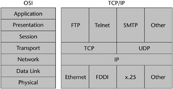
Figure 3-2: OSI model layers mapped to TCP/IP protocols.
Transmission Control Protocol (TCP)
TCP provides a full-duplex, connection-oriented, reliable connection. Incoming TCP packets are sequenced to match the original transmission sequence numbers. Because any lost or damaged packets are retransmitted, TCP is very costly in terms of network overhead and is slower than UDP. Reliable data transport is addressed by TCP to ensure that the following goals are achieved:
- An acknowledgment is sent back to the sender upon the reception of delivered segments.
- Any unacknowledged segments are retransmitted.
- Segments are sequenced back in their proper order upon arrival at their destination.
- A manageable data flow is maintained in order to avoid congestion, overloading, and data loss.
User Datagram Protocol (UDP)
UDP is similar to TCP but gives only a “best effort” delivery, which means it offers no error correction, does not sequence the packet segments, and does not care in which order the packet segments arrive at their destination. Consequently, it’s referred to as an unreliable protocol.
UDP does not create a virtual circuit and does not contact the destination before delivering the data. Thus, it is also considered a connectionless protocol. UDP imposes much less overhead, however, which makes it faster than TCP for applications that can afford to lose a packet now and then, such as streaming video or audio. Table 3-2 illustrates the differences between TCP and UDP.
|
TCP |
UDP |
|---|---|
|
Sequenced |
Unsequenced |
|
Connection-oriented |
Connectionless |
|
Reliable |
Unreliable |
|
High overhead |
Low overhead |
|
Slower |
Faster |
CONNECTION-ORIENTED VERSUS CONNECTIONLESS NETWORK SERVICES
The traditional telephone-versus-letter example may help you to understand the difference between TCP and UDP. Calling someone on the phone is like TCP because you have established a virtual circuit with the party at the other end. That party may or may not be the person you want to speak to (or might be an answering machine), but you know whether or not you spoke to them. Alternatively, using UDP is like sending a letter. You write your message, address it, and mail it. This process is like UDP’s connectionless property. You are not really sure it will get there, but you assume the post office will provide its best effort to deliver it.
TCP and UDP must use port numbers to communicate with the upper layers. Port numbers are used to keep track of the different conversations that are simultaneously crossing the network. Originating source port numbers dynamically assigned by the source host are usually some number greater than 1023.
Internet Protocol (IP)
All hosts on the Internet have a logical ID called an IP address. On the Internet, and on any network using IP, each data packet is assigned the IP address of the sender and the IP address of the recipient. Each device then receives the packet and makes routing decisions based upon the packet’s destination IP address. Each device then receives the packet and makes routing decisions based upon the packet’s destination IP address.
IP provides an unreliable datagram service, meaning that it does not guarantee that the packet will be delivered at all, that it will be delivered only once, or that it will be delivered in the order in which it was sent.
Address Resolution Protocol (ARP)
IP needs to know the hardware address of the packet’s destination so that it can send the packet. ARP is used to match an IP address to a Media Access Control (MAC) address. ARP allows the 32-bit IP address to be matched up with this hardware address.
A MAC address is a 6-byte, 12-digit hexadecimal number subdivided into two parts. The first three bytes (or first half) of the MAC address is the manu-facturer’s identifier (see Table 3-3). This can be a good troubleshooting aid if a network device is acting up, because it will isolate the brand of the failing device.[*] The second half of the MAC address is the serial number the manufacturer has assigned to the device.
|
FIRST THREE BYTES |
MANUFACTURER |
|---|---|
|
00000C |
Cisco |
|
0000A2 |
Bay Networks |
|
0080D3 |
Shiva |
|
00AA00 |
Intel |
|
02608C |
3COM |
|
080007 |
Apple |
|
080009 |
Hewlett-Packard |
|
080020 |
Sun |
|
08005A |
IBM |
ARP interrogates the network by sending out a broadcast seeking a network node that has a specific IP address and then asking it to reply with its hardware address. ARP maintains a dynamic table (known as the ARP cache) of these translations between IP addresses and MAC addresses so that it has to broadcast a request to every host only the first time it is needed. Figure 3-3 shows a flow chart of the ARP decision process.
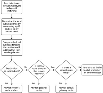
Figure 3-3: The ARP decision process.
Reverse Address Resolution Protocol (RARP)
In some cases the MAC address is known but the IP address needs to be discovered. This is sometimes the case when diskless machines are booted onto the network. Using RARP, the machine sends out a packet that includes its MAC address along with a request to be informed of which IP address should be assigned to that MAC address. A RARP server responds with the answer.
Internet Control Message Protocol (ICMP)
ICMP is a management protocol and messaging service provider for IP. ICMP’s primary function is to send messages between network devices regarding the health of the network. It can inform hosts of a better route to a destination if there is trouble with an existing route, and it can help identify the problem with a route. PING is an ICMP utility used to check the physical connectivity of machines on a network.
Other TCP/IP Protocols
- Telnet. Telnet’s function is terminal emulation. It enables a user on a remote client machine to access the resources of another machine. Telnet’s capabilities are limited to running applications; it cannot be used for downloading files.
- File Transfer Protocol (FTP). FTP is the protocol that facilitates file transfer between two machines. FTP is also employed to perform file tasks. It enables access for both directories and files and can accomplish certain types of directory operations. However, FTP cannot execute remote files as programs.
- Trivial File Transfer Protocol (TFTP). TFTP is a stripped-down version of FTP. TFTP has no directory-browsing abilities; it can do nothing but send and receive files. In contrast to FTP, authentication does not occur, so it is insecure. Some sites choose not to implement TFTP because of the inherent security risks.
- Network File System (NFS). NFS is the protocol that supports file sharing. It enables two different types of file systems to interoperate.
- Simple Mail Transfer Protocol (SMTP). SMTP is the protocol/process used to send and receive Internet e-mail. When a message is sent, it is sent to a mail queue. The SMTP server regularly checks the mail queue for messages and delivers them when they are detected.
- Line Printer Daemon (LPD). The LPD daemon, along with the Line Printer (LPR) program, enables print jobs to be spooled and sent to a network’s shared printers.
- X Window. X Window defines a protocol for the writing of graphical user interface–based client/server applications.
- Simple Network Management Protocol (SNMP). SNMP is the protocol that provides for the collection of network information by polling the devices on the network from a management station. This protocol can also notify network managers of any network events by employing agents that send alerts, called traps, to the management station. The databases of these traps are called Management Information Bases (MIBs).
- Bootstrap Protocol (BootP). When a diskless workstation is powered on, it broadcasts a BootP request to the network. A BootP server hears the request and looks up the client’s MAC address in its BootP file. If it finds an appropriate entry, it responds by telling the machine its IP address and the file from which it should boot. BootP is an Internet Layer protocol.
[*]Source: Mastering Network Security, Chris Brenton (Sybex, 1999).
LAN Technologies
A local area network (LAN) (see Figure 3-4) is a discrete network that is designed to operate in a specific, limited geographic area such as a single building or floor. LANs connect workstations and file servers together so that they can share network resources such as printers, e-mail, and files. LAN devices connect to one another by using a type of connection medium (such as copper wire or fiber optics), and they use various LAN protocols and access methods to communicate through LAN devices (such as bridges or routers). LANs can also be connected to a public switched network.
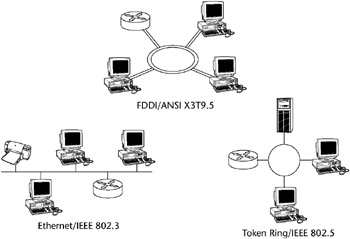
Figure 3-4: Local Area Networks (LANs).
LAN media access methods control the use of a network (its Physical and Data Link Layers). Next we will discuss the basic characteristics of Ethernet, ARCnet, Token Ring, and FDDI - the LAN technologies that account for virtually all deployed LANs.
Ethernet
The Ethernet media access method transports data to the LAN by using Carrier-Sense Multiple Access with Collision Detection (CSMA/CD), discussed shortly in the section “LAN Transmission Protocols.” Currently, this term is often used to refer to all CSMA/CD LANs. Ethernet was designed to serve on networks with sporadic, occasionally heavy traffic requirements. Ethernet defines a bus-topology LAN. Figure 3-5 shows an Ethernet network segment, and Table 3-4 lists the various Ethernet types.
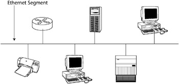
Figure 3-5: Ethernet network segment.
|
ETHERNET TYPE |
CABLE TYPE |
RATED SPEED |
RATED DISTANCE |
|---|---|---|---|
|
10Base2 |
Thinnet coax |
10 Mbps |
185 meters |
|
10Base5 |
Thicknet coax |
10 Mbps |
500 meters |
|
10BaseT |
UTP |
10 Mbps |
300 meters |
|
100BaseT (TX, T4, Fast Ethernet) |
UTP |
100 Mbps |
300 meters |
|
1000BaseT (Gigabit Ethernet) |
UTP |
100 Mbps |
300 meters |
ARCnet
ARCnet is one of the earliest LAN technologies. It uses a token-passing access method in a star topology on coaxial cable. ARCnet provides predictable, if not fast, network performance. One issue with ARCnet stations is that the node address of each station has to be manually set during installation, thus creating the possibility of duplicate, conflicting nodes.
Token Ring
IBM originally developed the Token Ring network in the 1970s. It is second only to Ethernet in general LAN popularity. The term Token Ring refers both to IBM’s Token Ring network and to IEEE 802.5 networks. All end stations are attached to a device called a Multistation Access Unit (MSAU). One station on a Token Ring network is designated the active monitor. The active monitor makes sure that there is not more than one token on the ring at any given time. If a transmitting station fails, it probably cannot remove a token as it makes it way back onto the ring. In this case, the active monitor will step in, remove the token, and generate a new one.
Fiber Distributed Data Interface (FDDI)
Like Token Ring, FDDI is a token-passing media access topology. It consists of a dual ring LAN that operates at 100 Mbps or more over fiber optic cabling. FDDI employs a token-passing media access with dual counterrotating rings, and with only one ring active at any given time. If a break or outage occurs, the ring will then wrap back the other direction, keeping the ring intact. The following are the major advantages of FDDI:
- It can operate over long distances, at high speeds, and with minimal electromagnetic or radio frequency interference present.
- It provides predictable, deterministic delays and permits several tokens to be present on the ring concurrently.
The major drawbacks of FDDI are its expense and the expertise needed to implement it properly.
A variation of FDDI called Copper Distributed Data Interface (CDDI) uses a UTP cable to connect servers or other stations into the ring instead of using fiber-optic cable. Unfortunately, this introduces the basic problems that are inherent with the use of copper cabling (length and interference problems).
DUELING ETHERNETS
Digital, Intel, and Xerox teamed up to create the original Ethernet I standard in 1980. In 1984, they followed up with the release of Ethernet II. The Institute of Electrical and Electronic Engineers (IEEE) founded the 802.3 subcommittee to create an Ethernet standard that was almost identical to the Ethernet II version. These two standards differ only in their descriptions of the Data Link Layer: Ethernet II has a “Type” field, whereas 802.3 has a “Length” field. Otherwise, both are the same in their Physical Layer specifications and MAC addressing.
Cabling Types
Network cabling commonly comes in three types: twisted pair, coaxial, and fiber-optic, as shown in Figure 3-6.
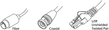
Figure 3-6: Cabling types.
Coaxial Cable (Coax)
Coax consists of a hollow outer cylindrical conductor that surrounds a single, inner wire conductor. Two types of coaxial cable are currently used in LANs: 50-ohm cable, which is used for digital signaling, and 75-ohm cable, which is used for analog signaling and high-speed digital signaling. Coax requires fixed spacing between connections.
Coax is more expensive, yet it is more resistant to electromagnetic interference (EMI) than twisted pair cabling and can transmit at a greater bandwidth and distance. However, twisted pair cabling is so ubiquitous that most installations rarely use coax except in special cases, such as broadband communications.
Coax can come in two types for LANs:
- Thinnet - (RG58 size)
- Thicknet - (RG8 or RG11 size)
There are two common types of coaxial cable transmission methods:
- Baseband - The cable carries only a single channel. Baseband is a transmission method that is accomplished by applying a direct current to a cable. The currents, or signals, hold binary information. Higher voltage usually represents the binary value of 1, whereas lower voltage represents the binary value of 0. Ethernet is baseband.
- Broadband - The cable carries several usable channels, such as data, voice, audio, and video. Broadband includes leased lines (T1 and T3), ISDN, ATM, DSL, Broadband wireless, and CATV.
Baseband uses the full cable for its transmission, whereas broadband usually divides the cable into channels so that different types of data can be transmitted at the same time. Baseband permits only one signal to be transmitted at a time, whereas broadband carries several signals over different channels.
Twisted Pair
Twisted pair cabling is a relatively low-speed transmission medium, which consists of two insulated wires that are arranged in a regular spiral pattern. The wires can be shielded (STP) or unshielded (UTP). UTP cabling is a four-pair wire medium used in a variety of networks. UTP does not require the fixed spacing between connections that is necessary with coaxial-type connections.
UTP comes in several categories. The category rating is based on how tightly the copper cable is wound within the shielding: the tighter the wind, the higher the rating and its resistance against interference and attenuation. In fact, UTP Category 3 wire was often used for phone lines, but now the Category 5 wire is the standard, and even higher categories are available. Eavesdroppers can more easily tap UTP cabling than the other cable types. The categories of UTP are:
- Category 1 UTP - Used for telephone communications and not suitable for transmitting data
- Category 2 UTP - Specified in the EIA/TIA-586 standard to be capable of handling data rates of up to 4 million bits per second (Mbps)
- Category 3 UTP - Used in 10BaseT networks and specified to be capable of handling data rates of up to 10 Mbps
- Category 4 UTP - Used in Token Ring networks and able to transmit data at speeds of up to 16 Mbps
- Category 5 UTP - Specified to be capable of handling data rates of up to 100 Mbps, is currently the UTP standard for new installations
- Category 6 UTP - Specified to be capable of handling data rates of up to 155 Mbps
- Category 7 UTP - Specified to be capable of handling data rates of up to 1 billion bits per second (Gbps)
Table 3-5 shows the UTP categories and their rated performance.
|
UTP CAT |
RATED PERFORMANCE |
COMMON APPLICATIONS |
|---|---|---|
|
Cat1 |
Under 1 MHz |
Analog Voice, older ISDN BRI |
|
Cat2 |
1 MHz |
IBM 3270, AS/400/Apple LocalTalk |
|
Cat3 |
16 MHz |
!0BaseT, 4 Mbps Token Ring |
|
Cat4 |
20 MHz |
16 Mbps Token Ring |
|
Cat5 |
100 MHz |
100BaseT |
Fiber Optic Cable
Fiber-optic cable is a physical medium that is capable of conducting modulated light transmission. Fiber-optic cable carries signals as light waves, thus allowing higher transmission speeds and greater distances due to less attenuation. This type of cabling is much more difficult to tap than other cabling and is the most resistant to interference, especially EMI. It is sometimes called optical fiber.
Fiber-optic cable is usually reserved for the connections between backbone devices in larger networks. In some very demanding environments, however, fiber-optic cable connects desktop workstations to the network or links to adjacent buildings. Fiber-optic cable is the most reliable cable type, but it is also the most expensive to install and terminate.
Fiber-optic cable has three basic physical elements:
- Core - The innermost transmission medium, which can be glass or plastic.
- Cladding - The next outer layer, also made of glass or plastic but having different properties; it helps reflect the light back into the core
- Jacket - The outermost layer, providing protection from heat, moisture, and other environmental elements
Figure 3-7 shows a cross section of a fiber optic-cable and its layers.
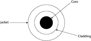
Figure 3-7: Fiber-optic cable cross section.
Cabling Vulnerabilities
Failures and issues with cables often constitute a large part of the network’s problems. The CISSP candidate should be aware of a few of them.
Coaxial cabling has two primary vulnerabilities: cable failure and length issues. All network devices attached to the same length of coax in a bus topology are vulnerable to disconnection from the network if the cable is broken or severed. This was one reason the star and ring topologies overtook the bus topology in installed base. Also, exceeding the specified effective cable length can be a source of cabling failures.
Twisted pair cables currently have two categories in common usage: CAT3 and CAT5. The fundamental difference between these two types is how tightly the copper wires are wound. This tightness determines the cable’s resistance to interference, the allowable distance it can be pulled between points, and the data’s transmission speed before attenuation and crosstalk begin to affect the signal. CAT3 is an older specification with a shorter effective distance, and it can contribute to failure if the specified effective cable length (100 meters in most cases) is exceeded.
UTP does not require the fixed spacing between connections that is necessary with some coaxial-type connections. UTP also is not as vulnerable to failure due to cable breaks as coax, but eavesdroppers can more easily tap UTP cabling than either coax or fiber.
Fiber-optic cable is immune to the effects of noise and electromagnetic interference (EMI) and therefore has a much longer effective usable length (up to 2 kilometers in some cases). It can carry a heavy load of activity much more easily than the copper types, and as such it is commonly used for infrastructure backbones, server farms, or connections that need large amounts of bandwidth. The primary drawbacks of this cable type are its cost of installation and the high level of expertise needed to have it properly terminated.
Cable failure terms to remember are:
- Attenuation - The loss of signal strength as the data travels through the cable. The higher the frequency and the longer the cable, the greater the risk of attenuation.
- Crosstalk - Because it uses less insulation than other cabling, UTP is more susceptible to crosstalk, a condition where the data signals on different wires mix.
- Noise - Environmental electromagnetic radiation from various sources can corrupt and interfere with the data signal.
Transmission Types
In addition, a CISSP candidate should know the difference between analog and digital transmission. Figure 3-8 shows the difference between an analog and a digital signal, and Table 3-6 shows the difference between analog and digital technologies.
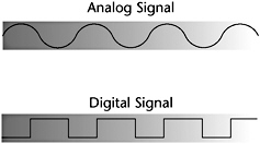
Figure 3-8: Examples of analog and digital signals.
|
ANALOG |
DIGITAL |
|---|---|
|
Infinitely varying wave form |
Square wave form |
|
Continuous signal |
Pulses |
|
Varied by amplification |
On-off only |
ASYNCHRONOUS AND SYNCHRONOUS COMMUNICATIONS
Asynchronous communication transfers data by sending bits of data sequentially. Start and stop bits mark the beginning and the end of each transfer. Communications devices must operate at the same speed to communicate asynchronously. Asynchronous communication is the basic language of modems and dial-up remote access systems. Synchronous communication is characterized by very high-speed transmission rates governed by electronic clock timing signals.
Network Topologies
A network topology defines the manner in which the network devices are organized to facilitate communications. A LAN topology defines this transmission manner for a Local Area Network. There are five common LAN topologies: bus, ring, star, tree, and mesh.
Bus
In a bus topology, all the transmissions of the network nodes travel the full length of cable and are received by all other stations (see Figure 3-9). Ethernet primarily uses this topology. This topology does have some faults. For example, when any station on the bus experiences cabling termination errors, the entire bus can cease to function.

Figure 3-9: A bus topology.
Ring
In a ring topology, the network nodes are connected by unidirectional transmission links to form a closed loop (see Figure 3-10). Token Ring and FDDI both use this topology.
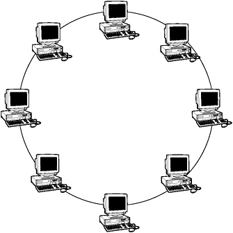
Figure 3-10: A ring topology.
Star
In a star topology, the nodes of a network are connected directly to a central LAN device (see Figure 3-11). Here is where it gets a little confusing: The logical bus and ring topologies that we previously described are often implemented physically in a star topology. Although Ethernet is logically thought of as a bus topology (its first implementations were Thinnet and Thicknet on a bus), 10BaseT is actually wired as a star topology, which provides more resiliency for the entire topology when a station experiences errors.
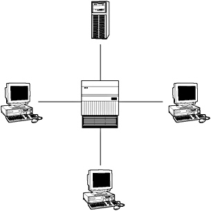
Figure 3-11: A star topology.
Tree
The tree topology (as shown in Figure 3-12) is a bus-type topology where branches with multiple nodes are possible.
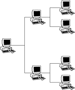
Figure 3-12: A tree topology.
Mesh
In a mesh topology, all the nodes are connected to every other node in a network (see Figure 3-13). This topology may be used to create backbone-redundant networks. A full mesh topology has every node connected to every other node. A partial mesh topology may be used to connect multiple full mesh networks together.
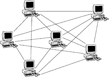
Figure 3-13: A mesh topology.
LAN Transmission Protocols
LAN transmission protocols are the rules for communication between computers on a LAN. These rules oversee the various steps in communicating, such as the formatting of the data frame, the timing and sequencing of packet delivery, and the resolution of error states.
Carrier Sense Multiple Access (CSMA)
This is the foundation of the Ethernet communications protocol. It has two functional variations: CSMA/CA and CSMA/CD; the latter is the Ethernet standard. In CSMA, a workstation continuously monitors a line while waiting to send a packet, and then transmits the packet when it thinks the line is free. If the workstation doesn’t receive an acknowledgment from the destination to which it sent the packet, it assumes a collision has occurred, and it resends the packet. This is defined as persistent carrier sense. Another version of CSMA is called nonpersistent carrier sense, in which a workstation waits a random amount of time before resending a packet, thus resulting in fewer errors.
Carrier-Sense Multiple Access with Collision Avoidance (CSMA/CA)
In this variation of CSMA, workstations are attached to two coaxial cables. Each coax cable carries data signals in one direction only. A workstation monitors its receive cable to determine whether the carrier is busy. It then communicates on its transmit cable if it detects no carrier. Thus, the workstation transmits its intention to send when it feels the line is clear due to a precedence that is based upon previously established tables. Pure CSMA does not have a feature to avoid the problem of one workstation dominating a conversation.
Carrier-Sense Multiple Access with Collision Detection (CSMA/CD)
Under the Ethernet CSMA/CD media-access process, any computer on a CSMA/CD LAN can access the network at any time. Before sending data, CSMA/CD hosts listen for traffic on the network. A host wanting to send data waits until it does not detect any traffic before it transmits. Ethernet enables any host on a network to transmit whenever the network is quiet. In addition, the transmitting host constantly monitors the wire to make sure that no other hosts begin transmitting. If the host detects another signal on the wire, it then sends out an extended jam signal, which causes all nodes on the segment to stop sending data. These nodes respond to that jam signal by waiting a bit before attempting to transmit again.
CSMA/CD was created to overcome the problem of collisions that occur when packets are simultaneously transmitted from different nodes. Collisions occur when two hosts listen for traffic and, upon hearing none, they both transmit simultaneously. In this situation, both transmissions are damaged and the hosts must retransmit at a later time.
Polling
In the polling transmission method, a primary workstation checks a secondary workstation regularly at predetermined times to determine whether it has data to transmit. Secondary workstations cannot transmit until the primary host gives them permission. Polling is commonly used in large mainframe environments where hosts are polled to determine whether they need to transmit. Because polling is very inexpensive, low-level and peer-to-peer networks also use it.
Token Passing
Used in Token Ring, FDDI, and Attached Resource Computer Network (ARC-net) networks, stations in token-passing networks cannot transmit until they receive a special frame, called a token. Possession of this token grants the right to transmit. If a node that is receiving the token has no information to send, it passes the token to the next end station. This arrangement prevents the collision problems that are present in CSMA. Token-passing networks will work well if large, bandwidth-consuming applications are commonly used on the network.
Token Ring and IEEE 802.5 are two principal examples of token-passing networks. Each station can then hold the token for a maximum period of time, as determined by the 802.5 specification.
Unlike CSMA/CD networks (such as Ethernet), token-passing networks are deterministic, which means that it is possible to calculate the maximum time that will pass before any end station can transmit. This feature and the fact that collisions cannot occur make Token Ring networks ideal for applications in which the transmission delay must be predictable and robust network operation is important. Factory automation environments are examples of such applications.
Unicast, Multicast, Broadcast
There are three flavors of LAN transmission methods:
- Unicast - The packet is sent from a single source to a single destination address.
- Multicast - The source packet is copied and sent to specific multiple destinations on the network.
- Broadcast - The packet is copied and sent to all of the nodes on a network or segment of a network.
Networking Devices
Many networking devices coexist on the Internetwork. These devices provide communications between hosts, computers, and other network devices. The following sections describe the major categories of these devices.
Hubs and Repeaters
Repeaters and hubs operate at the Physical Layer of the OSI model. Repeaters amplify the data signal to extend the length of a network segment, and they help compensate for signal deterioration due to attenuation. Hubs and repeaters are used to connect multiple LAN devices, such as servers and workstations. They do not add much intelligence to the communications process, however, because they don’t filter packets, examine addressing, or alter the data packet. Figure 3-14 shows a repeater or hub amplifying the network signal.
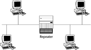
Figure 3-14: A hub or repeater.
Bridges
Like hubs, bridges also amplify the data signals, but they make intelligent decisions as to where to forward the data. A bridge forwards the data to all other network segments if the Media Access Control (MAC) address of the destination computer is not on the local network segment. If the destination computer is on the local network segment, it does not forward the data.
Because bridges operate at the Data Link Layer, OSI Layer 2, they do not use IP addresses (IP information is attached in the Network Layer, Layer 3). Because a bridge automatically forwards any broadcast traffic to all ports, an error state known as a broadcast storm can develop, overwhelming the network devices. Figure 3-15 shows a bridged network.
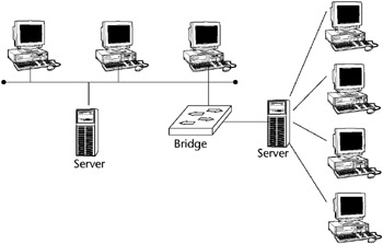
Figure 3-15: A bridged network.
BROADCASTS
A broadcast is a data packet (FF.FF.FF.FF) that is sent to all network stations at the same time. Broadcasts are an essential function built into all protocols. When servers need to send data to all the other hosts on the network segment, network broadcasts are useful. If a lot of broadcasts are occurring on a network segment, however, network performance can be seriously degraded. It is important to use these devices properly and to segment the network correctly.
Spanning Tree
To prevent broadcast storms and other unwanted side effects of looping, Digital Equipment Corporation created the Spanning Tree Protocol (STP), which has been standardized as the 802.1d specification by the IEEE.
A spanning tree uses the spanning tree algorithm (STA), which senses that the switch has more than one way to communicate with a node and determines which way is best. It blocks out the other paths but keeps track of them in case the primary path becomes unavailable.
Switches
A switch is similar to a bridge or a hub, except that a switch will send the data packet only to the specific port where the destination MAC address is located, rather than to all ports that are attached to the hub or bridge. A switch relies on the MAC addresses to determine the source and destination of a packet, which is Layer 2 networking.
Switches primarily operate at the Data Link Layer, Layer 2, although intelligent Layer 3 switching techniques (combining, switching, and routing) are being more frequently used (see “Layer 3 Switching,” in the subsequent discussion of routers). Figure 3-16 shows a switched network.
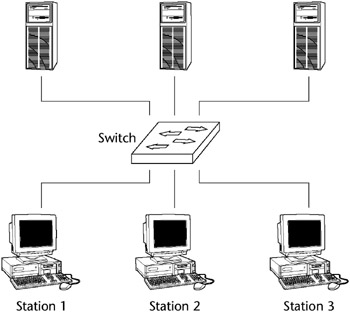
Figure 3-16: A switched network.
Transparent Bridging
Most Ethernet LAN switches use transparent bridging to create their address lookup tables. Transparent bridging allows a switch to learn everything it needs to know about the location of nodes on the network.
Transparent bridging has five steps:
- Learning
- Flooding
- Filtering
- Forwarding
- Aging
Routers
Routers add more intelligence to the process of forwarding packets. When a router receives a packet, it looks at the Network layer source and destination addresses (IP address) to determine the path the packet should take, and forwards the packet only to the network to which the packet was destined.
This prevents unnecessary network traffic from being sent over the network by blocking broadcast information and traffic to unknown addresses. Routers operate at the Network Layer, Layer 3 of the OSI protocol model. Routers are necessary when communicating between virtual LANs (VLANs). Figure 3-17 shows a routed network.
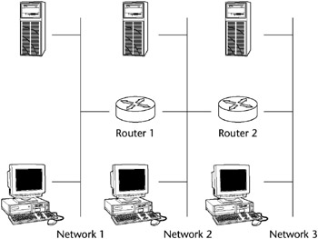
Figure 3-17: A routed network.
Routing Methodologies
Three fundamental routing methodologies exist, and other routing protocols and methods expand on these.
- Static routing
- Distance vector routing
- Link state routing
Static routing refers to the definition of a specific route in a configuration file on the router and does not require the routers to exchange route information dynamically.
Distance vector routing uses the Routing Information Protocol (RIP) to maintain a dynamic table of routing information, which is updated regularly. RIP bases its routing path on the distance (number of hops) to the destination. RIP maintains optimum routing paths by sending out routing update messages if the network topology changes (see Figure 3-18).
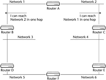
Figure 3-18: Distance vector routing.
For example, if a router finds that a particular link is faulty, it will update its routing table and then send a copy of the modified table to each of its neighbors. RIP is the oldest and most common type of dynamic routing, and it commonly broadcasts its routing table information to all other routers every minute. RIP is the earliest and the most commonly found Interior Gateway Protocol (IGP).
Link state routers function like distance vector routers, but they use only first-hand information when building routing tables by maintaining a copy of every other router’s Link State Protocol (LSP) frame. This helps to eliminate routing errors and considerably lessens convergence time.
The Open Shortest Path First (OSPF) is a link-state hierarchical routing algorithm intended as a successor to RIP. It features least-cost routing, multipath routing, and load balancing.
The Internet Gateway Routing Protocol (IGRP) is a Cisco protocol that uses a composite metric as its routing metric, including bandwidth, delay, reliability, loading, and maximum transmission unit.
Layer 3 Switching
Although most standard switches operate at the Data Link Layer, Layer 3 switches operate at the Network Layer and function like a router by incorporating some router features. The pattern matching and caching on Layer 3 switches is similar to the pattern matching and caching on a router. Both use a routing protocol and routing table to determine the best path. However, a big difference between a router and a Layer 3 switch is that Layer 3 switches have optimized hardware to pass data as fast as Layer 2 switches.
Also, a Layer 3 switch has the ability to reprogram the hardware dynamically with the current Layer 3 routing information, providing much faster packet processing. The information received from the routing protocols is used to update the hardware caching tables.
Within the LAN environment, a Layer 3 switch is usually faster than a router because it is built on switching hardware. Many of Cisco’s Layer 3 switches, such as the Cisco Catalyst 6000, are actually routers that operate faster because they are built on switching hardware with customized chips inside the box.
VLANs
A Virtual Local Area Network (VLAN) allows ports on the same or different switches to be grouped so that traffic is confined to members of that group only. It also restricts broadcast, unicast, and multicast traffic. A VLAN is a collection of nodes that are grouped together in a single broadcast domain in a switch and are based on something other than physical segment location.
A VLAN creates an isolated broadcast domain, and a switch with multiple VLANs creates multiple broadcast domains, similarly to a router. A VLAN restricts flooding to only those ports included in the VLAN. However, VLANs can’t route from one to another. Such routing would defeat the purpose of the VLAN: to isolate the traffic from the general traffic flow.
Some advantages of VLANs are:
- VLANs can aid in isolating segments with sensitive data from the rest of the broadcast domain and can increase security assurance.
- VLANs can reduce the number of router hops and increase the usable bandwidth.
- A VLAN reduces routing broadcasts, because ACLs control which stations receive what traffic.
- A VLAN is segmented logically, rather than physically.
- VLANs may be created to segregate job or department functions that require heavy bandwidth, without affecting the rest of the network.
VLANs can span across multiple switches, and you can have more than one VLAN on each switch. For multiple VLANs on multiple switches to be able to communicate via a single link between the switches, you must use a process called trunking. Trunking is the technology that allows information from multiple VLANs to be carried over just one link between switches. The VLAN Trunking Protocol (VTP) is the protocol that switches use to communicate among themselves about VLAN configuration.
When a VLAN is implemented with private-port, or single-user, switching, it provides fairly stringent security because broadcast vulnerabilities are minimized. A closed VLAN authenticates a user to an access control list on a central authentication server, where the user is assigned authorization parameters to determine his or her level of network access.
BROADCAST DOMAIN
A broadcast domain is a network (or portion of a network) that will receive a broadcast packet from any node located within that network. Normally everything on the same side of the router is all part of the same broadcast domain.
BROUTERS
Brouters are hybrid bridge/router devices. Instead of dropping an undeliverable packet, as a router would do, a brouter attempts to bridge the packet using its MAC address.
Gateways
Gateways are primarily software products that can be run on computers or other network devices. They can be multiprotocol (link different protocols) and can examine the entire packet. Mail gateways are used to link dissimilar mail programs. Gateways can also be used to translate between two dissimilar network protocols.
LAN Extenders
A LAN extender is a remote-access, multilayer switch that connects to a host router (see Figure 3-19). LAN extenders forward traffic from all the standard network-layer protocols (such as IP, IPX, and AppleTalk) and filter traffic based on the MAC address or network-layer protocol type. LAN extenders scale well, because the host router filters out unwanted broadcasts and multicasts. LAN extenders, however, are not capable of segmenting traffic or creating security firewalls.
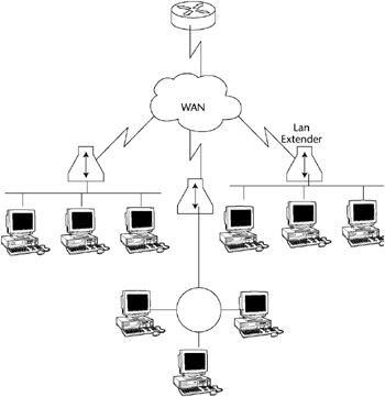
Figure 3-19: LAN extenders.
Firewall Types
Another important type of network device is a firewall. A CISSP candidate will need to know the basic types of firewalls and their functions, which firewalls operate at which protocol layer, and the basic variations of firewall architectures.
Firewalls act as perimeter access-control devices and are classified into three common types:
- Packet-level filtering firewalls
- Proxy firewalls, such as application-level or circuit-level
- Stateful inspection firewalls
Packet Filtering Firewalls
The packet-filtering firewall examines both the source and destination address of the incoming data packet. This firewall either blocks the packet or passes it to its intended destination network. The firewall can allow or deny access to specific applications or services based on the Access Control Lists (ACLs). ACLs are database files that reside on the firewall, are maintained by the firewall administrator, and tell the firewall specifically which packets can and cannot be forwarded to certain addresses.
The firewall can also be configured to allow access for only authorized application port or service numbers. It looks at the data packet to get information about the source and destination addresses of an incoming packet, the session’s communications protocol (TCP, UDP, or ICMP), and the source and destination application port for the desired service.
A packet-level firewall doesn’t keep a history of the communications session. It operates at the Network Layer of the OSI model and offers good performance. Ongoing maintenance of the ACLs can become an issue. Figure 3-20 shows an external router being used as a simple packet-filtering firewall.
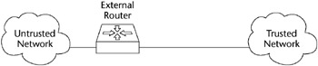
Figure 3-20: A packet-filtering router.
Application Level Firewalls
An application-level firewall (see Figure 3-21) is commonly a host computer that is running proxy server software, making it a proxy server. This firewall works by transferring a copy of each accepted data packet from one network to another, thereby masking the data’s origin. A proxy server can control which services a workstation uses on the Internet, and it aids in protecting the network from outsiders who may be trying to get information about the network’s design.
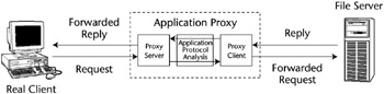
Figure 3-21: Application-level proxy firewall process.
Also called an application-layer gateway, it is commonly used with a dual-homed host. It operates at the OSI protocol Layer 7, the Application Layer. It is more secure because it examines the packet at the Application Layer, but it does so at the expense of performance.
As opposed to packet firewalls, proxy firewalls capture some session history. Proxy firewalls have higher protocols carried on low-level protocols, such as e-mail or HTML.
DYNAMIC PACKET-FILTERING FIREWALLS
A dynamic packet-filtering firewall employs a technology that enables the modification of the firewall security rule. This type of technology is used mostly for providing limited support for UDP. For a short period of time, this firewall remembers all of the UDP packets that have crossed the network’s perimeter, and it decides whether to enable packets to pass through the firewall.
Circuit Level Firewalls
Like an application-level firewall, a circuit-level firewall is used as a proxy server. It is similar to the application-level firewall in that it functions as a proxy server, but it differs in that special proxy application software is not needed.
This firewall creates a virtual circuit between the workstation client (destination) and the server (host). It also provides security for a wide variety of protocols and is easier to maintain.
Stateful Inspection Firewalls
A stateful inspection firewall intercepts incoming packets at the Network Layer and then uses an inspection engine to extract state-related information from upper layers. It maintains the information in a dynamic state table and evaluates subsequent connection attempts. Stateful inspection firewalls keep low-protocol records at the IP level.
The packets are queued and then analyzed at all OSI layers against the state table. By examining the state and context of the incoming data packets, protocols that are considered connectionless, such as UDP-based applications and Remote Procedure Calls (RPCs), can be tracked more easily.
Firewall Architectures
The four basic types of firewall architectures are:
- Packet-filtering
- Screened hosts
- Dual-homed hosts
- Screened subnet firewalls
| Note |
Keep in mind that some of these architectures are specifically associated with one of the previously discussed firewall types, while other architectures can employ a combination of types. |
Packet Filtering Routers
A packet-filtering router is the most common and oldest firewall device in use. A packet-filtering router sits between the private “trusted” network and the “untrusted” network or network segment. This firewall architecture is used as a packet-filtering firewall, described in the previous section. A packet-filtering router is sometimes used to directly manage access to a demilitarized zone (DMZ) network segment, discussed later under “Screened-Subnet Firewalls.”
Screened Host Firewalls
Like a dual-homed host, described in the next subsection, a screened-host firewall uses two network cards to connect to the trusted and untrusted networks, but it adds a screening router between the host and the untrusted network (see Figure 3-22). It provides both network-layer (routing) and application-layer (proxy) services. This type of firewall system requires an intruder to penetrate two separate systems before he or she can compromise the trusted network.
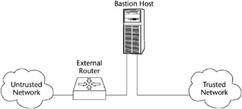
Figure 3-22: A screened-host firewall.
The host is configured between the local trusted network and untrusted network. Because the firewall can be the focus of external attacks, it is sometimes called the sacrificial lamb.
Dual Homed Host Firewalls
Another very common firewall architecture configuration is the Dual-Homed Host (see Figure 3-23). A dual-homed host has two network interface cards (NICs) but no screening router. It uses two NICs to attach to two separate networks, commonly a trusted network and an untrusted network.
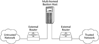
Figure 3-23: A dual-homed host firewall.
This architecture is a simple configuration that consists of a single computer (the host) with two NICs: One is connected to the local trusted network and the other is connected to the Internet or an untrusted external network. A dual-homed host firewall usually acts to block or filter some or all of the traffic trying to pass between the networks.
IP traffic forwarding is usually disabled or restricted; all traffic between the networks and the traffic’s destination must pass through some kind of security inspection mechanism.
The host’s routing capabilities must be disabled so that it does not unintentionally enable internal routing, which will connect the two networks together transparently and negate the firewall’s function. Many systems come with routing enabled by default, such as IP forwarding, which makes the firewall useless.
Screened Subnet Firewalls
One of the most secure implementations of firewall architectures is the screened-subnet firewall. A screened-subnet firewall also uses two NICs, but it has two screening routers with the host acting as a proxy server on its own network segment. One screening router controls traffic local to the network, while the second monitors and controls incoming and outgoing Internet traffic.
It employs two packet-filtering routers and a bastion host. Like a screened-host firewall, this firewall supports both packet filtering and proxy services, yet it can also define a demilitarized zone (DMZ).
A DMZ is a network added between an internal network and an external network in order to provide an additional layer of security. Sometimes it is also called a perimeter network. The DMZ creates a small network between the untrusted network and the trusted network where the bastion host and other public Web services exist. The outside router provides protection against external attacks, while the inside router manages the private network access to a DMZ by routing it through the bastion host.
Many firewalls allow you to place a network in the demilitarized zone (DMZ). Figure 3-24 shows a common firewall implementation employing a DMZ.
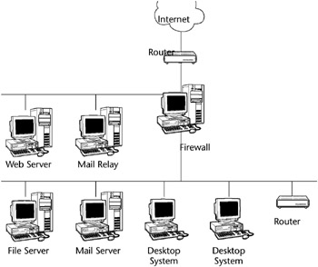
Figure 3-24: Common firewall implementation.
BASTION HOST
A bastion host is any computer that is fully exposed to attack by being on the public side of the demilitarized zone (DMZ), unprotected by a firewall or filtering router. Firewalls and routers, anything that provides perimeter access-control security, can be considered bastion hosts. Other types of bastion hosts can include Web, mail, DNS, and FTP servers. Often a bastion host is used as a sacrificial lamb. Because of their exposure, a great deal of effort must be put into designing and configuring bastion hosts to minimize the chances of penetration.
A WORD ABOUT NETWORK ARCHITECTURES
Network architecture refers to the communications products and services that ensure that the various components of a network, such as devices, protocols, and access methods, work together. Originally, a manufacturer’s network system often did not interoperate within its own product line, much less enable connectivity with the products of other manufacturers. Although IBM’s Systems Network Architecture (SNA) and Digital Equipment Corporation’s DECnet were seen as an advance in solving these problems within the vendor’s product line, they still did not interoperate outside of that product line. The Open Systems Interconnection (OSI) model by the International Organization for Standardization (ISO) was a big step in solving this problem. Other network architecture examples include the Xerox Networking System (XNS) and the Advanced Research Projects Agency Network (ARPANET), the originator of the Internet. These and other standard computer network architectures divide and subdivide the various functions of data communications into isolated layers, which makes it easier to create products and standards that can interoperate.
SOCKS
A Socket Security (SOCKS) server provides another variation of firewall protection. SOCKS is a Transport Layer, secure networking proxy protocol. SOCKS replaces the standard network systems calls with its own calls. These calls open connections to a SOCKS proxy server for client authentication transparently to the user. Common network utilities, such as Telnet or FTP, need to be SOCKS-ified, or have their network calls altered to recognize SOCKS proxy calls.
This is a circuit-level proxy server that does not require the server resource overhead of conventional proxy servers. SOCKS uses port 1080 and is used both for outbound host access by a workstation and to allow a host outside of a firewall to connect transparently and securely through the firewall.
As a consequence, some sites may have port 1080 opened for incoming connections to a system running a SOCKS daemon. One of the more common uses of SOCKS is to allow ICQ traffic to hosts that are behind a firewall.
Common Data Network Services
Some of the common services that a data network provides are:
- File services - Sharing data files and subdirectories on file servers, discussed in more detail subsequently
- Mail services - Sending and receiving e-mail internally or externally through an e-mail gateway device
- Print services - Printing documents to a shared printer or a print queue/spooler
- Client/server services - Allocating computing power resources among workstations with some shared resources centralized in a file server
- Domain Name Service (DNS) - Resolving hostnames to IP addresses, matching Internet Uniform Resource Locator (URL) requests with the actual address or location of the server that provides that URL; a distributed database system that maps host names to IP addresses
File Transfer Services
A server providing File Transfer Protocol (FTP) services can allow fully anonymous login without requiring passwords, or it can be set up to require a valid username/password pair. FTP servers provide a simple interface resembling a standard Unix file directory. Users can retrieve files and then view or execute the files later, if they have the appropriate applications.
However, if an FTP server is not configured correctly, it can provide access to any file found on the host computer or even on the network connected to the host computer. FTP servers should be restricted to accessing a limited directory space and should require the use of passwords whenever feasible.
Sometimes an organization may wish to support an anonymous FTP server to allow all external users the ability to download nonsensitive information without using strong authentication. In this case, FTP should be hosted outside the firewall or on a service network not connected to corporate networks that contain sensitive data. Table 3-7 shows a sample of such an FTP policy.
|
POLICY STATEMENT |
NONANONYMOUS FTP SERVICE |
ANONYMOUS FTP SERVICE |
|---|---|---|
|
Require FTP server outside the firewall |
N |
Y |
|
Require FTP server on the service network |
N |
Y |
|
Require FTP server on protected network |
Y |
N |
|
Require FTP server on the firewall itself |
N |
N |
|
FTP server will be accessed by Internet |
N |
Y |
FTP AND FIREWALL PROXY
Applications gateways may require a proxy for FTP services to be supported through the firewall. All incoming requests for FTP network services should go through the appropriate proxy on the firewall regardless of which host on the internal network will be the final destination. These application-level firewalls should be configured such that outbound network traffic appears as if the traffic had originated from the firewall (i.e., only the firewall is visible to outside networks). In this manner, direct access to network services on the internal network is not allowed.
SFTP
SFTP (Secure File Transfer Protocol) is replacing FTP because it includes strong encryption and authentication. SFTP is an FTP-style client that can be used to exchange files over a network and is an encryption-based replacement for the insecure FTP. SFTP provides secure file transfer functionality using SSH or SSH-2; it is the standard file transfer protocol for use with the SSH-2 protocol.
Although SFTP is designed primarily to provide file transfer services, it can provide secure file system access to a remote server. An SFTP server can be designed to provide only file transfer access, or it can provide system command access as well. SFTP can restrict users to their home directories, is not vulnerable to the flashfxp transfer utility (which allows an unknown third-party to use the network for file transfer to a remote location), and is much less vulnerable to remote exploitation than standard FTP. It can be configured to authorize users with certificates as well as passwords. MacSFTP is a Macintosh application used to transfer files over TCP/IP using SFTP.
SSH SSH 2
Secure Shell (SSH) is a set of protocols that are used primarily for remote access over a network by establishing an encrypted tunnel between an SSH client and an SSH server. This protocol can be used to authenticate the client to the server. In addition, it can also provide confidentiality and integrity services. It is composed of a Transport Layer protocol, a User Authentication protocol, and a Connection protocol. A number of SSH software programs are available on the Internet for free, such as OPENSSH.
SAVING CONFIGURATION FILES AND TRIVIAL FILE TRANSFER PROTOCOL
Sometimes, when a network device fails, the configuration programmed into it is also lost. This can especially happen to routers. The procedure that is used to prevent this from occurring consists of capturing the configuration files by logging a terminal session during a configuration session and then storing that configuration on floppies or installing a Trivial File Transfer Protocol (TFTP) server. The TFTP server is then accessed during the configuration session to save or retrieve configuration information to the network device. Because TFTP is very insecure, this server must be located in a secure area.
Secure Shell version 2 (SSH-2) contains security enhancements over the original SSH and should be used in place of SSH. SSH-2 is not strictly a VPN product, but it can be used like one. SSH opens a secure, encrypted shell (command line) session from the Internet through a firewall to the SSH server. After the connection is established, it can be used as a terminal session or for tunneling other protocols.
SSH-2 should be used instead of Telnet when connecting to remote hosts. Tunneling features available in SSH-2 can be utilized for providing secure connections to applications that are connected to a remote server, such as connecting to a POP3 e-mail server.
TFTP
Trivial File Transfer Protocol (TFTP) is a stripped-down version of FTP. TFTP has no directory browsing abilities; it can do nothing but send and receive files. TFTP is commonly used to capture router configuration files by logging a terminal session during a configuration session and then storing that configuration on a TFTP server. The TFTP server is then accessed during the configuration session to save or retrieve configuration information to the network device. However, in contrast to FTP, session authentication does not occur, so it is insecure. Some sites choose not to implement TFTP because of the inherent security risks.
Data Network Types
A CISSP candidate will also need to know the basics of the data network structures - the types of cabling, the various network access methods and topologies, and the differences between various LANs and WANs.
SONET
Synchronous Optical Network (SONET) is a standard for telecommunications transmission over fiber optics. SONET network rings transmit voice and data over fiber-optic networks. Multiple varying-speed SONET rings often communicate with each other. SONET is a self-healing technology, meaning that it can recover from a break by employing a redundant ring, making the technology fault-tolerant.
A data network consists of two or more computers that are connected for the purpose of sharing files, printers, data, and so forth. To communicate on the network, every workstation must have an NIC inserted into the computer, a transmission medium (such as copper, fiber, or wireless), a Network Operating System (NOS), and a LAN device of some sort (such as a hub, bridge, router, or switch) to physically connect the computers together.
In addition to the local area network we described, two other common types of LANs are:
- Campus Area Network (CAN) - A typically large campus network that connects multiple buildings with each other across a high-performance, switched backbone on the main campus
- Metropolitan Area Network (MAN) - Although not often used as a description, essentially a LAN that extends over a citywide (metropolitan) area, commonly a backbone network that connects business to WANs, often using SONET or FDDI rings provided by telecommunications vendors
Wide Area Networks
A Wide Area Network (WAN) is a network of subnetworks that are physically or logically interconnected over a larger geographic area than LANs.
A WAN may be privately operated for a specific user community, may support multiple communication protocols, or may provide network connectivity and services via interconnected network segments (extranets, intranets, and VPNs). WAN technologies will be examined in more detail later.
Internet
The Internet, a WAN that was originally funded by the DoD, uses TCP/IP for data interchange. The term Internet refers to the global network of public networks and Internet service providers (ISPs) throughout the world. Either public or private networks (with a VPN) can utilize the Internet.
Intranet
An intranet is an Internet-like logical network that uses a firm’s internal, physical network infrastructure. Because it uses TCP/IP and HTTP standards, it can use low-cost Internet products such as Web browsers. A common example of the use of an intranet would be a company’s human resource department publishing employee guidelines that are accessible by all company employees through the familiar Web interface. An intranet provides more security and control than a public posting on the Internet.
Extranet
Like an intranet, an extranet is a private network that uses Internet protocols. In contrast to an intranet, certain users outside the company (partners, vendors, and so forth) can access an extranet, but the general public cannot. An example of someone using this type of network is a company’s supplier accessing a company’s private network (via a VPN or Internet connection with some kind of authentication) but only having access to the information that he or she needs.
WAN Technologies
To become more familiar with the various types of WAN technologies, you must understand WAN protocols, topologies, and devices. Like LAN protocols, WAN protocols are the rules for communicating between computers on a WAN. Because the WAN is more often used for connecting diverse networks than a LAN, these protocols address the issues involved with communications between many large and disparate networks.
Dedicated Lines
A dedicated line is a communications line that is indefinitely and continuously reserved for transmission rather than being switched on and off as transmission is required. A dedicated line can be a leased line or a point-to-point link. When a communications carrier reserves a dedicated line for a customer’s private use, this is called a leased line.
Dedicated lines are also called point-to-point links, and use private circuits. Private circuits evolved before packet-switching networks. A private circuit network is a dedicated analog or digital point-to-point connection joining geographically diverse networks.
T carriers
T-carriers are dedicated lines that carry voice and data information over trunk lines. Types and speeds of various T-carriers and dedicated lines are:
- Digital Signal Level 0 (DS-0) - The framing specification used in transmitting digital signals over a single channel at 64 Kbps on a T1 facility
- Digital Signal Level 1 (DS-1) - The framing specification used in transmitting digital signals at 1.544 Mbps on a T1 facility (in the United States) or at 2.108 Mbps on an E1 facility (in Europe)
- Digital Signal Level 3 (DS-3) - The framing specification used for transmitting digital signals at 44.736 Mbps on a T3 facility
- T1 - Transmits DS-1-formatted data at 1.544 Mbps through a telephone-switching network
- T3 - Transmits DS-3-formatted data at 44.736 Mbps through a telephone-switching network
- E1 - A wide-area digital transmission scheme predominantly used in Europe that carries data at a rate of 2.048 Mbps
- E3 - The same as E1 (both can be leased for private use from common carriers), but carrying data at a rate of 34.368 Mbps
WAN Switching
When the network grows and needs more than a single point-to-point connection, WAN switching is required. There are two main flavors of WAN switching: circuit switching and packet switching.
Circuit Switched Networks
Circuit switching is defined as a switching system in which a dedicated physical circuit path must exist between the sender and receiver for the duration of the transmission or the “call.” A circuit-switched network describes a type of WAN that consists of a physical, permanent connection from one point to another. This technology is older than packet switching, which we discuss next, but it is the main choice for communications that need to be “on” constantly and have a limited scope of distribution (one transmission path only). This network type is used heavily in telephone company networks. ISDN is an example of a circuit-switched network.
Packet Switched Networks
Packet switching is defined as a networking method where nodes share bandwidth with each other by sending small data units called packets. A packet-switched network (PSN or PSDN) is a network that uses packet-switching technology for data transfer. In contrast to circuit-switched networks, the data in packet-switched networks is broken up into packets and then sent to the next destination based on the router’s understanding of the best available route. At that destination, the packets are reassembled based on their originally assigned sequence numbers. Although the data is manhandled a lot in this process, it creates a network that is very resistant to error. Table 3-8 lists some of the basic differences between circuit switching and packet switching.
|
CIRCUIT SWITCHING |
PACKET SWITCHING |
|---|---|
|
Constant traffic |
Bursty traffic |
|
Fixed delays |
Variable delays |
|
Connection-oriented |
Connectionless |
|
Sensitive to loss of connection |
Sensitive to loss of data |
|
Voice-oriented data |
Data-oriented data |
Packet-Switched Technologies
Packet-switched networks can be far more cost effective than dedicated circuits because they create virtual circuits, which are used as needed, rather than supplying a continuous dedicated circuit. Examples of packet-switching networks are X.25, Link Access Procedure-Balanced (LAPB), Frame Relay, Switched Multimegabit Data Service (SMDS), Asynchronous Transfer Mode (ATM), and Voice over IP (VoIP).[*]
- X.25. X.25 defines an interface to the first commercially successful connection-oriented packet-switching network, in which the packets travel over virtual circuits. X.25 defines the point-to-point communication between Data Terminal Equipment (DTE), Data Circuit-Terminating Equipment (DCE, commonly a modem), or a Data Service Unit/Channel Service Unit (DSU/CSU), which supports both switched virtual circuits (SVCs) and permanent virtual circuits (PVCs). X.25 defines how WAN devices are established and maintained. X.25 was designed to operate effectively regardless of the type of systems that are connected to the network. It has become an international standard and is currently much more prevalent overseas than in the United States.
- Link Access Procedure-Balanced (LAPB). Created for use with X.25, LAPB defines frame types and is capable of retransmitting, exchanging, and acknowledging frames as well as detecting out-of-sequence or missing frames.
- Frame Relay. Frame Relay is a high-performance WAN protocol that operates at the Data Link Layer of the OSI model. Originally designed for use across ISDN interfaces, it is currently used with a variety of other interfaces and is a major standard for high-speed WAN communications. Frame Relay is a successor to X.25 and LAPB. It is the fastest of the WAN protocols listed because of its simplified framing approach, which utilizes no error correction. Frame Relay uses SVCs, PVCs, and Data Link Connection Identifiers (DLCIs) for addressing. Because it requires access to a high-quality digital network infrastructure, it is not available everywhere.
- Switched Multimegabit Data Service (SMDS). SMDS is a high-speed, connectionless, packet-switched public network service that extends LAN-like performance to a metropolitan area network (MAN) or a wide area network (WAN). It’s generally delivered over a SONET ring with a maximum effective service radius of around 30 miles. It provides bandwidth to companies that need to exchange large amounts of data with other enterprises over WANs on a bursty or noncontinuous basis, by providing connectionless bandwidth upon demand.
- Asynchronous Transfer Mode (ATM). ATM is a high-bandwidth, low-delay technology that uses both switching and multiplexing. It uses 53-byte, fixed-size cells instead of frames like those used by Ethernet. It can allocate bandwidth upon demand, making it a solution for bursty applications. ATM requires a high-speed, high-bandwidth medium such as fiber optics. ATM was developed from an outgrowth of ISDN standards and is a fast-packet, connection-oriented, cell-switching technology.
- Voice over IP (VoIP). VoIP is one of several digital, multiservice access IP technologies that combine many types of data (such as voice, audio, and video) into a single IP packet, which provides major benefits in the areas of cost, interoperability, and performance.
VIRTUAL CIRCUITS
Frame Relay uses virtual circuits to forward packets. Switched virtual circuits (SVCs) are virtual circuits that are dynamically established on demand and are torn down when transmission is complete. SVCs are used in situations where data transmission is sporadic. SVCs have three phases: circuit establishment, data transfer, and circuit termination (teardown). Permanent virtual circuits (PVCs) are virtual circuits that are permanently connected. PVCs save the bandwidth that is associated with circuit establishment and teardown. A PVC provides the Frame Relay customer with guaranteed bandwidth.
Other WAN Protocols
- Synchronous Data Link Control (SDLC). SDLC is a protocol that IBM created to make it easier for its mainframes to connect to the remote offices. SDLC defines and uses a polling media access method. It consists of a primary station, which controls all communications, and one or more secondary stations. SDLC is based on dedicated, leased lines with permanent physical connections, and it has evolved into the HDLC and Link Access Procedure-Balanced (LAPB) protocols. This protocol operates at the Data Link Layer.
- High-Level Data Link Control (HDLC). Derived from SDLC, HDLC specifies the data encapsulation method on synchronous serial links by using frame characters and checksums. The ISO created the HDLC standard to support both point-to-point and multipoint configurations. Vendors often implement HDLC in different ways, which sometimes makes the HDLC protocol incompatible. It also operates at the Data Link Layer.
- High-Speed Serial Interface (HSSI). HSSI is a DTE/DCE interface that was developed to address the need for high-speed communications over WAN links. It defines the electrical and physical interfaces that DTE/DCEs use and operates at the Physical Layer of the OSI model.
Common WAN Devices
WAN devices enable the use of WAN protocols and topologies. The following are examples of these device types:
- Routers. Although previously described as a LAN device, routers are extremely important in the WAN environment - especially for IP Internet traffic.
- Multiplexers. Commonly referred to as a mux, a multiplexer is a device that enables more than one signal to be sent out simultaneously over one physical circuit.
- WAN Switches. WAN Switches are multiport networking devices that are used in carrier networks. They operate at the Data Link Layer and typically switch Frame Relay, X.25, and SMDS. These switches connect private data over public data circuits by using digital signals.
- Access Servers. An access server is a server that provides dial-in and dial-out connections to the network. These are typically asynchronous servers that enable users to dial in and connect to the LAN. Cisco’s AS5200 series of communication servers are an example of such devices.
- Modems. A modem is a device that interprets digital and analog signals, enabling data to be transmitted over voice-grade telephone lines. The digital signals are then converted to an analog form, which is suitable for transmission over an analog communications medium. These signals are then converted back to their digital form at the destination.
- Channel Service Unit (CSU)/Data Service Unit (DSU). This digital interface device terminates the physical interface on a DTE device (such as a terminal) to the interface of a DCE device (such as a switch) in a switched carrier network. These devices connect to the closest telephone company switch in a central office (CO).
Figure 3-25 shows a network that allows Internet access with several different devices.
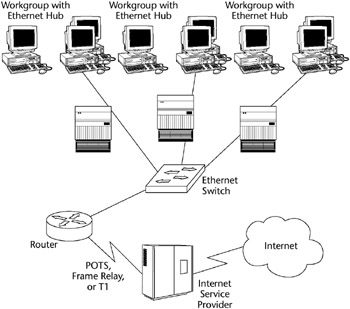
Figure 3-25: Shared Internet access with WAN and LAN devices.
Network Address Translation (NAT)
Generically, NAT (Network Address Translation) describes the process of converting an IP address valid within one network to a different IP address valid within another network. More specifically, NAT converts a private IP address on the inside, trusted network to a registered “real” IP address seen by the untrusted, outside network.
The Internet Assigned Numbers Authority (IANA) has reserved three blocks of the IP address space for private Internet addresses:
- 10.0.0.0 through 10.255.255.255
- 172.16.0.0 through 172.31.255.255
- 192.168.0.0 through 192.168.255.255
Employing these internal addresses through NAT enhances security by hiding the true IP address of the packet’s origin. As each incoming or outgoing packet is converted by NAT, the request may be authenticated.
Also, NAT helps conserve the number of global IP addresses that a company requires and allows the company to use a single IP address for its outside communications.
NAT can be statically defined, or it can be configured to dynamically use a group of IP addresses. For example, Cisco’s version of NAT lets an administrator create policies that define:
- A static one-to-one relationship between one local IP address and one global IP address
- A relationship between a local IP address to any of one of a dynamic group of global IP addresses
- A relationship between a local IP address and a specific TCP port to a static or dynamic group of global IP addresses
- A conversion from a global IP address to any one of a group of local IP addresses on a round-robin basis
NAT is described in general terms in RFC 1631, which discusses NAT’s relationship to Classless InterDomain Routing (CIDR) as a way to reduce the IP address depletion problem. NAT is often included as part of a router, and most firewall systems now include NAT capability. Figure 3-26 shows the NAT concept.
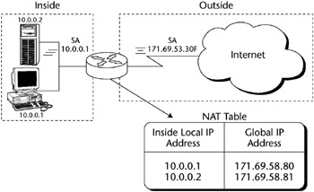
Figure 3-26: Network Address Translation (NAT).
[*]Source: Communications Systems and Networks, Ray Horak (M&T Books, 2000).
Remote Access Technologies
Remote access technologies can be defined as those data networking technologies that are uniquely focused on providing the remote user (telecommuter, Internet/intranet user, or extranet user/partner) with access into a network while striving to maintain the principal tenets of Confidentiality, Availability, and Integrity.
There are many obvious advantages to employing secure remote network access, such as the following:
- Reducing networking costs by using the Internet to replace expensive dedicated network lines
- Providing employees with flexible work styles such as telecommuting
- Building more efficient ties with customers, suppliers, and employees
Remote Access Types
While several of these remote access types share common WAN protocols, we list them here to indicate their importance in the area of remote access security.
- Asynchronous Dial-Up Access. This method is how almost everyone accesses the Internet. It is the most common remote access method for personal remote users, because it uses the existing public switched telephone network to access an ISP.
- Integrated Services Digital Network (ISDN). ISDN is a combination of digital telephony and data transport services that telecommunications carriers offer. ISDN consists of a digitization of the telephone network by permitting voice and other digital services (data, music, video, and so forth) to be transmitted over existing telephone wires. The more popular xDSL types have overtaken it in general use. ISDN has two interface types: Basic Rate Interface (BRI), which is composed of two B channels and one D channel, and Primary Rate Interface (PRI), which consists of a single 64 Kbps D channel plus 23 (T1) or 30 (E1) B channels for voice or data.
- XDSL. Digital Subscriber Line (xDSL) uses existing twisted pair telephone lines to transport high-bandwidth data to remote subscribers. It consists of a point-to-point public network that is accessed through an inhome copper phone wire. It is rapidly becoming the standard for inexpensive remote connectivity. Examples of various flavors of xDSL are:
- Asymmetric Digital Subscriber Line (ADSL) - ADSL is designed to deliver more bandwidth downstream (from the central office to the customer site) than upstream. Downstream rates range from 1.5 to 9 Mbps, whereas upstream bandwidth ranges from 16 to 640 Kbps. ADSL transmissions work at distances of up to 18,000 feet over a single copper twisted pair (although 14,400 feet is the maximum practical length).
- Single-Line Digital Subscriber Line (SDSL) - SDSL delivers 1.544 Mbps both downstream and upstream over a single copper twisted pair. This use of a single twisted pair limits the operating range of SDSL to 10,000 feet.
- High-Rate Digital Subscriber Line (HDSL) - HDSL delivers 1.544 Mbps of bandwidth each way over two copper twisted pairs. Because HDSL provides T1 speed, telephone companies have been using HDSL to provide local access to T1 services whenever possible. The operating range of HDSL is limited to 12,000 feet.
- Very-High Data Rate Digital Subscriber Line (VDSL) - VDSL delivers 13 to 52 Mbps downstream and 1.5 to 2.3 Mbps upstream over a single twisted copper pair. The operating range of VDSL is limited to 1,000 to 4,500 feet.
- Cable Modems. A cable modem provides high-speed access to the Internet by the cable company. All cable modems share a single coax line to the Internet; therefore, throughput varies according to how many users are currently using the service. It is also considered one of the most insecure of the remote access types because the local segment is typically not filtered or firewalled.
Remote Access Security Methods
The following are some common methods for securing remote access devices:
- Restricted Address. This procedure filters out unauthorized users based on their source protocol address (IP or other LAN protocol). It enables incoming calls only from specific addresses on an approved list. You should remember, however, that this procedure authenticates the node; it is not a user authentication method.
- Caller ID. Caller ID checks the incoming phone number of the caller against an approved phone list before accepting the session. This is one of the most common security methods because it is very hard to defeat. Its major drawback is that it is hard to administer for traveling users (such as users calling from a different hotel every night).
- Callback. In a callback scenario, a user attempting to initiate the session supplies a password or some type of identifying code. The access server then hangs up and calls the user back at a predetermined phone number. Again, this procedure authenticates the node, not the user, and is difficult to administer in traveling situations.
Virtual Private Networking (VPN)
A virtual private network (VPN) is created by building a secure communications link between two nodes, emulating the properties of a point-to-point private link. A VPN can be used to facilitate secure remote access into a network, securely connect two networks together, or create a secure data tunnel within a network.
The portion of the link in which the private data is encapsulated is known as the tunnel. It may be referred to as a secure, encrypted tunnel, although it’s more accurately defined as an encapsulated tunnel, because encryption may or may not be used. To emulate a point-to-point link, data is encapsulated, or wrapped, with a header that provides routing information. Most often the data is encrypted for confidentiality. This encrypted part of the link is considered the actual virtual private network connection. Figure 3-27 shows a common VPN configuration for remote access into a company intranet through the Internet.
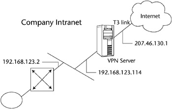
Figure 3-27: A common VPN configuration.
VPN Examples
The following are some common VPN configurations:
- Remote access VPNs
- Network-to-network VPNs
- Intranet access VPNs
Remote Access VPNs
A VPN can be configured to provide remote access to corporate resources over the public Internet to maintain confidentiality and integrity. This configuration allows the remote user to utilize whatever local ISP is available to access the Internet without forcing the user to make a long-distance or 800 call to a third-party access provider. Using the connection to the local ISP, the VPN software creates a virtual private network between the dial-up user and the corporate VPN server across the Internet. Figure 3-28 shows a remote user VPN connection.
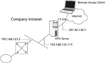
Figure 3-28: A remote access VPN.
Network-to-Network VPNs
A VPN is commonly used to connect two networks, perhaps the main corporate LAN and a remote branch office LAN, through the Internet. This connection can use either dedicated lines to the Internet or dial-up connections to the Internet. However, the corporate hub router that acts as a VPN server must be connected to a local ISP with a dedicated line if the VPN server needs to be available 24/7. The VPN software uses the connection to the local ISP to create a VPN tunnel between the branch office router and the corporate hub router across the Internet. Figure 3-29 shows a remote branch office connected to the corporate main office using a VPN tunnel through the Internet.
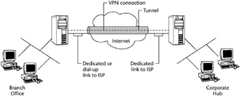
Figure 3-29: A network-to-network VPN.
Intranet Access VPNs
If remote users need to access sensitive data on a LAN physically disconnected from the rest of the corporate network, a VPN may provide the solution. A VPN allows the LAN with the sensitive data to be physically connected to the corporate internetwork but separated by a VPN server, as shown in Figure 3-30. This ensures that only authorized users on the corporate network can establish a VPN with the VPN server and gain access to the sensitive data.
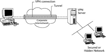
Figure 3-30: An intranet access VPN.
In this case, the VPN server is not acting as a router between the corporate internetwork and the department LAN, because a router would connect the two networks, thus allowing everyone access to the sensitive LAN.
VPN Tunneling
Tunneling is a method of transferring data from one network to another network by encapsulating the packets in an additional header. The additional header provides routing information so that the encapsulated payload can traverse the intermediate networks, as shown in Figure 3-31.
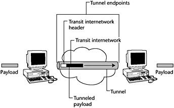
Figure 3-31: VPN tunnel and payload.
For a tunnel to be established, both the tunnel client and the tunnel server must be using the same tunneling protocol. Tunneling technology can be based on either a Layer 2 or a Layer 3 tunneling protocol. These layers correspond to the Open Systems Interconnection (OSI) Reference Model.
Tunneling, and the use of a VPN, is not intended as a substitute for encryption/decryption. In cases where a high level of security is necessary, the strongest possible encryption should be used within the VPN itself, and tunneling should serve only as a convenience.
VPN and Remote Access Protocols
Both the Point-to-Point Tunneling Protocol (PPTP) and the Layer Two Tunneling Protocol (L2TP) are Layer 2 tunneling protocols using Data Link Layer formatting and encapsulating the payload in a Point-to-Point Protocol (PPP) frame (discussed subsequently). Layer 3 protocols correspond to the Network Layer and use packets. IPSec tunnel mode is an example of a Layer 3 tunneling protocol that encapsulates IP packets in an additional IP header.
Layer 3 tunneling technologies generally assume that all of the configuration issues are preconfigured, often by manual processes. For these protocols, there may be no tunnel maintenance phase. For Layer 2 protocols, however, a tunnel must be created, maintained, and then terminated.
Point-to-Point Tunneling Protocol (PPTP)
Point-to-Point Tunneling Protocol (PPTP) works at the Data Link Layer of the OSI model. It is designed for individual client-to-server connections, so it allows only a single point-to-point connection per session. PPTP is commonly used by Windows clients for asynchronous communications. PPTP uses the native PPP authentication and encryption services.
PPTP allows IP, IPX, or NetBEUI traffic to be encrypted and then encapsulated in an IP header to be sent across a corporate IP internetwork or a public IP internetwork, such as the Internet. PPTP uses a TCP connection for tunnel maintenance and a modified version of Generic Routing Encapsulation (GRE) to encapsulate PPP frames for tunneled data. The payloads of the encapsulated PPP frames can be encrypted and compressed.
Layer 2 Tunneling Protocol (L2TP)
Layer 2 Tunneling Protocol (L2TP) is a combination of PPTP and the earlier Layer 2 Forwarding Protocol (L2F) and also works at the Data Link Layer. L2TP is an accepted tunneling standard for VPNs. Dial-up VPNs also use this standard frequently. Like PPTP, it was designed for single point-to-point client-to-server connections. Like PPTP, L2TP allows IP, IPX, or NetBEUI traffic to be encrypted and then sent over any medium that supports point-to-point datagram delivery, such as:
- IP
- X.25
- Frame Relay
- ATM
L2TP supports TACACS+ and RADIUS, but PPTP does not. L2TP running over IP networks uses UDP and a series of L2TP messages for tunnel maintenance. L2TP also uses UDP to send L2TP-encapsulated PPP frames as the tunneled data. The payloads of encapsulated PPP frames can be encrypted and compressed.
Internet Protocol Security (IPSec)
IPSec operates at the Network Layer and allows multiple simultaneous tunnels. IPSec contains the functionality to encrypt and authenticate IP data. While PPTP and L2TP are aimed more at dial-up VPNs, IPSec also encompasses network-to-network connectivity.
Although IPSec operates at the Network Layer and enables multiple simultaneous tunnels, it is not multiprotocol. IPSec has the functionality to encrypt and authenticate IP data. It is built into the new IPv6 standard and is used as an add-on to the current IPv4. IPSec tunnel mode allows IP packets to be encrypted and then encapsulated in an IP header to be sent across a corporate IP internetwork or a public IP internetwork, such as the Internet.
IPSec uses an authentication header (AH) to provide source authentication and integrity without encryption, and it uses the Encapsulating Security Payload (ESP) to provide authentication and integrity along with encryption. With IPSec, only the sender and recipient know the key. If the authentication data is valid, the recipient knows that the communication came from the sender and that it was not changed in transit.
Serial Line Internet Protocol (SLIP)
Serial Line Internet Protocol (SLIP) is a TCP/IP protocol and early de facto standard for asynchronous dial-up communication. An ISP may provide a SLIP connection for Internet access. PPP is now preferred over SLIP because it can handle synchronous as well as asynchronous communication. PPP can share a line with other users, and it has error detection that SLIP lacks.
Point-to-Point Protocol (PPP)
The Point-to-Point Protocol (PPP) defines an encapsulation method to transmit multiprotocol packets over Layer 2 point-to-point links, such as a serial interface. PPP is a full-duplex protocol that can be used on various physical media, including twisted pair or fiber-optic lines or satellite transmissions. It uses a variation of High Speed Data Link Control (HDLC) for packet encapsulation.
A user may connect to a network access server (NAS) through ISDN, ADSL, dial-up plain old telephone service (POTS), or another service and then run PPP over that connection. Most implementations of PPP provide limited authentication methods, including:
- Password Authentication Protocol (PAP)
- Challenge Handshake Authentication Protocol (CHAP)
- Microsoft Challenge Handshake Authentication Protocol (MS-CHAP)
Password Authentication Protocol
The Password Authentication Protocol (PAP) is a basic clear-text authentication scheme. The NAS requests the username and password, and PAP returns them in clear text, unencrypted. PAP user authentication is often used on the Internet, which simply sends a username and password to a server, where they are compared with a database of authorized users. While the user database may be kept in encrypted form, each ID and password is sent unencrypted.
This authentication scheme is not secure, because a third party could capture the user’s name and password and use it to get subsequent access to the NAS and all of the resources provided by the NAS. PAP provides no protection against replay attacks or remote client impersonation once the user’s password is compromised. A better variation on this method is the Challenge Handshake Authentication Protocol (CHAP).
Challenge Handshake Authentication Protocol
The Challenge Handshake Authentication Protocol (CHAP) is an encrypted authentication mechanism that avoids transmission of the actual password on the connection. The NAS sends a challenge, which consists of a session ID and an arbitrary challenge string, to the remote client. The remote client must use the MD5 one-way hashing algorithm to return the username and an encryption of the challenge, the session ID, and the client’s password. The username is sent unhashed.
CHAP is an improvement over PAP, because the clear-text password is not sent over the link. Instead, the password is used to create an encrypted hash from the original challenge. The server knows the client’s clear-text password and can, therefore, replicate the operation and compare the result to the password sent in the client’s response. CHAP protects against replay attacks by using an arbitrary challenge string for each authentication attempt. CHAP protects against remote client impersonation by unpredictably sending repeated challenges to the remote client throughout the duration of the connection.
During the CHAP process, a three-way handshake occurs:
- A link is established, and then the server agent sends a message to the machine originating the link.
- This machine then computes a hash function from the challenge and sends it to the server.
- The server determines whether this is the expected response and, if so, authenticates the connection.
At any time, the server can request the connected party to send a new challenge message. Because CHAP identifiers are changed frequently and because authentication can be requested by the server at any time, CHAP provides more security than PAP. Both CHAP and PAP are defined in RFC1334.
MS-CHAP
The Microsoft Challenge Handshake Authentication Protocol (MS-CHAP) is an encrypted authentication mechanism very similar to CHAP. As in CHAP, the NAS sends a challenge, which consists of a session ID and an arbitrary challenge string, to the remote client. The remote client must return the username and an encrypted form of the challenge string, the session ID, and the MD4-hashed password. This design, which uses a hash of the MD4 hash of the password, provides an additional level of security because it allows the server to store hashed passwords instead of clear-text passwords.
MS-CHAP also provides additional error codes, including a password-expired code, and additional encrypted client-server messages that permit users to change their passwords. In MS-CHAP, both the access client and the NAS independently generate an initial key for subsequent data encryption by MPPE. Therefore, MS-CHAP authentication is required to enable MPPE-based data encryption.
MS-CHAP version 2
MS-CHAP version 2 (MS-CHAP v2) is an updated encrypted authentication mechanism that provides stronger security. The NAS sends a challenge to the access client that consists of a session identifier and an arbitrary challenge string. The remote access client sends a response that contains the following:
- The username
- An arbitrary peer challenge string
- An encrypted form of the received challenge string
- The peer challenge string
- The session identifier
- The user’s password
The NAS checks the response from the client and sends back a response containing an indication of the success or failure of the connection attempt and an authenticated response based on the sent challenge string, the peer challenge string, the encrypted response of the client, and the user’s password. The remote access client verifies the authentication response and, if correct, uses the connection. If the authentication response is not correct, the remote access client terminates the connection.
Using this process, MS-CHAP v2 provides mutual authentication; the NAS verifies that the access client has knowledge of the user’s password, and the access client verifies that the NAS has knowledge of the user’s password. MS-CHAP v2 also determines two encryption keys: one for data sent and one for data received.
Extensible Authentication Protocol
Because most implementations of PPP provide very limited authentication methods, the Extensible Authentication Protocol (EAP) was designed to allow the dynamic addition of authentication plug-in modules at both the client and server ends of a connection.
EAP is an extension to PPP that allows for arbitrary authentication mechanisms for the validation of a PPP connection. This allows vendors to supply a new authentication scheme at any time, providing the highest flexibility in authentication uniqueness and variation. EAP is supported in Microsoft Windows 2000 and is defined in RFC 2284.
EAP Transport Level Security
EAP Transport Level Security (EAP-TLS) is an IETF standard (RFC 2716) for a strong authentication method based on public-key certificates. With EAP-TLS, a client presents a user certificate to the dial-in server, and the server presents a server certificate to the client. The client provides strong user authentication to the server, and the server provides assurance that the user has reached the server that he or she expected. Both systems rely on a chain of trusted authorities to verify the validity of the offered certificate.
EAP-TLS is the specific EAP method implemented in Microsoft Windows 2000. Like MS-CHAP and MS-CHAP v2, EAP-TLS returns an encryption key to enable subsequent data encryption by MPPE.
Wireless VPNs
Wireless LANs (WLANs) can especially benefit from a VPN. A VPN can be used to act as a gateway between the WLAN and the network and can supplement the WEP’s authentication and encryption functions. All traffic between the wired and wireless network should travel through the VPN tunnel and be encrypted with the IPSec protocol. IPSec thwarts sniffer attacks launched using applications such as AirSnort.
When a VPN client needs to access the network, it will connect to a VPN server, and the server will authenticate the client. Once authenticated, the VPN server will provide the client with an IP address and an encryption key. All communications will be carried out through this IP address. Every packet that passes through this secure tunnel between the client and server will be encrypted.
Consequently, an attacker cannot simply hijack an IP address to gain access, because he or she will not possess the encryption key. The VPN server will simply reject all connections from the attacker.
Guidelines for wireless VPN implementation include the following:
- Use VPN clients on wireless devices to enforce strong encryption and require positive authentication via hardware tokens.
- For wireless applications within the company, use a wireless VPN solution that supports a FIPS-approved data encryption algorithm to ensure data confidentiality in a WLAN environment.
- Ensure that each endpoint of the VPN remains under company control. When possible, install WLAN network APs and wVPN gateways behind network perimeter security mechanisms (e.g., firewall, IDS), so that wireless access to the internal wired network can be controlled and monitored.
More detail about wireless technologies can be found later in the chapter.
RADIUS and TACACS
As the demand for large remote access networks increases, remote access authentication systems have emerged to provide better network access security for remote clients. The two most common remote access authentication systems are Remote Authentication Dial-In User Server (RADIUS) and Terminal Access Controller Access Control System + (TACACS+), which is TACACS with additional features, including the use of two-factor authentication.
TACACS and RADIUS are standards-based, which means that they are interoperable with other systems of the same type. Some of these systems provide a centralized database that maintains user lists, passwords, and user profiles that remote access equipment on a network can access to authenticate clients.
Remote Authentication Dial-in User Service (RADIUS)
The Remote Authentication Dial-in User Service (RADIUS) protocol is a lightweight, UDP-based protocol used for managing remote user authentication and authorization. It is a fully open protocol, is distributed in source code format, and can be modified to work with any security system that is currently available on the market.
RADIUS is a distributed client/server system wherein the clients send their authentication requests to a central RADIUS server that contains all of the user authentication and network service access information (network ACLs). RADIUS servers can be located anywhere on the network, and they provide authentication and authorization for network access servers and VPNs.
RADIUS can be used with TACACS+ and Kerberos to provide CHAP remote node authentication. It provides similar user authentication (including the use of dynamic passwords) and password management as a TACACS+enabled system.
Because RADIUS does not support all protocols, it is often used as a steppingstone to a more robust TACACS+ system. Also, RADIUS does not provide two-way authentication and therefore is not commonly used for router-to-router authentication. Figure 3-32 shows a RADIUS server performing authentication within a company intranet for VPN and remote access server (RAS) clients.
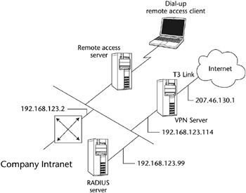
Figure 3-32: A RADIUS VPN.
Wireless RADIUS
Several 802.11 access points offer RADIUS authentication, which gives wireless clients access to network resources after supplying a username and password to a RADIUS server. Such user-based authentication provides a centrally managed method of verifying users who attempt to access the wireless network. Most RADIUS servers can handle this VPN client authentication functionality.
Some RADIUS implementations also allow the user to be authenticated via a digital key system, and they restrict access to preauthorized areas by the user. For example, Cisco’s RADIUS server makes it possible to establish access by time and date.
Terminal Access Controller Access Control System (TACACS)
TACACS is an authentication protocol that provides remote access authentication and related services, such as event logging. In a TACACS system, user passwords are administered in a central database rather than in individual routers, which provides an easily scalable network security solution. A TACACS-enabled network device prompts the remote user for a username and static password, and then the TACACS-enabled device queries a TACACS server to verify that password. TACACS does not support prompting for a password change or for the use of dynamic password tokens.
TACACS+ has superseded TACACS. TACACS+ provides the following additional features:
- The use of two-factor password authentication
- The ability for a user to change his or her password
- The capability for resynchronizing security tokens
- Better audit trails and session accounting
Network Availability
This section defines those elements that can provide for or threaten network availability. Network availability can be defined as an area of the Telecommunications and Network Security domain that directly affects the Information Systems Security tenet of availability.
High Availability and Fault Tolerance
The concept of high availability refers to a level of fault tolerance and redundancy in transaction processing and communications. Although these processes are not used solely for disaster recovery, they are often elements of a larger disaster recovery plan. If one or more of these processes are employed, the ability of a company to get back on-line is greatly enhanced.
Some concepts employed for high availability and fault tolerance are:
- Electronic vaulting. Electronic vaulting refers to the transfer of backup data to an off-site location. This is primarily a batch process of dumping the data through communications lines to a server at an alternate location.
- Remote journaling. Remote journaling consists of the parallel processing of transactions to an alternate site, as opposed to a batch dump process such as electronic vaulting. A communications line is used to transmit live data as transactions occur. This feature enables the alternate site to be fully operational at all times and introduces a very high level of fault tolerance.
- Database shadowing. Database shadowing uses the live processing advantages of remote journaling, but it creates even more redundancy by duplicating the database sets to multiple servers.
- Redundant Servers. A redundant server implementation takes the concept of RAID 1 (mirroring) and applies it to a pair of servers. A primary server mirrors its data to a secondary server, thus enabling the primary to “roll over” to the secondary in the case of primary server failure (the secondary server steps in and takes over for the primary server). This rollover can be hot or warm (that is, the rollover may or may not be transparent to the user), depending upon the vendor’s implementation of this redundancy. This process is also known as server fault tolerance. Figure 3-33 demonstrates redundant servers.
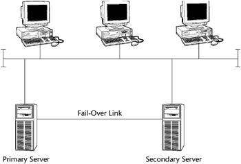
Figure 3-33: Redundant servers. - Server Clustering. A server cluster is a group of independent servers that are managed as a single system, providing higher availability, easier manageability, and greater scalability. The concept of server clustering is similar to the redundant server implementation previously discussed, except that all the servers in the cluster are online and take part in processing service requests. By enabling the secondary servers to provide processing time, the cluster acts as an intelligent entity and balances the traffic load to improve performance. The cluster looks like a single server from the user’s point of view. If any server in the cluster crashes, processing continues transparently; however, the cluster suffers some performance degradation. This implementation is sometimes called a server farm. Figure 3-34 shows a type of server clustering.
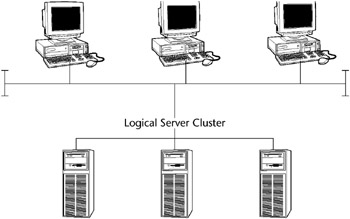
Figure 3-34: Server clustering. - Redundant communications lines. T1 and other communications lines need redundancy, because the severing of a T1 line or another type of loss of the line can cause a failure of availability. ISDN BRI is commonly used as a backup for a T1. An organization may use multiple telecommunications vendors for fault tolerance.
Wireless Technologies
Wireless technology is probably the fastest-growing area of network connectivity. Experts estimate that the number of Internet-connected PDAs, such as the Palm Pilot, will eclipse the number of personal computers in use in a few years. Security is an extreme concern here because all wireless technologies (mobile phones, satellite transmissions, and so forth) are inherently susceptible to interception and eavesdropping. Encryption standards are rapidly being developed to combat this problem.
IEEE Wireless Standards
IEEE 802.11 refers to a family of specifications for WLANs developed by a working group of the IEEE. 802.11 also generically refers to the IEEE Committee responsible for setting the various wireless LAN standards. This standards effort began in 1989 with the focus on deployment in large enterprise networking environments, effectively a wireless equivalent to Ethernet. The IEEE accepted the specification in 1997.
The 802.11 specification identifies an over-the-air interface between a mobile device wireless client and a base station or between two mobile device wireless clients. To date, there are four completed specifications in the family: 802.11, 802.11a, 802.11b, and 802.11g, with a fifth, 802.11e, in development as a draft standard. All four existing standards use the Ethernet protocol and carrier sense multiple access with collision avoidance (CSMA/CA) for path sharing.
There are several specifications in the 802.11 family, including:
- 802.11 - The original IEEE wireless LAN standard that provides 1 or 2 Mbps transmission speed in the 2.4 GHz band, using either FHSS or DSSS (see the subsection “Spread Spectrum Technologies”). The modulation used in 802.11 is commonly phase-shift keying (PSK).
- 802.11a - An extension to the original IEEE 802.11 wireless LAN standard that provides up to 54 Mbps in the 5 GHz band. 802.11a uses an orthogonal frequency division multiplexing encoding scheme rather than FHSS or DSSS.
- 802.11b - An extension to the 802.11 wireless LAN standard, it provides 11 Mbps transmission speed (but that automatically slows down to 5.5 Mbps, 2 Mbps, or 1 Mbps speeds in the 2.4 GHz band based upon the strength of the signal). 802.11b uses only DSSS. 802.11b, 1999 ratification to the original 802.11 standard, provides wireless functionality comparable to Ethernet; it is also referred to as 802.11 High Rate or Wi-Fi.
- 802.11e - The latest IEEE draft extension to provide QoS features and multimedia support for home and business wireless environments.
- 802.11f - This standard that describes how data can be shared and authenticated between APs, thus supporting seamless wireless roaming.
- 802.11g - An IEEE wireless standard that applies to wireless LANs. 802.11g provides 20 Mbps to 54 Mbps in the 2.4 GHz band.
- 802.11h - 802.11h enhances the 802.11a 5 GHz standard to allow these products to be implemented in Europe.
- 802.11i - The 802.11i standard attempts to address the array of serious security flaws inherent in 802.11 products and in WEP itself. It consists of two different approaches:
- The TKIP protocol, which generates more complex dynamic keys. TKIP is backward compatible with many WLAN systems.
- The CCM protocol (CCMP), which uses the AES algorithm with CBC-MAC (CCM). CCMP is not backward compatible.
- 802.11n - 802.11n is a very new standard operating in the 5 GHz range. It combines multiple antennas, faster encoding, and an optional doubling of spectrum to achieve raw data rates from 100 Mbps up to 600 Mbps. The standard employs multiple input, multiple output (MIMO) technology to achieve this speed. Vendors should be shipping the first n products by late 2006.
- 802.15 - IEEE 802.15 defines Wireless Personal Area Networks (WPAN), such as Bluetooth, in the 2.4–2.5 GHz band.
- 802.16 - Another wireless 802 standard, called IEEE 802 Broadband Wireless Access (802.WBA or 802.16), is under development. IEEE 802.16 standardizes the air interface and related functions associated with the wireless local loop (WLL) for wireless broadband subscriber access. Three working groups have been chartered to produce 802.16 standards: IEEE 802.16.1, air interface for 10 to 66 GHz; IEEE 802.16.2, coexistence of broadband wireless access systems; and IEEE 802.16.3, air interface for licensed frequencies (2 to 11 GHz).
802.1x
The IEEE drafted the 802.1x Port-Based Network Access Control standard in 2001 to provide enhanced security for users of 802.11b wireless LANs. It provides port-level authentication for any wired or wireless Ethernet client system. This supplement to ISO/IEC 15802-3:1998 (IEEE Std 802.1D-1998) defines the changes necessary to the operation of a MAC Bridge in order to provide port-based network access control capability.
Originally designed as a standard for wired Ethernet, 802.1x is applicable to WLANs. It leverages many of the security features used with dial-up networking; for example, it uses encryption keys that are unique for each user and each network session, and it supports 128-bit key lengths. It has a key management protocol built into its specification, which provides keys automatically. Keys can also be changed rapidly at set intervals. It will also support the use of Remote Authentication Dial-in User Service (RADIUS) and Kerberos. The 802.1x standard can be used to provide link-layer authentication, making employee authentication by active directories and databases easier.
The standard defines a client/server-based access control and authentication protocol that restricts unauthorized devices from connecting to a LAN through publicly accessible ports. The authentication server verifies each client connected to a switch port before making available any services offered by the switch or the LAN. Until the client has been authenticated, 802.1x access controls allows only Extensible Authentication Protocol over LAN (EAPOL) traffic through the port to which the client is connected. Once the client has been authenticated, normal traffic can pass through the port.
Cisco Systems has implemented 802.1x in its Aironet series of cards, and Microsoft has added the feature to Windows XP. The goal of 802.1x is to provide a level of authentication comparable to that of the wired network. Using 802.1x, any appropriated wireless NICs no longer pose a threat because the network now authenticates the user, not the hardware.
When the user (called the supplicant) wants to use the network service, he or she will connect to the access point (called the authenticator), and a RADIUS server (the authentication server) at the other end will receive the request and issue a challenge. If the supplicant can provide a correct response, it is allowed access.
Cisco introduced the Lightweight Extensible Authentication Protocol (LEAP) for its Aironet devices. Using LEAP, client devices dynamically generate a new WEP key as part of the login process instead of using a static key. In the Cisco model, the supplicant and authentication server change roles and attempt mutual communication. Using this method of authentication, the risk of authenticating to a rogue access point is minimized. After authentication, the authentication server and the supplicant determine a WEP key for the session. This gives each client a unique WEP for every session.
Spread-Spectrum Technologies
The de facto communication standard for wireless LANs is spread spectrum, a wideband radio frequency technique originally developed by the military for use in secure, mission-critical communications systems.[*] Spread spectrum uses a radio transmission mode that broadcasts signals over a range of frequencies. The receiving mobile device must know the correct frequency of the spread-spectrum signal being broadcast.
Two different spread spectrum technologies for 2.4 GHz wireless LANs currently exist: direct-sequence spread spectrum (DSSS) and frequency-hopping spread spectrum (FHSS).
Direct Sequence Spread Spectrum (DSSS)
DSSS is a wideband spread-spectrum transmission technology that generates a redundant bit pattern for each bit to be transmitted. DSSS spreads the signal over a wide frequency band in which the source transmitter maps each bit of data into a pattern of chips. At the receiving mobile device, the original data is recreated by mapping the chips back into a data bit. The DSSS transmitter and receiver must be synchronized to operate properly. A DSSS signal appears as low-power wideband noise to a non-DSSS receiver and therefore is ignored by most narrowband receivers.
DSSS spreads across the spectrum, but the number of independent, nonoverlapping channels in the 2.4 GHz band is small (typically only three). Therefore, only a very limited number of colocated networks can operate without interference. Some DSSS products enable users to deploy more than one channel in the same area by separating the 2.4 GHz band into multiple subbands, each of which contains an independent DSSS network.
Frequency-Hopping Spread Spectrum (FHSS)
FHSS uses a narrowband carrier that continually changes frequency in a known pattern. The FHSS algorithm spreads the signal by operating on one frequency for a short duration and then “hopping” to another frequency. The minimum number of frequencies engaged in the hopping pattern and the maximum frequency dwell time (how long it stays on each frequency before it changes) are restricted by the FCC, which requires that 75 or more frequencies be used with a maximum dwell time of 400 ms.
The source mobile device’s transmission and the destination mobile device’s transmission must be synchronized so that they are on the same frequency at the same time. When the transmitter and receiver are properly synchronized, it maintains a single logical communications channel. Like DSSS, FHSS appears to be noise of a short duration to a non-FHSS receiver and hence is ignored.
FHSS makes it possible to deploy many nonoverlapping channels. Because there are a large number of possible sequences in the 2.4 GHz band, FHSS products enable users to deploy more than one channel in the same area by implementing separate channels with different hopping sequences.
WLAN Operational Modes
The IEEE 802.11 wireless networks operate in one of two operational modes: ad hoc mode and infrastructure mode. Ad hoc mode is a peer-to-peer type of networking, whereas infrastructure mode uses access points to communicate between the mobile devices and the wired network.
Ad Hoc Mode
In ad hoc mode, each mobile device client communicates directly with the other mobile device clients within the network. That is, no access points are used to connect the ad hoc network directly with any WLAN. Ad hoc mode is designed so that only the clients within transmission range (within the same cell) of each other can communicate. If a client on an ad hoc network wants to communicate outside the cell, a member of the cell must operate as a gateway and perform a routing service. Figure 3-35 shows a wireless session in ad hoc mode.
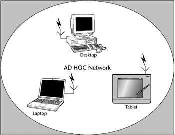
Figure 3-35: WLAN ad hoc mode.
Infrastructure Mode
Each mobile device client in infrastructure mode sends all of its communications to a network device called an access point (AP). The access point acts as a bridge does in a LAN and forwards the communications to the appropriate network, either the WLAN or another wireless network. Figure 3-36 shows access points attached to a wired LAN to create an Infrastructure Mode 802.11b WLAN.
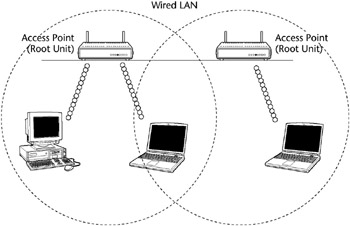
Figure 3-36: Infrastructure Mode 802.11b WLAN.
A TYPICAL BLUETOOTH SESSION
A Bluetooth-based mobile device listens to determine whether there are any other Bluetooth radios in its vicinity. If it doesn’t find any, it configures itself as the “master” device, then it configures its radio transmission to a randomly selected frequency. When another Bluetooth-enabled mobile device (say, a printer) is turned on, it searches for any other Bluetooth radio frequency transmissions in its vicinity.
When the printer finds the master device’s broadcast, it matches its transmitter to the same frequency pattern as the master device, and identifies itself to the master device. After the two devices exchange privilege and capability information, the printer becomes the “slave” of the master device’s piconet.
If a user walks into the room carrying a Bluetooth-equipped PDA and hears the master broadcast, the PDA automatically tunes its transmitter to the frequency pattern and identifies itself to the master device and becomes another slave to the master’s piconet. The three devices exchange information on each other’s access privileges and capabilities, thereby allowing the PDA to access both the desktop and the printer.
Bluetooth
Bluetooth (BT) is a simple peer-to-peer protocol created to connect multiple consumer mobile information devices (cellular phones, laptops, handheld computers, digital cameras, and printers) transparently. It uses the IEEE 802.15 specification in the 2.4 to 2.5 GHz band with FHSS technology. Bluetooth-enables mobile devices to avoid interference from other signals by hopping to a new frequency after transmitting or receiving a packet.[*]
Bluetooth is a low-power-consuming technology with transmission distances of up to 30 feet and a throughput of about 1 Mbps. The range will be extended to 300 feet by increasing the transmit power to 100 mW (milliwatts). Each Bluetooth network can accommodate only eight devices, but, thanks to frequency hopping, many Bluetooth networks can operate in the same vicinity. The Bluetooth MAC layer is TDMA-based. Bluetooth can carry either voice or low-rate data connections.
Bluetooth Security
Bluetooth’s main built-in security features are:
- Challenge-response routine. For authentication: prevents spoofing and unwanted access to critical data and functions
- Stream cipher. For encryption: prevents eavesdropping and maintains link privacy
- Session key generation. Enables session key change at any time during a connection
Three components are used in the security algorithms:
- A 48-bit Bluetooth device address, a public entity unique for each device. The address can be obtained through the inquiry (discovery) procedure.
- A private user key (128 bits), a secret entity. The private key is derived during initialization and is never disclosed.
- A random number (128 bits), different for each new transaction. The random number is derived from a pseudo-random process in the Bluetooth unit.
In addition to these link-level functions, frequency hopping and the limited transmission range also help to prevent eavesdropping. But Bluetooth PDAs are vulnerable to bluejacking, which exploits BT’s discover mode to drop code unnoticed on the victim’s unit. BT devices should be configured for non-discover mode, which limits some of its functionality but prevents bluejacking.
Wireless Application Protocol (WAP)
Wireless Application Protocol (WAP) was developed as a set of technologies related to HTML but tailored to the small screens and limited resources of handheld, wireless devices. The most notable of these technologies is the Handheld Device Markup Language (HDML). HDML looks similar to HTML but has a feature set and programming paradigm tailored to wireless devices with small screens. HDML and other elements of this architecture eventually became the Wireless Markup Language (WML) and the architecture of WAP.
Since its initial release, WAP has evolved twice. Releases 1.1 and 1.2 of the specification have the same functionality as 1.0 but with added features to align with what the rest of the industry is doing. Version 1.3 is used most often in WAP products as of this writing.
In August 2001, the WAP Forum approved and released the specifications for WAP 2.0 for public review, and Ericsson, Nokia, and Motorola all announced support for WAP 2.0. The WAP 2.0 specification contains new functionality that enables users to send sound and moving pictures, among other things, over their telephones. WAP 2.0 will also provide a toolkit for easy development and deployment of new services, including XHTML.
The WAP architecture is loosely based on the OSI model, but unlike the seven layers of OSI or the four layers of the TCP/IP model, WAP has five layers: application, session, transaction, security, and transport.
Application layer
The WAP application layer is the direct interface to the user and contains the wireless application environment (WAE). This top layer consists of several elements, including a microbrowser specification for Internet access; devices; content; the development languages Wireless Markup Language (WML) and WMLScript; wireless telephony application programming interfaces (APIs), or WTA, for accessing telephony functionality from within WAE programs;, and some well-defined content formats for phone book records, calendar information, and graphics.
Session Layer
The WAP session layer contains the Wireless Session Protocol (WSP), which is similar to the Hypertext Transfer Protocol (HTTP) because it is designed for low-bandwidth, high-latency wireless networks. WSP facilitates the transfer of content between WAP clients and WAP gateways in a binary format. Additional functionalities include content push and the suspension/resumption of connections.
The WSP layer provides a consistent interface to WAE for two types of session services: a connection mode and a connectionless service. This layer provides the following:
- Connection creation and release between the client and server
- Data exchange between the client and server by using a coding scheme that is much more compact than traditional HTML text
- Session suspend and release between the client and server
Transaction Layer
The WAP transaction layer provides the Wireless Transactional Protocol (WTP), which provides functionality similar to TCP/IP in the Internet model. WTP is a lightweight transactional protocol that provides reliable request and response transactions and supports unguaranteed and guaranteed push.
WTP provides transaction services to WAP. It handles acknowledgments so that users can determine whether a transaction has succeeded. It also provides a retransmission of transactions in case they are not successfully received, and it removes duplicate transactions. WTP manages different classes of transactions for WAP devices - unreliable one-way requests, reliable one-way requests, and reliable two-way requests. An unreliable request from a WAP device means that no precautions are taken to guarantee that the request for information makes it to the server.
Security Layer
The security layer contains Wireless Transport Layer Security (WTLS). WTLS is based on Transport Layer Security (TLS, similar to the Secure Sockets Layer, or SSL) and can be invoked in a manner similar to HTTPS in the Internet world. It provides data integrity, privacy, authentication, and DoS protection mechanisms. See the section following for more detail on the function of WTLS.
WAP privacy services guarantee that all transactions between the WAP device and gateway are encrypted. Authentication guarantees the authenticity of the client and application server. DoS protection detects and rejects data that comes in the form of unverified requests.
Transport Layer
The bottom WAP layer, the transport layer, supports the Wireless Datagram Protocol (WDP), which provides an interface to the bearers of transportation. It supports the CDPD, GSM, Integrated Digital Enhanced Network (iDEN), CDMA, TDMA, SMS, and FLEX protocols.
WDP provides a consistent interface to the higher layers of the WAP architecture, meaning that it does not matter on which type of wireless network the application is running. Among other capabilities, WDP provides data error correction. The bearers, or wireless communications networks, are at WAP’s lowest level.
Figure 3-37 shows the layers of WAP.
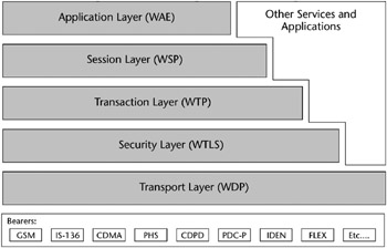
Figure 3-37: The Wireless Application Protocol.
[*]A pioneer in spread-spectrum technology was Hedy Kiesler Markey, better known as the film actress Hedy Lamarr; see www.inventions.org/culture/female/lamarr.html.
[*]Excerpted from: Wireless Security Essentials, Russell Dean Vines (Wiley, 2002).
Wireless Security
Wireless is one of the newest communications technology frontiers, offering the possibility of always-on, instant mobile communications. However, the vulnerabilities inherent to wireless computing present daunting hurdles. These vulnerabilities - eavesdropping, session hijacking, and data alteration and manipulation, in conjunction with an overall lack of privacy - are major challenges posed by wireless technologies.
Typically, when a new technology emerges, standards are created and a rush commences to develop the technology without a thorough security vetting. This has been the case with wireless, too. The result is that much work is now devoted to retrofitting security into the existing models and protocols and designing new models and protocols with better security features. Progress is being made, as standards such as 802.1x and newer versions of WAP show. Network infrastructure design, such as implementation of VPNs and RADIUS, also can help create secure pipes for wireless sessions.
Wireless Transport Layer Security Protocol
The Wireless Transport Layer Security Protocol (WTLS) is WAP’s communications security protocol. It operates above the Transport Protocol layer and provides the upper-level layer of the WAP with a secure transport service interface. The interface preserves the transport interface below it and presents methods to manage secure connections. The primary purpose of the WTLS is to provide privacy, data integrity, and authentication for WAP applications to enable safe connections to other clients.
The WTLS supports a group of algorithms to meet privacy, authentication, and integrity requirements.
Currently, privacy is implemented using block ciphers, such as DES-CBC, IDEA, and RC5-CBC. RSA- and Diffie-Hellman–based key exchange suites are supported to authenticate the communicating parties. Integrity is implemented with SHA-1 and MD5 algorithms.
For secure wireless communications, the client and the server must be authenticated and the connection encrypted. WTLS provides three classes of security:
- Class 1: Anonymous Authentication. In this mode, the client logs on to the server, but neither the client nor the server can be certain of the other’s identity.
- Class 2: Server Authentication. The server is authenticated to the client, but the client is not authenticated to the server.
- Class 3: Two-Way Client and Server Authentication. The server is authenticated to the client, and the client is authenticated to the server.
WTLS is based on the Transport Layer Security (TLS) security layer used on the Internet but has a number of modifications to accommodate the nature of wireless networks. For one, it has been optimized for low-bandwidth networks with relatively long latency. And because of the limited processing power and memory of mobile devices, fast algorithms are implemented in the algorithm suite. In addition, restrictions on export and the using of cryptography must be observed.
The WTLS is the first attempt to provide a secure end-to-end connection for the WAP. The most common protocols, such as TLS v1.0 and SSL v3.0, were adopted as a basis of the WTLS. WTLS incorporates features such as datagram support, optimized packet size and handshake, and dynamic key refreshing.
WEP Encryption
An option in IEEE 802.11b, Wired Equivalent Privacy (WEP), uses a 40-bit shared secret key, a Rivest Code 4 (RC4) pseudorandom number generator (PRNG) encryption algorithm, and a 24-bit initialization vector (IV) to provide data encryption. The basic process works as follows:
- A checksum of the message is computed and appended to the message.
- A shared secret key and the IV are fed to the RC4 algorithm to produce a key stream.
- An exclusive OR (XOR) operation of the key stream with the message and checksum grouping produces ciphertext.
- The IV is appended to the ciphertext to form the encrypted message, which is sent to the intended recipient.
- The recipient, who has a copy of the same shared key, uses it to generate an identical key stream.
- XORing the key stream with the ciphertext yields the original plaintext message.
You can find more details about WEP in Chapter 4, “Cryptography.”
Wireless Vulnerabilities
Many vulnerabilities exist in wireless networks; let’s look at a few.
Denial-of-Service Attacks
A denial-of-service (DoS) attack is an example of the failure of the tenet of availability. A DoS attack occurs when an adversary causes a system or a network to become unavailable to legitimate users or causes services to be interrupted or delayed. Consequences can range from a measurable reduction in performance to the complete failure of the system. An example from the wireless world could be an external signal jamming the wireless channel.
There is little that can be done to keep a determined adversary from mounting a DoS attack, because, as noted, wireless LANs are susceptible to interference and interception and hence often can be easily jammed. If an attacker makes use of a powerful transceiver, enough interference can be generated to prevent wireless devices from communicating with one another. DoS attack devices do not have to be next to the devices being attacked, either; they need only to be within range of the wireless transmissions.
Examples of techniques used to deny service to a wireless device are:
- Requests for authentication at such a frequency as to disrupt legitimate traffic.
- Requests for deauthentication of legitimate users. These requests may not be refused according to the current 802.11 standard.
- Mimicking the behavior of an access point and convincing unsuspecting clients to communicate with it.
- Repeatedly transmitting RTS/CTS frames to silence the network.
The 2.4 GHz frequency range, within which 802.11b operates, is shared with other wireless devices such as cordless telephones, baby monitors, and Bluetooth-based devices. All of these devices can contribute to the degradation and interruption of wireless signals. In addition, a determined and resourceful attacker with the proper equipment can flood the frequency with artificial noise and completely disrupt wireless network operation.
The “WAP Gap”
A specific security issue that is associated with WAP is the “WAP gap.” A WAP gap results from the requirement to change security protocols at the carrier’s WAP gateway from the wireless WTLS to SSL for use over the wired network. At the WAP gateway, the transmission, which is protected by WTLS, is decrypted and then re-encrypted for transmission using SSL. Thus, the data is temporarily in the clear on the gateway and can be compromised if the gateway is not adequately protected (see Figure 3-38).
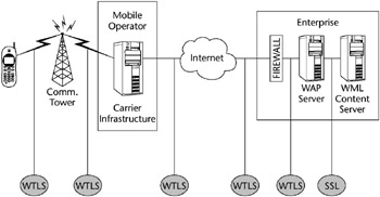
Figure 3-38: A WAP gateway.
In order to address this issue, the WAP Forum has put forth specifications that will reduce this vulnerability and thus support e-commerce applications. These specifications are defined in WAP 1.2 as WMLScript Crypto Library and the WAP Identity Module (WIM). The WMLScript Crypto Library supports end-to-end security by providing for cryptographic functions to be initiated on the WAP client from the Internet content server. These functions include digital signatures originating with the WAP client and encryption and decryption of data. The WIM is a tamper-resistant device, like a smart card, that cooperates with WTLS and provides cryptographic operations during the handshake phase.
Take special precautions to avoid the compromise of sensitive information caused by the WAP gap. WAP-enabled PEDs should not use commercial wireless network service provider gateways to access company Web servers unless end-to-end data encryption is provided.
However, the safest implementation of a WAP gateway is for companies to install the gateway in their own networks. A company WAP gateway reduces the risk of data compromise because the WTLS-to-SSL conversion required to access company Web servers would occur on a company-controlled and protected network, and connections may be monitored by IDS.
Insertion Attacks
In an insertion attack, unauthorized devices are deployed to gain access to an existing network. Laptops or PDAs can be configured to attempt access to networks simply by installing wireless network cards and setting up near a target network. If password authentication is not enabled on the network, it’s a simple matter to get a connection to an access point and network resources.
Rogue Access Points
An insertion attack could be facilitated by the deployment of rogue access points, either by a hacker or by well-meaning internal employees seeking to enhance wireless coverage. Hacker-controlled access points can be used to entice authorized wireless clients to connect to a hacker’s access point rather than to the network’s intended access points. In addition, access points not authorized by the network administrator have the potential to be improperly configured and thus vulnerable to outside attack. This raises the risk of the interception of login IDs and passwords for future direct attacks on a network. The risk can be magnified if rogue access points are deployed behind the corporate firewall.
Typically, an access point has one or several methods available to control access to a wireless LAN, typically including use of a common SSID, to allow access based on a MAC address, and WEP. Because the default authentication in 802.11 is open authentication, most systems will authenticate any user who requests connection. Shared key authentication is described but not mandated in 802.11, and it can be defeated.
Another common issue with 802.11b networks is that the access points have been designed for easy installation. So, although security features may be present, in most cases the default settings are for the features to be turned off so that the network can be up and running as quickly as possible. Network administrators who leave their equipment with the default settings intact are particularly vulnerable, as hackers are likely to try known passwords and settings when attempting to penetrate wireless networks.
Also, even when password authentication is implemented on wireless network access points, unauthorized access is still possible through the use of brute-force dictionary attacks. Password-cracking applications can methodically test passwords in an attempt to break into a network access point.
WEP Weaknesses
Most WEP products implement a 64-bit shared key, using 40 bits of this for the secret key and 24 bits for the initialization vector. The key is installed at the wired network AP and must be entered into each client as well.
WEP was not designed to withstand a directed cryptographic attack. WEP has well-known flaws in the encryption algorithms used to secure wireless transmissions. Two programs capable of exploiting the RC4 vulnerability - AirSnort and WEPCrack - both run under Linux, and both require a relatively small amount of captured data.
A number of researchers have investigated attacks on WEP:
- University of California, Berkeley, and Zero-Knowledge Systems researchers released a paper outlining the vulnerability of key stream reuse caused by the mismanagement of IVs. In their paper it was noted that all possible IVs could be exhausted in as little as five hours.
- A paper written in 2000 by Scott Fluhrer, Itsik Mantin, and Adi Shamir exposed two significant weaknesses of RC4 in the key scheduling algorithm (KSA). They found that a small portion of the secret key determines a large portion of the initial KSA output, and the secret key can be easily derived by looking at the key stream used with multiple IVs.
- Rice University and AT&T Lab researchers put the Fluhrer theory into practice by cracking encrypted packets and successfully demonstrating the severity of the flaw.
- In 2001, Nikita Borisov and a group of researchers from the University of California, Berkeley, published a paper regarding weaknesses in the WEP RC4 stream cipher. They found that if two messages used the same key stream, it may reveal information about both messages.
- Adam Stubblefield, an intern at AT&T Labs, was the first person to implement the Fluhrer attack. He noted that an extra 802.2 header is added in IP traffic, making the attack easier, because every IP packet has the same first plaintext byte.
WEP Encryption Workarounds
To address WEP encryption issues, some vendors have implemented several enhanced 802.11b security methods, such as:
- Secure key derivation. The original shared secret secure key derivation is used to construct responses to the mutual challenges. It undergoes irreversible one-way hashes that make password-replay attacks impossible. The hash values sent over the wire are useful for one time at the start of the authentication process, but never again.
- Initialization vector changes. The Cisco Aironet wireless security solution also changes the initialization vector (IV) on a per-packet basis so that hackers can find no predetermined sequence to exploit. This capability, coupled with the reduction in possible attack windows, greatly mitigates exposure to hacker attacks due to frequent key rotation. In particular, this makes it difficult to create table-based attacks based on the knowledge of the IVs seen on the wireless network.
- Dynamic WEP Keys. Several vendors are offering products that eliminate the use of static keys and instead implement per-user/per-session keys combined with RADIUS authentication. Clients must authenticate with a RADIUS server using network credentials, and WEP keys are dynamically distributed securely to the client.
Service Set Identifier (SSID) Issues
The service set identifier (SSID) is an identification value programmed in the access point or group of access points to identify the local wireless subnet. This segmentation of the wireless network into multiple networks is a form of an authentication check. If a wireless station does not know the value of the SSID, access is denied to the associated access point. When a client computer is connected to the access point, the SSID acts as a simple password, which provides a measure of security.
The wireless access point is configured to broadcast its SSID. When enabled, any client without a SSID is able to receive it and have access to the access point. Users are also able to configure their own client systems with the appropriate SSID because they are widely known and easily shared. A problem caused by the fact that most access points broadcast the SSID in their signals is that several of these access points use default SSIDs provided by the manufacturers, and a list of those default SSIDs is available for download on the Internet. This means that it’s very easy for a hacker to determine an access point’s SSID and gain access to it via software tools.
Wireless Scanning and Eavesdropping
Wireless technology is also vulnerable to eavesdropping, especially because intruders do not have to physically tap into a network. Whether on a different floor, across the room, or outside the building, an intruder can passively “sniff” your network traffic without gaining physical access as long as he or she has a WLAN card that has a promiscuous mode (that is, has the capability to capture every packet on the segment of the LAN). Covert monitoring of wireless LANs is simple. Unless specifically configured to prevent another WLAN device from joining the network, a WLAN device will accept communications from any device within its range.
Furthermore, the 802.11 protocol inherently leaves the Physical Layer header unencrypted, providing critical information to the attacker. Therefore, data encryption is the critical layer of defense, but often data is transmitted unencrypted. Using wireless packet sniffers, an attacker can passively intercept wireless network traffic and, through packet analysis, determine login IDs and passwords, as well as other sensitive data.
War Driving
War driving (also war walking) is a term used to describe a hacker who, armed with a laptop and a wireless adapter card, and traveling via a car, bus, subway train, or other form of transport, goes around sniffing for WLANs.
The concept of war driving is simple: Using a device capable of receiving an 802.11b signal, a device capable of locating itself on a map, and software that will log data from the second when a network is detected by the first, the hacker moves from place to place, letting these devices do their job. Over time, the hacker builds up a database comprising the network name, signal strength, location, and ip/namespace in use. Via SNMP, the hacker may even log packet samples and probe the access point for available data. The hacker may also mark the location of the vulnerable wireless network with chalk on the sidewalk or building itself. This is called war chalking and alerts other intruders that an exposed WLAN is nearby.
Common war driving exploits find many wireless networks with WEP disabled and using only the SSID for access control. And, as noted earlier, the SSID for wireless networks can be found quickly. This vulnerability makes these networks susceptible to what’s called the parking lot attack, in which, at a safe distance from the building’s perimeter, an attacker gains access to the target network.
Wireless Packet Sniffers and Scanners
Wireless packet analyzers, or sniffers, basically work the same way as wired network packet analyzers: They capture packets from the data stream and allow the user to open them up and look at, or decode, them. Some wireless scanners don’t employ full decoding tools but show existing WLANs and SSIDs.
A few of the wireless sniffers available are:
- AirMagnet. AirMagnet is a wireless tool originally developed for WLAN inventory, but it has developed into a useful wireless security assessment utility.
- NetStumbler. NetStumbler is a shareware program for locating WLAN SSIDs. It attempts to identify the WLAN vendor, and, when coupled with a GPS, NetStumbler can provide directional information.
- AiroPeek. WildPackets’ AiroPeek is a packet analyzer for IEEE 802.11b wireless LANs, supporting all higher-level network protocols such as TCP/IP, AppleTalk, NetBEUI, and IPX. AiroPeek is used to isolate security problems by decoding 802.11b WLAN protocols and by analyzing wireless network performance with an identification of signal strength, channel, and data rates.
- Sniffer Wireless. McAfee Sniffer Wireless is also a packet analyzer for managing network applications and deployments on Wireless LAN 802.11a and 802.11b networks. It has the ability to decrypt WEP-based traffic.
PDA Security Issues
PDAs have not been designed to the same standards nor exposed to the same rigorous examination as desktop operating systems, such as the functional requirements spelled out in the ISO standard 15408, the Common Criteria. When compared with the OS against security requirements described in these and other standards, most PDAs receive a very poor rating.
- PDA operating systems do not have provisions to separate one user’s data from another, which are required to support Discretionary Access Control (DAC).
- They lack audit capabilities.
- They have no support for object reuse control through the implementation of Identification and Authentication (I&A).
- They do not provide data integrity protection.
- Even when the OS is password-locked, applications can be installed onto the PalmOS without the owner’s knowledge.
Loss of Confidentiality
Even if a PDA is password-protected, a malicious user can retrieve the password of a target PDA by using the Palm debug mode. The password can then be decoded by using simple tools such as the PalmCrypt tool.
Once the password has been bypassed, all of the information on the PDA is fully readable by the malicious user. Security administrators currently do not have the ability to determine whether this type of attack has occurred, nor do they have any method to determine who was responsible for the attack.
Physical Loss of Unit
Probably the most common threat to a PDA is caused by the physical loss of the device. Although some technical solutions are available to protect against some of the OS security deficiencies we just mentioned, none provide a countermeasure to the physical security concerns associated with the use of PDAs. The devices are so small and portable that the loss of the device and any information contained on it is common. They are smaller and lighter, and their mode of use puts them at a greater risk because they are generally used in uncontrolled environments.
WIFI BEST PRACTICES
Wireless best practices are similar to the recommendations for a wired network. These include:
- Change the access point’s default SSID.
- Disable the “Broadcast SSID” function on the AP.
- Enable WEP and the stronger 104-bit encryption, not the breakable 40-bit.
- Employ MAC address filtering.
- Implement a RADIUS or Kerberos server to provide strong authentication.
- Physically locate the AP in an area that limits its radio emanations.
- Logically put the AP in a DMZ with the firewall between the DMZ and the internal network.
- Implement VPN tunnels.
- Disable DHCP and assign static IP addresses.
- Penetration test regularly.
- Research migrating to 802.11i technologies.
- Change the AP’s default admin password. (We shouldn’t even have to tell you this!)
Intrusion Detection and Response
The number of reported computer intrusion incidents is constantly on the rise, from 9,859 in 1999 to 82,094 in 2002.[*] Intrusion Detection (ID) and Response is the task of monitoring systems for evidence of an intrusion or an inappropriate usage and responding to the intrusion. ID is the detection of inappropriate, incorrect, or anomalous activity. ID is not a preventative control; it is a detective control.
Types of Intrusion Detection Systems
ID systems that operate on a specific host and detect malicious activity only on that host are called host-based ID systems. ID systems that operate on network segments and analyze that segment’s traffic are called network-based ID systems. Since there are pros and cons to each, an effective IDS should use a combination of both network- and host-based intrusion detection systems.
Host-Based ID Systems
Host-based ID systems employ small software programs called intelligent agents. They reside on a host computer, monitor the operating system, and continually write to log files and trigger alarms. They detect inappropriate activity only on the host computer; they do not monitor the entire network segment.
Host-based ID systems:
- Monitor accesses and changes to critical system files and changes in user privileges
- Detect trusted-insider attacks better than network-based IDS
- Are relatively effective for detecting attacks from the outside
- Can be configured to look at all network packets, connection attempts, or login attempts to the monitored machine, including dial-in attempts or other non-network–related communication ports
Network-Based ID Systems
Network-based ID systems commonly reside on a discrete network segment and monitor the traffic on that network segment. They usually consist of a network appliance with a NIC that is operating in promiscuous mode and is intercepting and analyzing the network packets in real time.
Network-based ID involves looking at the packets on the network as they pass by some sensor. The sensor can see only the packets that happen to be carried on the network segment it’s attached to. Network traffic on other segments, and traffic on other means of communication (such as phone lines), can’t be monitored properly by network-based IDS.
Packets are identified to be of interest if they match a signature. Three primary types of signatures are:
- String signatures - String signatures look for a text string that indicates a possible attack.
- Port signatures - Port signatures watch for connection attempts to well known, frequently attacked ports.
- Header condition signatures - Header signatures watch for dangerous or illogical combinations in packet headers.
IDS Approaches
The most common approaches to ID are statistical anomaly (also known as behavior-based) detection and pattern-matching (also known as knowledge-based or signature-based) detection.
Knowledge-Based ID
Knowledge-based ID systems use a database of previous attacks and known system vulnerabilities to look for current attempts to exploit these vulnerabilities, and then they trigger an alarm if an attempt is found. Most IDSs today are knowledge-based, and the accuracy of knowledge-based intrusion detection systems is considered good.
The advantages of a knowledge-based ID system are:
- System is characterized by low false alarm rates (positives).
- Alarms are standardized and are clearly understandable by security personnel.
The disadvantages of knowledge-based ID systems are:
- System is resource-intensive. The knowledge database continually needs maintenance and updating with new vulnerabilities and environments to remain accurate.
- Since knowledge about attacks is very focused (dependent on the operating system, version, platform, and application), new, unique, or original attacks often go unnoticed.
- Detection of insider attacks involving an abuse of privileges is deemed more difficult because no vulnerability is actually exploited by the attacker.
Behavior-Based ID
Behavior-based ID systems dynamically detect deviations from the learned patterns of user behavior, and an alarm is triggered when an activity that is considered intrusive (outside of normal system use) occurs. Behavior-based ID systems are less common than knowledge-based ID systems.
Behavior-based ID systems learn the normal or expected behavior of the system or the users and assume that an intrusion can be detected by observing deviations from this norm.
The advantages of behavior-based ID systems are:
- They dynamically adapt to new, unique, or original vulnerabilities.
- They are not as dependent upon specific operating systems as knowledge-based ID systems.
- They help detect abuse-of-privileges types of attacks that do not actually involve exploiting any security vulnerability.
The disadvantages of behavior-based ID systems are:
- Characterized by high false alarm rates. High positives are the most common failure of behavior-based ID systems and can create data noise that can make the system unusable or difficult to use.
- Activity and behavior of the users while in the networked system may not be static enough to effectively implement a behavior-based ID system.
- The network may experience an attack at the same time the intrusion detection system is learning the behavior.
Honey Pots
A honey pot is a system on the network intentionally configured to lure intruders. Honey pots simulate one or more network services, hoping that an attacker will attempt an intrusion. Honey pots are most successful when run on known servers, such as HTTP, mail, or DNS servers, because these systems advertise their services and are often the first point of attack. They are often used to augment the deployment of an IDR system.
A honey pot is configured to interact with potential hackers in such a way as to capture the details of their attacks. These details can be used to identify what the intruders are after, their skill level, and what tools they use.
Honey pots should be physically isolated from the real network and are commonly placed in a DMZ. All traffic to and from the honey pot should also be routed through a dedicated firewall.
A honey pot is usually configured by installing the operating system using defaults, no patches, and the application designed to record the activities of the intruder.
Evidence of an intrusion into a honey pot can be collected through:
- The honey pot’s firewall logs
- The honey pot’s system logs
- Intrusion detection systems or other monitoring tools
A properly configured honey pot monitors traffic passively, doesn’t advertise its presence, and provides a preserved prosecution trail for law enforcement agencies.
Honey Pot Issues
It’s important to be aware of legal issues arising out of implementing a honey pot. Some organizations discourage the use of honey pots, citing the legal concerns of luring intruders, and feel that no level of intrusion should be encouraged.
Before the intrusion occurs, it’s advisable to consult with local law enforcement authorities to determine the type and amount of data they will need in order to prosecute and how to properly preserve the chain of evidence.
Also, because the honey pot must be vigilantly monitored and maintained, some organizations feel it is too resource-intensive for practical use.
Computer Incident Response Team
Response includes notifying the appropriate parties to take action in order to determine the extent of the severity of an incident and to remediate the incident’s effects. According to NIST, an organization should address computer security incidents by developing an incident-handling capability. The incident-handling capability should be used to:
- Provide the ability to respond quickly and effectively.
- Contain and repair the damage from incidents. When left unchecked, malicious software can significantly harm an organization’s computing resources, depending on the technology and its connectivity. Containing the incident should include an assessment of whether the incident is part of a targeted attack on the organization or is an isolated incident.
- Prevent future damage. An incident-handling capability should assist an organization in preventing (or at least minimizing) damage from future incidents. Incidents can be studied internally to gain a better understanding of the organization’s threats and vulnerabilities.
As part of a structured incident-handling program of Intrusion Detection and Response, a Computer Emergency Response Team (CERT) or Computer Incident Response Team (CIRT) is commonly created. Because “CERT” refers specifically to the CERT Coordination Center located at Carnegie Mellon’s Software Engineering Institute (SEI), “CIRT” is used more often.
The main tasks of a CIRT are:
- Analysis of an event notification
- Response to an incident if the analysis warrants it
- Escalation path procedures
- Resolution, post-incident follow-up, and reporting to the appropriate parties
The prime directive of every CIRT is Incident Response Management, which manages a company’s response to events that pose a risk to its computing environment. This management often consists of the following:
- Coordinating the notification and distribution of information pertaining to the incident to the appropriate parties (those with a need to know) through a predefined escalation path
- Mitigating risk to the enterprise by minimizing the disruptions to normal business activities and the costs associated with remediating the incident (including public relations)
- Assembling teams of technical personnel to investigate the potential vulnerabilities and to resolve specific intrusions
Additional examples of CIRT activities are:
- Management of the network logs, including collection, retention, review, and analysis of data
- Management of the resolution of an incident, management of the remediation of a vulnerability, and post-event reporting to the appropriate parties
IDS and a Layered Security Approach
Computer security is most effective when multiple layers of security are used within an organization, and ID is best utilized when implemented in a layered security approach. This concept implies that multiple steps are taken to secure the data, thereby increasing the workload and time required for an intruder to penetrate the network.
Therefore, although a firewall is an excellent perimeter security device, it is just one element of an effective security strategy. The more elements, or layers, of security that can be added to protect the data, the more secure the infrastructure will remain.
Elements of an effective layered security approach include:
- Security policies, procedures, standards, and guidelines, including high-level security policy
- Perimeter security, such as routers, firewalls, and other edge devices
- Hardware and/or software host security products
- Auditing, monitoring, intrusion detection, and response
Each of these layers may be implemented independently of the others, yet they are interdependent when functioning. An IDS that alerts to unauthorized access attempts or port scanning is useless without a response plan to react to the problem. Since each layer provides elements of protection, the defeat of any one layer should not lead to a failure of protection.
IDS and Switches
One serious issue with IDS is the proper implementation of IDS sensors in a switched environment. This issue arises from the basic differences between standard hubs and switches. Hubs exclude only the port the packet came in on; otherwise, they echo every packet to every port on the hub. Therefore, in networks employing only hubs, IDS sensors can be placed almost anywhere in the infrastructure.
However, when a packet comes into a switch, a temporary connection in the switch is first made to the destination port, and then the packet is forwarded. This means more care must be exerted when placing IDS sensors in a switched environment to ensure that the sensor is able to see all of the network traffic. Figure 3-39 shows an IDS employed on its own subnet.
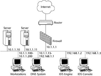
Figure 3-39: IDS on a subnet.
Some switches permit spanning port configuration, which configures the switch to behave like a hub only for a specific port. The switch can be configured to span the data from a specific port to the IDS port. Unfortunately, some switches cannot be guaranteed to pass all the traffic to the spanned port, and most switches allow only one port to be spanned at a time.
Another partial solution is to place a hub between the monitored connections, say between two switches, between a router and a switch, or between a server and a switch. This allows traffic to still flow between the switch and the target but with traffic to be copied off to the IDS. This solution, however, spells the beginning of the end for the switched network and removes the benefits of a switched solution.
IDS Performance
Another issue with the implementation of intrusion detection systems is the performance of the IDS when the network bandwidth begins to reach saturation levels. Obviously, there is a limit to the number of packets that a network intrusion detection sensor can accurately analyze in any given time period. The higher the network traffic level and the more complex the analysis, the more the IDS may experience high error rates, such as the premature discarding of copied network packets.
[*]Source: CERT Coordination Center (CERT/CC), www.cert.org.
Network Attacks and Abuses
Attacks against computers, networks, and cryptographic systems have a variety of motivations. Some attacks are aimed at disrupting service, others focus on illegally acquiring sensitive information, and others attempt to deceive or defraud. In general, such attacks target the C.I.A. components of information security. In this section the most common types of attacks on networks are explored.
The CISSP candidate will need to know, in general, the various types of attacks on and abuses of networked systems. In current practice, these attacks are constantly evolving. This is probably the most dynamic area of InfoSec today. Large teams and huge amounts of money and resources are dedicated to reacting to the latest twists and turns of intrusions into networked systems, particularly on the Internet. We describe attacks and abuses in almost every chapter; here we focus on those attacks and abuses that commonly apply to networked systems.
Logon Abuse
Logon abuse can refer to legitimate users accessing services of a higher security level that would normally be restricted to them. Unlike network intrusion, this type of abuse focuses primarily on those users who might be legitimate users of a different system or users who have a lower security classification.
Masquerading is the term used when one user pretends to be another user. An attacker socially engineering passwords from an ISP could be an example of masquerading.
Inappropriate System Use
This style of network abuse refers to the nonbusiness or personal use of a network by otherwise authorized users, such as Internet surfing to inappropriate content sites (travel, pornography, sports, and so forth). As per the (ISC) Code of Ethics and the Internet Advisory Board (IAB) recommendations, the use of networked services for other than business purposes can be considered abuse of the system. Although most employers do not enforce extremely strict Web surfing rules, occasional harassment litigation resulting from employees accessing pornography sites and employees operating private Web businesses using the company’s infrastructure can constitute unauthorized use.
Eavesdropping
This type of network attack consists of the unauthorized interception of network traffic. Certain network transmission methods, such as satellite, wireless, mobile, PDA, and so on, are vulnerable to eavesdropping attacks. Tapping refers to the physical interception of a transmission medium (such as the splicing of a cable or the construction of an induction loop to pick up electromagnetic emanations from copper).
- Passive Eavesdropping - Covertly monitoring or listening to transmissions without authorization from either the sender or the receiver
- Active Eavesdropping - Tampering with a transmission to create a covert signaling channel, or actively probing the network for infrastructure information
Eavesdropping and probing are often the preliminary steps to session hijacking and other network intrusions. Covert channel eavesdropping refers to using a hidden, unauthorized network connection to communicate unauthorized information. A covert channel is a connection intentionally created to transmit unauthorized information from inside a trusted network to a partner at an outside, untrusted node. Covert channels are described in more detail in Chapter 6, “Operations Security.”
As previously noted, war walking (or war driving) refers to scanning for 802.11-based wireless network information by either driving or walking with a laptop, a wireless adapter in promiscuous mode, some type of scanning software such as NetStumbler or AiroPeek, and a Global Positioning System (GPS).[*]
Network Intrusion
This type of attack refers to the use of unauthorized access to break into a network primarily from an external source. Unlike a logon abuse attack, the intruders are not considered to be known to the company. Most common conceptions of hacks reside in this category. Also known as a penetration attack, it exploits known security vulnerabilities in the security perimeter.
Back doors are very hard to trace, as an intruder will often create several avenues into a network to be exploited later. The only real way to be sure these avenues are closed after an attack is to restore the operating system from the original media, apply the patches, and restore all data and applications.
Piggybacking in the network domain refers to an attacker gaining unauthorized access to a system by using a legitimate user’s connection. A user may leave a session open or log off incorrectly, enabling an unauthorized user to resume the session.
Denial of Service (DoS) Attacks
The DoS attack might use some of the following techniques to overwhelm a target’s resources:
- Filling up a target’s hard drive storage space by using huge e-mail attachments or file transfers
- Sending a message that resets a target host’s subnet mask, causing a disruption of the target’s subnet routing
- Using up all of a target’s resources to accept network connections, resulting in additional network connections being denied
Specific DoS attacks are discussed in Chapter 2, “Access Control.”
Session Hijacking Attacks
Unauthorized access to a system can be achieved by session hijacking. In this type of attack, an attacker hijacks a session between a trusted client and network server. The attacking computer substitutes its IP address for that of the trusted client, and the server continues the dialog believing it is communicating with the trusted client.
Some examples of session highjacking attacks are:
- IP Spoofing Attacks. IP spoofing involves an alteration of a packet at the TCP level. The attacker sends the target host a packet with the IP source address set to that of a known, trusted host. This target host may accept the packet and act upon it. Unlike a Smurf attack (described in Chapter 2), where spoofing creates a DoS attack, here IP spoofing convinces a system that it is communicating with a known entity and so give an intruder access.
- C2MYAZZ. C2MYAZZ is a utility that enables server spoofing to implement a session hijacking or man-in-the-middle exploit (see Chapter 2). It intercepts a client LANMAN authentication logon and obtains the session’s logon credentials and password combination, transparently to the user.
- TCP Sequence Number Attacks. TCP sequence number attacks exploit the communications session that was established between the target and the trusted host that initiated the session. The intruder tricks the target into believing it is connected to a trusted host and then hijacks the session by predicting the target’s choice of an initial TCP sequence number. This session is then often used to launch various attacks on other hosts.
- DNS poisoning. Domain Name Service (DNS) poisoning is also known as cache poisoning. It is the process of distributing incorrect IP address information for a specific host with the intent to divert traffic from its true destination.
Fragmentation Attacks
IP fragmentation attacks use varied IP datagram fragmentation to disguise their TCP packets from a target’s IP filtering devices. Two examples of these types of attacks are:
- A tiny fragment attack occurs when the intruder sends a very small fragment that forces some of the TCP header field into a second fragment. If the target’s filtering device does not enforce minimum fragment size, this illegal packet can then be passed on through the target’s network.
- An overlapping fragment attack is another variation on a datagram’s zero-offset modification (like the teardrop attack). Subsequent packets overwrite the initial packet’s destination address information, and then the second packet is passed by the target’s filtering device. This can happen if the target’s filtering device does not enforce a minimum fragment offset for fragments with nonzero offsets.
We describe various TCP fragmentation attacks later in the chapter.
Dial Up Attacks
- War dialing. War dialing is a method used to hack into computers by using a software program to automatically call a large pool of telephone numbers to search for those that have a modem attached.
- Demon dialing. Demon dialing, similar to war dialing, is a tool used to attack one modem using brute force to guess the password and gain access.
- ToneLoc. ToneLoc was one of the first war-dialing tools used by “phone phreakers.”[*]
[*]Source: “War Driving by the Bay,” by Kevin Poulsen, The Register, April 13, 2001.
[*]Source: Hacking Exposed, Stuart McClure, Joel Scambray, and George Kurtz (Osborne, 1999).
Probing and Scanning
Probing is an active variation of eavesdropping, usually used to give an attacker a road map of the network in preparation for an intrusion or a DoS attack. Attackers use it to discover what ports are open, what services are running, and what system software is being used. Probing enables an attacker to more easily detect and exploit known vulnerabilities within a target machine.
Scanning, or traffic analysis, uses a “sniffer” to scan the hosts of various enabled services to document what systems are active on a network and what ports are open.
Both of these can be performed either manually or automatically. Manual vulnerability checks are performed using tools such as Telnet to connect to a remote service to see what is listening. Automated vulnerability scanners are software programs that automatically perform all the probing and scanning steps and report the findings back to the user. As a result of the free availability of such software on the Internet, the amount of this type of automated probing has increased.
Vulnerability Scanning
Vulnerability scanning should be implemented by the security professional to help identify weaknesses in a system. It should be conducted on a regular periodic basis to identify compromised or vulnerable systems. The scans directed at a target system can either be internal, originating from within the system, or external, originating from outside the target system.
Because scanning activity is often a prelude to a system attack, monitoring and analysis of the logs and blocking of unused and exposed ports should accompany the detection of malicious scans.
Conducting scans inside the enterprise on a regular basis is one way to identify and track several types of potential problems, such as unused ports that respond to network requests. Also, uncontrolled or unauthorized software may be located using these scanning techniques.
A common vulnerability-scanning methodology may employ several steps, including an IP device discovery scan, workstation vulnerability scan, and server vulnerability scan.
Discovery Scanning
The intent of a discovery scan is to collect enough information about each network device to identify what type of device it is (e.g., workstation, server, router, firewall), its operating system, and whether it is running any externally vulnerable services such as Web services, FTP, or e-mail. The discovery scan contains two elements: inventory and classification. The inventory scan provides information about the target system’s operating system and its available ports. The classification process identifies applications running on the target system, which aids in determining the device’s function.
Workstation Scanning
A full workstation vulnerability scan of the standard corporate desktop configuration should be implemented regularly. This scan helps ensure that the standard software configuration is current with the latest security patches and software, and it helps locate uncontrolled or unauthorized software.
Server Scanning
A full server vulnerability scan will determine whether the server OS has been configured to the corporate standards and whether applications are kept current with the latest security patches and software. All services must be inspected for elements that may compromise security, such as default accounts and weak passwords. Also, unauthorized programs such as Trojans may be identified.
Port Scanning
Port scanning is the process of sending a data packet to a port to gather information about the state of the port. This is also called a probe. Port scanning makes it possible to find what TCP and UDP ports are in use. For example, if ports 25, 80, and 110 are open, the device is running the SMTP, HTTP, and POP3 services.
A cracker can use port-scanning software to determine which hosts are active and which are inactive (down) in order to avoid wasting time on inactive hosts. A port scan can gather data about a single host or hosts within a subnet (256 adjacent network addresses).
A scan may first be implemented using the ping utility. Then, after determining which hosts and associated ports are active, the cracker can initiate different types of probes on the active ports.
Examples of probes are:
- Gathering information from the Domain Name Service (DNS)
- Determining the network services that are available, such as e-mail, FTP, and remote logon
- Determining the type and release of the operating system
TCP/UDP Scanning Types
Many types of TCP/UDP scanning techniques exist. Some are simple and easily detectable by firewalls and intrusion detection systems, whereas some are more complicated and harder to detect.
Stealth Scans
Certain types of scans are called stealth scans because they try to evade or minimize their chances of detection. Several of the scans outlined later, such as the TCP SYN or TCP FIN scan, can be described as stealth scans.
Another example of a stealth scan is implemented through fragmenting the IP datagram within the TCP header. This will bypass some packet filtering firewalls because they don’t get a complete TCP header to match the filter rules.
Spoofed Scans
Although the term spoofing comes up often in any discussion of security, it can be applied here to conceal the true identity of an attacker. Spoofing allows an attacker to probe the target’s ports without revealing the attacker’s own IP address. The FTP proxy bounce attack described subsequently is an example of a spoofed scan that compromises a third-party FTP server.
The HPing network analysis tool, also described later, hides the source of its scans by using another host through which to probe the target site. Also, NMap provides spoofing capability by allowing the operator to enter an optional “source” address for the scanning packet.
The following are some TCP-based scanning techniques:
- TCP connect(). Connect() is the most basic and fastest scanning technique. Connect() is able to scan ports quickly simply by attempting to connect to each port in succession. The biggest disadvantage for attackers is that it is the easiest to detect and can be stopped at the firewall.
- TCP SYN (half open) scanning. TCP SYN scanning is often referred to as half-open scanning because, unlike TCP connect(), a full TCP connection is never opened. The scan works as follows:
- A SYN packet is sent to a target port.
- If a SYN/ACK is received, this indicates the port is listening.
- The scanner then breaks the connection by sending an RST (reset) packet.
- If an RST is received, this indicates the port is closed.
- This is harder to trace because fewer sites log incomplete TCP connections, but some packet-filtering firewalls look for SYNs to restricted ports.
- TCP SYN/ACK scan. TCP SYN/ACK is another way to determine whether ports are open or closed. The TCP SYN/ACK scan works as follows:
- Scanner initially sends a SYN/ACK.
- If the port is closed, it assumes the SYN/ACK packet was a mistake and sends an RST.
- If the port is open, the SYN/ACK packet will be ignored and dropped.
- This is considered a stealth scan since it isn’t likely to be logged by the host being scanned, but many intrusion detection systems may catch it.
- TCP FIN scanning. TCP FIN is a stealth scan that works like the TCP SYN/ACK scan.
- Scanner sends a FIN packet to a port.
- A closed port replies with an RST.
- An open port ignores the FIN packet.
- One issue with this type of scanning is that TCP FIN can be used only to find listening ports on non-Windows machines or to identify Windows machines, because Windows ports send an RST regardless of the state of the port.
- TCP FTP proxy (bounce attack) scanning. TCP FTP proxy (bounce attack) scanning is a very stealthy scanning technique. It takes advantage of a weakness in proxy FTP connections. It works like this:
- The scanner connects to an FTP server and requests that the server initiate a data transfer process to a third system.
- The scanner uses the PORT FTP command to declare that the data transfer process is listening on the target box at a certain port number.
- It then uses the LIST FTP command to try to list the current directory. The result is sent over the server data transfer process channel.
- If the transfer is successful, the target host is listening on the specified port.
- If the transfer is unsuccessful, a “425 Can’t build data connection: Connection refused” message is sent.
- Some FTP servers disable the proxy feature to prevent TCP FTP proxy scanning.
- IP fragments. Fragmenting IP packets is a variation on the other TCP scanning techniques. Instead of sending a single probe packet, the packet is broken into two or more packets and reassembled at the destination, thus bypassing the packet filters.
- ICMP scanning (ping sweep). ICMP doesn’t use ports, so this is technically not a port-scanning technique, but it should be mentioned. Using ICMP Echo requests, the scanner can perform what is known as a ping sweep. Scanned hosts will reply with an ICMP Echo reply indicating that they are alive, whereas no response may mean the target is down or nonexistent.
Determining the OS Type
Determining the type of OS is also an objective of scanning, because this will determine the type of attack to be launched.
Sometimes a target’s operating system details can be found very simply by examining its Telnet banners or its File Transfer Protocol (FTP) servers, after connecting to these services.
TCP/IP stack fingerprinting is another technique to identify the particular version of an operating system. Since OS and device vendors implement TCP/IP differently, these differences can help in determining the OS.
Some of these differences include:
- Time To Live (TTL)
- Initial Window Size
- Don’t Fragment (DF) bit
- Type of Service (TOS)
Table 3-11shows some common Time To Live values. Remember that the TTL will decrement each time the packet passes through a router. This means that the TTL of a router 6 hops away will be 249 (255 – 6).
|
TIME TO LIVE |
OPERATING SYSTEM OR DEVICE TYPE |
|---|---|
|
255 |
Many network devices, Unix and Macintosh systems |
|
128 |
Many Windows systems |
|
60 |
Hewlett-Packard Jet Direct printers |
|
32 |
Some versions of Windows 95B/98 |
Another type of OS identification technique is TCP initial sequence number sampling. After the target host responds to a connection request, information about the operating system can be inferred from the pattern of the sequence numbers.
Scanning Tools
Many of these tools are used by crackers and intruders, but they also help the security administrator detect and stop malicious scans. Used with intrusion detection systems, these tools can provide some level of protection by identifying vulnerable systems, and they can provide data about the level of activity directed against a machine or network. Since scanning is a continuous activity (that is, all networked systems are being scanned all of the time), it’s very important that the security professional know what can be compromised. Some common scanning tools are:
- Computer Oracle and Password System (COPS) - examines a system for a number of known weaknesses and alerts the administrator.
- HPing - a network analysis tool that sends packets with non-traditional IP stack parameters. It allows the scanner to gather information from the response packets generated.
- Legion - will scan for and identify shared folders on scanned systems, allowing the scanner to map drives directly.
- Nessus - a free security-auditing tool for Linux, BSD, and a few other platforms. It requires a back-end server that has to run on a Unix-like platform.
- NMap - a very common port-scanning package. More information on NMap follows this section.
- Remote Access Perimeter Scanner (RAPS) - part of the corporate edition of PCAnywhere by Symantec. RAPS will detect most commercial remote control and backdoor packages such as NetBus, and it can help lock down PCAnywhere.
- Security Administrator’s Integrated Network Tool (SAINT) - examines network services, such as finger, NFS, NIS, ftp and tftp, rexd, statd, and others, to report on potential security flaws.
- System Administrator Tool for Analyzing Networks (SATAN) - is one of the oldest network security analyzers. SATAN scans network systems for well-known and often exploited vulnerabilities.
- Tcpview - will allow identification of what application opened which port on Windows platforms.
- Snort - is a utility used for network sniffing. Network sniffing is the process of gathering traffic from a network by capturing the data as it passes and storing it to analyze later.
NMap
NMap scans for most ports from 1 to 1024 and a number of others in the registered and undefined ranges. This helps identify software such as PCAnywhere, SubSeven, and BackOrifice. Now that a Windows interface has been written, it no longer has to be run only on a Unix system.
NMap allows scanning of both TCP and UDP ports, with root privilege required for UDP. While NMap doesn’t have signature or password-cracking capabilities, like L0phtcrack, it will estimate how hard it will be to hijack an open session.
Vulnerable Ports
Although the complete listing of well-known and registered ports is extensive, some ports are attacked more often than others. In Table 3-12, we’ve listed the ports that are the greatest risk to networked systems.
|
PORT # |
SERVICE NAME |
SERVICE DESCRIPTION |
|---|---|---|
|
21 |
ftp |
File Transfer Protocol |
|
23 |
telnet |
Telnet virtual terminal |
|
25,109,110 143 |
smtp, pop3, imap |
Simple Mail Protocol, POP2, POP3, and IMAP Messaging |
|
53 |
dns |
Domain Name Services |
|
80, 8000, 8080 |
http |
Hyper-Text Transfer Protocol and HTTP proxy servers |
|
118 |
sqlserv |
SQL database service |
|
119 |
nntp |
Network News Transfer Protocol |
|
161 |
snmp |
Simple Network Management Protocol |
|
194 |
irc |
Internet Relay Chat |
|
389,636 |
ldap |
Lightweight Directory Access Protocol |
|
2049 |
nfs |
Networking File Systems |
|
5631 |
PCAnywhere |
PCAnywhere Remote Control |
Issues with Vulnerability Scanning
Some precautions need to be taken when the security administrator begins a program of vulnerability scanning on his or her own network. Some of these issues could cause a system crash or create unreliable scan data.
- False positives. Some legitimate software uses port numbers registered to other software, which can cause false alarms when port scanning. This can lead to blocking legitimate programs that appear to be intrusions.
- Heavy traffic. Port scanning can have an adverse effect on WAN links and even effectively disable slow links. Because heavy port scanning generates a lot of traffic, it is usually preferable to perform the scanning outside normal business hours.
- False negatives. Port scanning can sometimes exhaust resources on the scanning machine, creating false negatives and not properly identifying vulnerabilities.
- System crash. Port scanning has been known to render needed services inoperable or actually crash systems. This may happen when systems have not been currently patched or the scanning process exhausts the targeted system’s resources.
- Unregistered port numbers. Many port numbers in use are not registered, which complicates the act of identifying what software is using them.
HOW DO WE GET WINDOWS NT PASSWORDS?
The NT Security Accounts Manager (SAM) contains the usernames and encrypted passwords of all local (and domain, if the server is a domain controller) users. The SAM uses an older, weaker LanManager hash that can be broken easily by tools such as L0phtcrack. Physical access to the NT server and the rdisks must be controlled. The “Sam” file in the repair directory must be deleted after creation of an rdisk. Pwdump and pwdump2 are utilities that allow someone with Administrator rights to target the Local Security Authority Subsystem, lsass.exe, from a remote system:
- Obtain the backup SAM from the repair directory
- Boot the NT server with a floppy containing an alternative operating system
- Use pwdump2 to dump the password hashes directly from the registry
Malicious Code
Malicious code is the name used for any program that adds to, deletes, or modifies legitimate software for the purpose of intentionally causing disruption and harm or to circumvent or subvert the existing system’s function. Examples of malicious code include viruses, worms, Trojans, and logic bombs. Newer malicious code is based on mobile ActiveX controls and Java applets.
Viruses
Viruses are a type of malicious code that attaches to a host program and propagates when an infected program is executed.
A virus infects the operating system in two ways: by completely replacing one or more of the operating system’s programs or by attaching itself to existing operating system programs and altering functionality. Once a virus has changed OS functionality, it can control many OS processes that are running.
To avoid detection, the virus usually creates several hidden files within the OS code or in “unusable” sectors. Since infections in the OS are difficult to detect, they have deadly consequences on systems relying on the OS for basic functions. Jerusalem, Cascade, and Form are some viruses that infect the boot sector.
The Virus Life Cycle
There are two main phases in the life cycle of a virus: replication and activation. In the first phase, replication, viruses typically remain hidden and do not interfere with normal system functions. During this time, viruses actively seek out new hosts to infect by attaching themselves to other software programs or by infiltrating the OS, for example.
During the second phase, activation, the virus’s payload gradually or suddenly inflicts damage on the host system. Typically, the decision to activate is based on a mathematical formula with criteria such as date, time, number of infected files, and others. The possible damage at this stage could include destroyed data, software or hardware conflicts, space consumption, and abnormal behavior.
Macro Viruses
Macro viruses are the most prevalent computer viruses in the wild, accounting for the vast majority of virus encounters. A macro virus can easily infect applications such as Microsoft Excel and Word.
To infect the system, macro viruses attach themselves to the application’s initialization sequence, and then when the application is executed, the virus’s instructions execute before control is given to the application. Thus the virus replicates itself, infecting more and more of the system. If the application has e-mail capabilities, the virus uses these to mail copies of itself to contacts it finds in the victim’s address book.
These macro viruses move from system to system through e-mail file sharing, demonstrations, data sharing, and disk sharing. Today’s widespread sharing of macro-enabled files, primarily through e-mail attachments, is rapidly increasing the macro virus threat.
Well-known macro viruses from recent years include:
- Word macros: Concept
- E-mail enabled Word macros: Melissa
- E-mail enabled Visual Basic scripts: I Love You
Polymorphic Viruses
Polymorphic viruses are difficult to detect because they hide themselves from antivirus software by altering their appearance after each infection. Some polymorphic viruses can assume over two billion different identities.
There are three main components of a polymorphic virus: a scrambled virus body, a decryption routine, and a mutation engine. The process of a polymorphic infection is:
- The decryption routine first gains control of the computer and then decrypts both the virus body and the mutation engine.
- The decryption routine transfers control of the computer to the virus, which locates a new program to infect.
- The virus makes a copy of itself and the mutation engine in RAM.
- The virus invokes the mutation engine, which randomly generates a new decryption routine capable of decrypting the virus yet bearing little or no resemblance to any prior decryption routine.
- The virus encrypts the new copy of the virus body and mutation engine.
- The virus appends the new decryption routine, along with the newly encrypted virus and mutation engine, onto a new program.
As a result, not only is the virus body encrypted, but also the virus decryption routine varies from infection to infection. No two infections look alike, confusing the virus scanner searching for the sequence of bytes that identifies a specific decryption routine.
Stealth Viruses
Stealth viruses attempt to hide their presence from both the OS and the antivirus software by:
- Hiding the change in the file’s date and time
- Hiding the increase in the infected file’s size
- Encrypting themselves
They are similar to polymorphic viruses in that they are very hard to detect.
Spyware
Generally, spyware is any technology that aids in gathering information about a person or organization without their knowledge or consent - a software category that covers any program that secretly tracks or records your personal information. There are benign versions, such as adware, which largely only irritate the user by displaying targeted ads and hogging resources. Obviously, law enforcement has a use for spyware, and employers or parents may have a legal right to know what’s going on with a PC in their business or home.
But now spyware is becoming far more dangerous than adware and can cause more long-lasting problems than most viruses. The newest versions of spyware have become remarkably self-sufficient and potent, not only accessing sensitive information stored on the computers they infect but, in some recent cases, surreptitiously intercepting financial data as it’s being transmitted. They can also auto-update themselves, alter system configurations, and download and install additional software at will.[*]
The types of information gathered by spyware can include:
- A record of the victim’s keystrokes, including financial passwords
- Web sites visited by the user
- What applications are installed
- The operating system version
- Various registry settings
Spyware comes in many flavors: some merely annoying, some dangerous, and some that lead to identity theft. Some spyware presents the user with a deceptive pop-up window to trick the user into accepting its installation. Other types, such as drive-by downloads, don’t even need your consent or knowledge to jump onto your machine.
IN THE BEGINNING
The word spyware first surfaced in a Usenet post in October 1995. The post was making fun of the Microsoft business model and inferred that some elements of Windows were designed to keep an eye on users’ computing behavior. Zone Labs, the company that makes the Zone Alarm Personal Firewall, then used the term in a press release in 1999. It’s been in the lexicon ever since.
Adware
Adware is software designed to serve advertising and marketing. It qualifies as spyware because it almost invariably includes components for tracking and reporting user information; the user may or may not know it’s even there.
Keyloggers
Keyloggers are a form of spyware that records user keystrokes. They can be either hardware devices or software programs. They record every key typed on a computer, sending this information to the person who installed it or saving it to be read later.
The software versions may be delivered by Trojan horse e-mail attachments or installed directly to the PC. The hardware version must be physically installed on the target machine, usually without the user’s knowledge. Although keyloggers are sometimes used in the payloads of viruses, they are more commonly delivered by a Trojan horse program or remote access Trojan (RAT), discussed later.
Since keylogging programs record every keystroke typed in via the keyboard, they can capture a wide variety of confidential information, including passwords, credit card numbers, private e-mail correspondence, names, addresses, phone numbers, and other sensitive documents. Sometimes these logging files are e-mailed to the person who planted the logging software. On PCs accessed by the public in areas such as copy shops, cyber cafes, and university computer labs, the spy simply accesses the log file from the compromised machine at a later date.
Once installed on the target machine, either direct through interaction with the user or through a more stealthy means, the keylogger program runs continually in the background. After the keystrokes are logged, they can be hidden in the machine for later retrieval or transmitted to the attacker via the Internet.
The attacker then examines the reports for passwords or information that can be used to compromise the system or engineer an attack. A keylogger may reveal the contents of e-mail composed by the victim.
Some rare keyloggers include routines that secretly turn on video or audio recorders and transmit what they capture over your Internet connection. Other products, such as Spector and PCSpy, capture screens rather than keystrokes. However, most criminal keyloggers are hoping to steal bank account numbers or other financial data.
As an example, look at everything one commercial software keylogger, ISpyNow, claims it can do:
- Logs all Web sites visited
- Records all keystrokes, including hidden system keys
- Records information on which windows have been opened
- Logs every application executed
- Records both ends of AIM/AOL/MSN/ICQ instant messaging in real time
- Records all text and images cut and pasted to the Clipboard
Hardware Keyloggers
Some hardware keystroke loggers consist of an AA battery-sized plug that connects between the victim’s keyboard and computer. The device collects each keystroke as it is typed and saves it in a text file on its own tiny hard drive. Later, the keystroke logger owner returns, removes the device, and downloads and reads the keystroke information. These devices have memory capacities between 8KB and 2MB, which, according to manufacturer’s claims, is enough memory to capture a year’s worth of typing. Figure 3-40 shows the small size of the keyboard plug device.

Figure 3-40: Balun keylogger device. Courtesy of Allen Concepts, Inc. (www.keykatcher.com).
Manufacturers now offer hardware keyloggers that are complete keyboards with hardware keyloggers built in. For example, KeyGhost, a New Zealand company, offers a keyboard with the logging hardware built into the case. They claim to have a variety of bugged keyboards ready-made to match many brands of computers. If your existing keyboard is unique, KeyGhost will modify it and return it with the keylogger hardware hidden inside.
To get an idea of how small the circuit board can be in a keylogger hardware device, Figure 3-41 shows the board next to a U.S. quarter.

Figure 3-41: The tiny hardware keylogger circuitry. Courtesy of Keylogger.com/Amecisco Inc.
Software Keyloggers
A software keystroke logger program does not require physical access to the user’s computer. It can be installed intentionally by someone who wants to monitor activity on a particular computer or downloaded unwittingly as spyware and executed as part of a rootkit or a RAT.
ROOTKITS
A rootkit is a collection of software tools that a cracker uses to obtain administrator-level access to a computer or computer network. The intruder installs a rootkit on a computer after first obtaining user-level access, either by exploiting a known vulnerability or by cracking a password. The rootkit then collects userids and passwords to other machines on the network, thus giving the hacker root or privileged access.
A rootkit may consist of utilities that also monitor traffic and keystrokes, create a back door into the system for the hacker’s use, alter log files, attack other machines on the network, and alter existing system tools to circumvent detection.
A powerful rootkit called “Hearse” recently funneled many millions of dollars out of major U.S. financial institutions and into Russian criminal accounts. You can read more about it here: http://rdvgroup.blogspot.com/ 2006/03/new-trojan-named-rootkithearse.html
The software keylogger normally consists of two files: a DLL that does all the recording and an EXE that installs the DLL and sets the activation trigger. The two files must be present in the same directory. Then the keystroke logger program records each keystroke the user types and uploads the information over the Internet periodically to the installer.
Software keyloggers are often delivered as a Trojan payload through e-mail. This area of malicious code is growing exponentially as well-financed criminal groups find holes in financial networks. One advantage software keyloggers have over hardware keyloggers is that the program can often remain undetected and be continually initiated every time the computer is turned on. Also, software keyloggers are cheaper than hardware keyloggers, with many free versions on the Internet.
As mentioned, many software keystroke loggers are integrated with other surreptitious recording software, such as screen capture software, remote control software, or audio and video recorders.
Web Bugs
Web bugs are little bits of code embedded in Web pages or HTML e-mail to monitor the reader. Most users aren’t aware that these bugs exist, because they hide within tiny (one-pixel) image tags, although any graphic on a Web page or in an e-mail can be configured to act as a Web bug.
Common information sent to the Web bug’s owner includes:
- IP address
- Browser type and version
- Time and date of viewing
- Various cookie values
Advertising networks commonly use Web bugs to gather and store information on users’ personal profiles. Web bugs are also used to count the numbers of people visiting particular sites and to gather information regarding browser usage.
Spambots
A spambot is a program designed to collect, or harvest, e-mail addresses from the Internet in order to build mailing lists for sending spam. A number of programs and approaches have been devised to foil spambots, such as munging, in which an e-mail address is deliberately modified so that a human reader can decode it but a spambot cannot. This has led to the evolution of sophisticated spambots that can recover e-mail addresses from character strings that appear to be munged.
SYMPTOMS OF A SPYWARE IINFECTION
Spyware infection may be causing more visits to the repair shop than any other single cause. Generally the user is not aware of the existence of spyware and initially assumes that the system performance, stability, or connectivity issues relate to hardware, Windows installation problems, or a virus.
Here are some symptoms that indicate a computer may be infested with spyware:
- A computer runs slower and may crash more often
- Pornographic pop-ups or many more advertising pop-ups appear
- Modem appears to dial on its own
- New, unfamiliar bookmarks are added
- Browser start page keeps going back to an unfamiliar site
Pop-Up Download
A pop-up download is a pop-up window that asks users to download a program to their computer’s hard drive. Some spyware pop-ups use recognized branding, like Adobe or Macromedia, to make us feel comfortable clicking. The dialog box pops up and claims you need to install a plug-in to view special characters. The window may feature a security warning or some other type of message that is likely to baffle or confuse the user into compliance.
Drive-By Download
A drive-by download installs its junk on a computer without even the courtesy of first generating a pop-up window, most likely without the user’s knowledge or consent. Unlike a pop-up download, which asks for permission, a drive-by download is invisible. It can be initiated when you simply visit a Web site or view an HTML e-mail message. Sometimes a drive-by download is installed along with another useful application.
Bogus Spyware Removal Programs
Bogus spyware removal programs are particularly heinous because they prey on fear and punish the user who’s trying to do the right thing. Victims think they are protecting themselves from spyware, but, in some cases, they are actually paying good money to install spyware on their PCs.
Here are some programs that do more than they let on:
- AdProtector
- AdWare Remover Gold
- BPS Spyware Remover
- InternetAntiSpy
- Online PC-Fix
- SpyAssault
- SpyBan
- SpyBlast
- SpyFerret
- SpyGone
- SpyHunter
- SpyKiller
- Spy Wiper
- SpywareNuker
- TZ Spyware-Adware Remover
- Virtual Bouncer
Multistage and Blended Threats
Blended threats are new infections that mark the beginning of a new era of spyware, pushing the limits of what used to be the separate worlds of virus and spyware infections. These new infection mechanisms combine multiple activities to create a multistage or blended threat.
Often the payload of these new exploits is a keylogging Trojan designed to steal banking information. Brazilian crackers, especially, have been creating an army of these Trojans. But what makes them especially scary is that their payload can be programmed to carry out any instructions, and quite successfully. Using drive-by downloads and blended threats, these exploits are increasing spyware infections exponentially.
Trojan Horses
Generically, the term Trojan horse refers to a program in which malicious or harmful code is contained inside apparently harmless programming or data. The harmful code gains control and does its chosen form of damage, such as ruining the file allocation table on your hard disk. Trojan horses hide malicious code inside a host program that seems to do something useful. When the host program is executed, the virus, worm, or other type of malicious code hidden in the Trojan horse program is released to attack the workstation, server, or network, or to allow unauthorized access to those devices.
Spyware often employs Trojans to monitor computer usage and glean confidential information. The payload may be delivered by various attack vectors, such as e-mail attachments, downloaded worms, or direct installation by crackers. Trojans often spoof their origin so that their attacks can’t be traced to the actual perpetrator.
In the network world, Trojans are commonly used to create back doors into the network for later exploitation by crackers.
Here are some common Trojans:
- Trinoo
- Back Orifice
- NetBus
- Bagle
- Hearse
- SubSeven
Some Trojans are programmed to open specific ports to allow access for exploitation. When a Trojan is installed on a system, it often opens a high-numbered port. Then the open Trojan port can be scanned and located, enabling an attacker to compromise the system.
Remote Access Trojans (RATs)
A program that surreptitiously allows access to a computer’s resources (files, network connections, configuration information, and so on) via a network connection is sometimes referred to as a remote access Trojan (RAT).
Such functionality is often included in legitimate software design and intended to allow such access. For example, software that allows remote administration of workstations on a company network or that allows help desk staff to take over a machine to remotely demonstrate how a user can achieve some desired result, are genuinely useful tools. These tools are designed into a system and installed and used with the knowledge and support of the system administrator and the other support staff.
RATs generally consist of two parts: a client component and a server component. In order for the Trojan to function as a back door, the server component has to be installed on the victim’s machine. This may be accomplished by disguising the program in such a way as to entice victims into running it. It could masquerade as another program altogether (such as a game or a patch), or it could be packaged with a hacked, legitimate program that installs the Trojan when the host program is executed.
After the server file has been installed on a victim’s machine, often accompanied by changes to the registry to ensure that the Trojan is reactivated whenever the machine is restarted, the program opens a port so that the hacker can connect. The hacker can then utilize the Trojan via this connection to issue commands to the victim’s computer. Some RATs even provide a message system that notifies the hacker every time a victim logs onto the Internet.
Logic Bombs
Logic bombs are malicious code added to an existing application to be executed at a later date. Every time the infected application is run, the logic bomb checks the date to see whether it is time to run the bomb. If not, control is passed back to the main application and the logic bomb waits. If the date condition is correct, the rest of the logic bomb’s code is executed, and it can attack the system.
In addition to the date, there are numerous ways to trigger logic bombs: counter triggers; replication triggers, which activate after a set number of virus reproductions; disk space triggers; and video mode triggers, which activate when video is in a set mode or changes from set modes.
Worms
Instead of attaching themselves to a single host program and then replicating like viruses, a worm is a malicious self-replicating computer program designed to infect multiple remote computers in attempt to deliver a destructive payload. Worms attack a network by moving from device to device. Worms are constructed to infiltrate legitimate data processing programs and alter or destroy the data. Most worms can infect and corrupt files, degrade overall system performance and security, steal user sensitive information or install other dangerous parasites such as back doors or Trojans.
Because of their replicating nature, unchecked worms can be exceptionally dangerous to networking infrastructure. There are several thousand varieties of worm in the “wild,” and some common worms are:
- Melissa
- Sobig
- ILoveYou
- MyDoom
- Sasser
Malicious Code Prevention
Although policies and procedures help the spread of malicious code, currently malicious code prevention is mostly centered on scanning, prevention, and detection products.
Virus Scanners
Most virus scanners use pattern-matching algorithms that can scan for many different signatures at the same time. These algorithms include scanning capabilities that detect known and unknown worms and Trojan horses.
Most antivirus scanning products search hard disks for viruses, detect and remove any that are found, and include an auto-update feature that enables the program to download profiles of new viruses so that it will have the profiles necessary for scanning.
Virus Prevention
Virus infection prevention products are used to prevent malicious code from initially infecting the system and stop the replication process. They either reside in memory and monitor system activity or filter incoming executable programs and specific file types. When an illegal virus accesses a program or boot sector, the system is halted and the user is prompted to remove the particular type of malicious code.
Virus Detection
Virus detection products are designed to detect a malicious code infection after the infection occurs. Two types of virus detection products are commonly implemented: short-term infection detection and long-term infection detection. Short-term infection detection products detect an infection very soon after the infection has occurred. Short-term infection detection products can be implemented through vaccination programs or the snapshot technique.
Long-term infection detection products identify specific malicious code on a system that has already been infected for some time. The two different techniques used by long-term infection detection products are spectral analysis and heuristic analysis. Spectral analysis searches for patterns in the code trails that malicious code leaves. Heuristic analysis analyzes malicious code to figure out its capability.
Spyware Removers
Antivirus programs by themselves aren’t enough protection from spyware. For that you need another piece, spyware detection. Some decent freeware exists, use it to audit your PC and identify what spyware is resident. You can also use the same software to remove unwanted spyware. Some malware takes more than one tool to eliminate it.
A couple of our freebie favorites are Ad-Aware SE from Lava Soft (www .lavasoftusa.com/), and Spybot Search and Destroy (www.spybot.info/ en/index.html).
You can find a pretty comprehensive list of spyware detectors at: www.pcworld.com/downloads/browse/0,cat,1727,sortIdx,1,pg, 1,00.asp.
[*]Excerpted from: Phishing: Cutting the Identity Theft Line, Rachael Lininger and Russell Dean Vines (Wiley, 2005).
Web Security
With the transformation of the Internet from a network used primarily by universities and research laboratories to a worldwide communications medium, attacks on the World Wide Web and Internet can have serious consequences. These attacks can involve nuisance attacks, phishing, criminal exploits, and, in information warfare, incapacitation of a nation’s critical infrastructure. Thus, there is a need for protecting nodes on the Internet and for providing for the confidentiality, integrity, and availability of information utilizing these networks.
Phishing
Phishing is a term that refers to a large groups of exploits using the Internet to commit identity theft. Simply, phishing is the automated stealing of personal information for financial gain. Phishers use a variety of means to accomplish this, including:
- Social engineering through e-mail and brand spoofing
- Infected Web sites and cookies
- Trojan horses and spyware
- Browser hijacking and redirection
- Keyloggers and spybots
Spyware and Trojans, in addition to viruses, are commonly distributed via phishing exploits also, although some of these aren’t specifically designed to perpetrate identity theft or financial loss.
Browser Hijacking
Browser hijackers change Web browser settings to switch home pages or hijack search functions. A browser hijacker is a type of malware program that alters your computer’s browser settings so that you are redirected to Web sites that you had no intention of visiting.
REDIRECTION
Redirection is a technique for moving visitors to a different site when its address has been changed and visitors are familiar with the old address. Redirection is used legitimately when users visit the Web site of a company whose name has changed or that has been acquired by another company. In either case, the website probably includes a new domain name and has a new Uniform Resource Locator (URL).
Redirection is often combined with browser hijackers to surreptitiously change the user’s browser settings and direct users to an inappropriate site.
For example, browser hijackers can set browser home pages and search settings to point to pornographic sites or generate pornographic pop-up windows faster than the user can shut them. Some browser hijackers have a financial incentive, altering default home pages and search pages to those of their customers, who pay for that service per referral or click-through. More virulent versions may redirect users to sites that install spyware.
Browser hijackers can create incidental problems because of the nature of the material they download, such as leaving pornography or other inappropriate material on the hard drive. Poorly coded browser hijackers may severely impact infected computer’s performance. Software may freeze and cause the computer to crash or reboot.
SSL TLS
The Secure Sockets Layer (SSL) Protocol was developed by Netscape in 1994 to protect the confidentiality of information transmitted between two applications, to verify the integrity of the communications, and to provide an authentication means in both directions. SSL implements these functions using public- and private-key encryption and a message authentication code (MAC).
Microsoft has developed a newer version of SSL, Transport Layer Security (TLS). As with SSL, TLS implements confidentiality, integrity, and authentication above the Transport Layer and is application independent. Because SSL and TLS ride on the Transport Layer protocol, they are independent of the application. Thus, SSL and TLS can be used with applications such as Telnet, FTP, HTTP, and e-mail protocols.
Both SSL and TLS use certificates for public-key verification that are based on the X.509 standard.
SSL 3.0
The design goals of SSL 3.0 were to provide:
- Cryptographic security - protection of the confidentiality of transmitted messages
- Interoperability - applications should be able to be developed using SSL 3.0 by groups of individuals without knowledge of each other’s code
- Extensibility - the ability to incorporate different encryption algorithms into SSL 3.0 without major changes to SSL 3.0
- Relative efficiency - efficient utilization of computing and network resources
Session keys generated during SSL private-key cryptography transactions are either 40 bits or 128 bits in length. Newer browsers support 128-bit encryption.
The SSL Protocol comprises two layers: the SSL Record Protocol and the SSL Handshake Protocol. The SSL Record Protocol is layered above a transport protocol, such as TCP. This Record Protocol is used for encapsulation of higher-level protocols, such as the SSL Handshake Protocol. The latter protocol is used for client/server mutual authentication, negotiation of a cryptographic algorithm, and exchange of cryptographic keys.
Thus, through these mechanisms, SSL provides:
- Mutual authentication using public-key cryptography based on algorithms such as the Digital Signature Standard (DSS) and RSA
- Encryption of messages using private-key cryptography based on algorithms such as IDEA, 3DES, and RC4
- Integrity verification of the message using a keyed message authentication code (MAC) based on hash functions such as MD5 and SHA.
TLS 1.0
Similar to SSL, the TLS Protocol comprises the TLS Record and Handshake Protocols. The TLS Record Protocol is layered on top of a transport protocol such as TCP and provides privacy and reliability to the communications. The privacy is implemented by encryption using symmetric-key cryptography such as DES or RC4. The secret key is generated anew for each connection; however, the Record Protocol can be used without encryption. Integrity is provided through the use of a keyed Message Authentication Code (MAC) using hash algorithms such as SHA or MD5.
The TLS Record Protocol is also used to encapsulate a higher-level protocol such as the TLS Handshake Protocol. The server and client use this Handshake Protocol to authenticate each other. The authentication can be accomplished using asymmetric-key cryptography such as RSA or DSS. The Handshake Protocol also sets up the encryption algorithm and cryptographic keys to enable the application protocol to transmit and receive information.
HTTP/S
URLs of Web pages using the SSL Protocol start with HTTPs, denoting the Hypertext Transfer Protocol with SSL.
Since TLS is based on SSL, they have similar functionality and goals; however, SSL and TLS have enough differences that they cannot interoperate. In order to address this situation, TLS has a built-in mechanism that can be used to make TLS compatible with SSL 3.0.
S HTTP
Secure HTTP (S-HTTP) is a communications protocol designed to provide secure messaging over HTTP. S-HTTP provides equal and symmetric capabilities to both client and server, but one entity that is S-HTTP-enabled can communicate with another entity that is not S-HTTP capable. In that instance, the security features would not be operable. S-HTTP implements secure, end-to-end transactions.
S-HTTP supports a symmetric-key encryption-only mode and, therefore, does not require public-key encryption for key exchanges. It is flexible, however, and permits the clients and servers to use different forms of transactions related to the signing of messages, encryption of messages, algorithms used, and types of certificates.
In summary, S-HTTP is a protocol that supports:
- Option negotiations for defining the type of transactions desired
- A variety of key management approaches
- Different trust models
- Multiple cryptographic algorithms
- Multiple operation modes
- Different encapsulation formats
Instant Messaging Security
Instant messaging supports the real-time exchange of messages between two parties using the Internet. In order to use this service, the user has to have instant messaging client software on his or her computer. The client software then communicates with an instant messaging server. The user provides the server with a contact or “buddy” list of people with which he or she desires to set up instant messaging.
To use instant messaging, the user logs on to the instant messaging server with the user’s ID and password. The server authenticates the user. Then the client sends to the server the user’s IP address and the port number on the user’s computer that is being used by the instant messaging client. The server stores this information as well as identical information from any other individuals on the user’s contact list that are logged in at that time. An important point to note is that once an individual, A, is logged on to the server, the server sends the IP addresses and port numbers of all the others logged on to the server at that time to A’s client software. Thus, all people on the contact list who are logged on to the instant messaging server at that time are notified of the online presence and contact information of the others who are also logged on.
A user can send a message to another individual on the contact list who is logged on, and that message will instantly appear on the screen of the receiving individual. Because a user’s client knows the IP address and port number of the receiving individual, the user’s message is sent directly to the intended recipient and does not have to go through the instant messaging server.
With instant messaging, communication takes place between only two individuals. If the situation requires instant conferencing among more than two individuals, a chat room can be set up. A chat room is similar to instant messaging, but everyone logged on to the “room” can see a message that is sent by any individual.
When an individual, A, wants to terminate the instant messaging session, A closes his or her message window and exits the instant messaging client. The client then sends a message to the instant messaging server indicating that A has logged off. The server, in turn, sends a message to all the active participants of the contact list that A has exited the session. The members of the contact list still logged on will see the status of A on their windows change from “online” to “offline.”
Instant messaging software packages also offer other services, including chat room setup, image and sound transmission, voice communication, and streaming content.
Some of the more popular instant messaging utilities are the freeware ICQ (for “I seek you” at www.icq.com), AIM (America Online’s Instant Messenger), Microsoft’s instant messaging utility in MSN Explorer, and Yahoo Instant Messenger.
One problem with instant messaging is the lack of interoperability. An individual with an instant messaging utility from one source or vendor may not be able to communicate with a person using a different instant messaging package. In order to address this situation, the Internet Engineering Task Force (IETF) has developed a standard protocol for instant messaging - the Instant Messaging Presence Protocol (RFC2779).
IM Vulnerabilities
IM brings with it a variety of security risks by providing a fertile ground for developing smarter worms, sophisticated enough to deliver Trojan horses or even chat with you in your native language. IDC Research estimates that the nearly 12 billion IMs sent every day offer a potent malware transmission vector, with IM Trojans and worms increasing from 21 in 2004 to over 300 in 2005.
Messages sent by means of instant messaging are not inherently secure and safe from prying eyes. The instant messaging server is particularly vulnerable because it contains both the messages and the connection information of the participants.
Corporate users have often installed IM clients without the IT departments’ authority on their companies’ computers, thereby opening their corporate infrastructure to a myriad of security threats, such as:
- Privacy issues - IP address exposure, loss of confidentiality, and eavesdropping
- Authentication issues - identity impersonation
- Malware - worms, viruses, Trojan horses
- Client bugs - buffer overflows enabling denial-of-service and other types of attacks
Since consumer IM clients bypass corporate security defenses, they don’t provide encryption or message auditing, logging, and archiving, functions an organization requires to maintain its security posture. IM worms can hijack buddy lists, spread much more rapidly than e-mail-borne viruses or worms, and are similar to phishing because they appear to be coming from a trusted source (social engineering). Some examples of recent IM worms are:
- Kelvir-A - A worm that spreads through Windows Messenger and instructs recipients to visit a Web site to download a file called patch.exe
- Opanki.A - A worm that spreads using AOL Instant Messaging and infects PCs with the worm
- Sdbot-AAH - A worm that spreads via MSN Messenger, IRC, and Windows Messenger and installs poker3.exe, a file that permits hackers to steal passwords and upload files to an infected PC
Some of the older IM worms that are still circulating are:
- W32.Goner. A@mm
- W95.SoFunny.Worm@m
- W32.Led@mm
- W32.Seesix.Worm
- W32.Choke
IM Solutions
All of this can add up to enormous potential for organizational liability. When determining the impact IM use may have on an organization, it’s important to consider:
- Level of access - What level of employees can have IM access
- Access authorization - How IM access should be authorized by the appropriate level of management
- Type of access - Whether employees are allowed to use IM services for personal use or company business only
- Means of access - Whether IM will be installed on networked workstations, laptops, or wireless appliances
- Record keeping - What the IM session logging and records retention policies should be
If it’s determined that the organization absolutely needs IM, Information Systems Security Officers (ISSO) or other corporate security personnel should take definite steps:
- Creating security policies specifiying IM usage restrictions
- Implementing integrated antivirus products on all workstations
- Hardening company firewalls to block IM traffic
- Upgrading existing IM software to more secure versions
Also, if the organization decides that the IM risk is not very high, third-party instant messaging software utilities may provide adequate additional security features, including:
- Encryption, integrity, and authentication services using SSL
- Authentication against propriety databases, domains, or LDAP
- Secure file transfer guarantee
- Web-based tools for administration of the instant messaging network on the instant messaging server, including tools for user account administration, logging of critical data, and analysis of log information
Enterprise IM
In seeking security solutions for IM, several vendors offer a strategy called Enterprise Instant Messaging (EIM). EIM allows an organization to provide integration with commercial IM services while combining firewall-type security features with e-mail-type scanning. Today’s EIM products offer a lot of advantages over using a public IM network by itself. Some products manage the use of public IMs, while others offer a proprietary solution.
Many corporations and agencies are employing EIM management tools to improve their security posture and meet ever-stricter regulations for storing communications. Most secure EIM systems offer the ability to easily capture and store IM communications, keeping the company compliant with federal information retention regulations.
Naming Conventions
The Microsoft New Technology File System (NTFS) has the capability to generate file names in the DOS 8.3 naming convention for the use of 16-bit applications that access files that do not conform to DOS 8.3 naming. Windows 2000, Windows NT Server, and Windows NT Workstation support the NTFS file system. Windows 95 and 98 support the earlier File Allocation Table (FAT) file system along with the newer version, FAT 32. The NTFS enhancements over FAT and FAT 32 include optimization of available disk space, fault tolerance, and improved security features.
Web servers that respond to requests for files in their DOS 8.3 file names are vulnerable to attacks that can cause the server to reveal source code. A fix to this problem is to disable DOS 8.3 file name creation on the NTFS server, but this may lead to difficulties in using 16-bit applications.
Assessment Questions
You can find the answers to the following questions in Appendix A.
|
1. |
Which of the following is not an element of a fiber-optic cable?
|
|
|
2. |
To what does 10Base5 refer?
|
|
|
3. |
Which of the following LAN transmission methods describes a packet sent from a single source to multiple specific destinations?
|
|
|
4. |
Which part of the 48-bit, 12-digit hexadecimal number known as the Media Access Control (MAC) address identifies the manufacturer of the network device?
|
|
|
5. |
Which of the following best describes coaxial cable?
|
|
|
6. |
Which of the following is not one of the legal IP address ranges specified by RFC1976 and reserved by the Internet Assigned Numbers Authority (IANA) for nonroutable private addresses?
|
|
|
7. |
Which of the following statements about the difference between analog and digital signals is incorrect?
|
|
|
8. |
Which of the following most accurately describes SSL?
|
|
|
9. |
Which IEEE protocol defines wireless transmission in the 5 GHz band with data rates up to 54 Mbps?
|
|
|
10. |
Which protocol is used to resolve a known IP address to an unknown MAC address?
|
|
|
11. |
Which TCP/IP protocol operates at the OSI Network Layer?
|
|
|
12. |
Which statement accurately describes the difference between 802.11b WLAN ad hoc and infrastructure modes?
|
|
|
13. |
Which of the following is true about the difference between TCP and UDP?
|
|
|
14. |
Which of the following denotes a packet-switched connectionless wide area network (WAN) technology?
|
|
|
15. |
Which of the following answers is true about the difference between FTP and TFTP?
|
|
|
16. |
Which of the following statements is correct regarding VLANs?
|
|
|
17. |
Which of the following statements about a VPN tunnel is incorrect?
|
|
|
18. |
Which of the following can create a server-spoofing attack?
|
|
|
19. |
What is a server cluster?
|
|
|
20. |
Which of the following attack types does not exploit TCP vulnerabilities?
|
|
|
21. |
What is probing used for?
|
|
|
22. |
Which of the following firewall types uses a dynamic state table to inspect the content of packets?
|
|
|
23. |
To what does logon abuse refer?
|
|
|
24. |
What type of firewall architecture employs two network cards and a single screening router?
|
|
|
25. |
To what does covert channel eavesdropping refer?
|
|
|
26. |
What is one of the most common drawbacks to using a dual-homed host firewall?
|
|
|
27. |
Which is not a property of a bridge?
|
|
|
28. |
Which IEEE protocol defines the Spanning Tree protocol?
|
|
|
29. |
What does the Data Encapsulation in the OSI model do?
|
|
|
30. |
Which of the following choices is not an element of IPSec?
|
|
|
31. |
Which of the following network attacks would not be considered a Denial of Service attack?
|
|
|
32. |
Which statement is not true about the SOCKS protocol?
|
|
|
33. |
Which of the following choices is not a way to get Windows NT passwords?
|
|
|
34. |
Which type of routing commonly broadcasts its routing table information to all other routers every minute?
|
|
|
35. |
A back door into a network refers to what?
|
|
|
36. |
What is the protocol that supports sending and receiving e-mail?
|
|
|
37. |
Which of the following protocols does not pertain to e-mail?
|
|
|
38. |
Which of the following does not relate to analog dial-up hacking?
|
|
|
39. |
Which of the following is the earliest and the most commonly found Interior Gateway Protocol?
|
|
|
40. |
What is the Network Layer of the OSI reference model primarily responsible for?
|
|
|
41. |
Which of the following is not a true statement about Network Address Translation (NAT)?
|
|
|
42. |
In the DoD reference model, which layer conforms to the OSI Transport Layer?
|
|
|
43. |
The IP address 178.22.90.1 is considered to be in which class of address?
|
|
|
44. |
What does TFTP stand for?
|
|
|
45. |
Which IEEE protocol offers two different protocols to address security issues with 802.11 products?
|
|
|
46. |
Which new wireless IEEE protocol combines multiple input, multiple output (MIMO) technology with multiple antennas to achieve raw data rates from 100 Mbps to 600 Mbps?
|
|
|
47. |
Which of the following choices is the best description of bluejacking?
|
|
|
48. |
Which choice is not a common ability of a keylogger?
|
|
|
49. |
Which choice is the best description of a spambot?
|
|

Answers
|
1. |
Answer: b A BNC refers to a Bayonet Neil Concelman RG58 connector for 10Base2. Fiber-optic cable has three basic physical elements: the core, the cladding, and the jacket. The core is the innermost transmission medium, which can be glass or plastic. The next outer layer, the cladding, is also made of glass or plastic, but it has different properties and helps to reflect the light back into the core. The outermost layer, the jacket, provides protection from heat, moisture, and other environmental elements. |
|
2. |
Answer: b Answer a refers to 10Base2; answer c refers to 10BaseF; and answer d refers to 100BaseT. |
|
3. |
Answer: b Unicast (answer a) describes a packet sent from a single source to a single destination. Answer c (broadcast) describes a packet sent to all nodes on the network segment. Answer d (anycast) refers to communication between any sender and the nearest of a group of receivers in a network. |
|
4. |
Answer: a The first three bytes (or first half) of the six-byte MAC address is the manufacturer’s identifier. This can be a good troubleshooting aid if a network device is acting up, because it will isolate the brand of the failing device. The other answers are distracters. |
|
5. |
Answer: b Coax consists of a hollow outer cylindrical conductor surrounding a single, inner wire conductor. Answer a describes UTP. Answer c is false because coax requires fixed spacing between connections, and answer d describes fiber-optic cable. |
|
6. |
Answer: b The other three address ranges can be used for Network Address Translation (NAT). Although NAT is, in itself, not a very effective security measure, a large network can benefit from using NAT with Dynamic Host Configuration Protocol (DHCP) to help prevent certain internal routing information from being exposed. The address 127.0.0.1 is called the loopback address. |
|
7. |
Answer: b The other answers are all properties of analog or digital signals. |
|
8. |
Answer: d The Secure Sockets Layer (SSL) sits between higher-level application functions and the TCP/IP stack and provides security to applications. It includes a variety of encryption algorithms to secure transmitted data, but the functionality must be integrated into the application. Answer a refers to the Secure/Multipurpose Internet Mail Extension (S/MIME). Most major email clients support S/MIME today. Answer b describes Secure Shell (SSH). Answer c refers to IPSec. IPSec enables security to be built directly into the TCP/IP stack, without requiring application modification. |
|
9. |
Answer: a IEEE 802.11a specifies high-speed wireless connectivity in the 5 GHz band using Orthogonal Frequency Division Multiplexing with data rates up to 54 Mbps. Answer b, IEEE 802.11b, specifies high-speed wireless connectivity in the 2.4 GHz ISM band up to 11 Mbps. Answer c, IEEE 802.11g, is a proposed standard that offers wireless transmission over relatively short distances at speeds from 20 Mbps up to 54 Mbps and operates in the 2.4 GHz range (and is therefore expected to be backward-compatible with existing 802.11b-based networks). Answer d, IEEE 802.15, defines Wireless Personal Area Networks (WPAN), such as Bluetooth, in the 2.4-2.5 GHz band. |
|
10. |
Answer: a The Address Resolution Protocol (ARP) sends a broadcast asking for the host with a specified IP address to reply with its MAC, or hardware address. This information is kept in the ARP Cache. The Reverse Address Resolution Protocol (RARP), answer b, is commonly used on diskless machines when the MAC is known but not the IP address. It asks a RARP server to provide a valid IP address, which is somewhat the reverse of ARP. The Internet Control Message Protocol (ICMP), answer c, is a management protocol for IP. The Trivial File Transfer Protocol (TFTP), answer d, is a stripped-down version of the File Transfer Protocol (FTP). |
|
11. |
Answer: b IP operates at the Network Layer of the OSI model and at the Internet layer of the TCP/IP model. FTP operates at the Application layer of the TCP/IP model, which is roughly similar to the top three layers of the OSI model: the Application, Presentation, and Session Layers. TCP and UDP both operate at the OSI Transport Layer, which is similar to the TCP/IP host-to-host layer. |
|
12. |
Answer: c Nodes on an IEEE 802.11b wireless LANs can communicate in one of two modes: ad hoc or infrastructure. In ad hoc mode, the wireless nodes communicate directly with each other, without establishing a connection to an access point on a wired LAN. In infrastructure mode, the wireless nodes communicate to an access point, which operates similarly to a bridge or router and manages traffic between the wireless network and the wired network. |
|
13. |
Answer: a As opposed to the Transmission Control Protocol (TCP), the User Datagram Protocol (UDP) is a connectionless protocol. It does not sequence the packets or acknowledge the receipt of packets and is referred to as an unreliable protocol. |
|
14. |
Answer: c Switched Multimegabit Data Service (SMDS) is a high-speed, connectionless, packet-switching public network service that extends LAN-like performance to a metropolitan area network (MAN) or a wide area network (WAN). It’s generally delivered over a SONET ring with a maximum effective service radius of around 30 miles. X.25, answer a, defines an interface to the first commercially successful connection-oriented packet-switching network, in which the packets travel over virtual circuits. Frame Relay, answer b, was a successor to X.25 and offers a connection-oriented packet-switching network. Asynchronous Transfer Mode (ATM), answer d, was developed from an outgrowth of ISDN standards and is a fast-packet, connection-oriented, cell-switching technology. |
|
15. |
Answer: c The Trivial File Transfer Protocol (TFTP) is considered less secure than the File Transfer Protocol (FTP) because authentication does not occur during session establishment. |
|
16. |
Answer: a A virtual local area network (VLAN) allows ports on the same or different switches to be grouped so that traffic is confined to members of that group only, and it restricts broadcast, unicast, and multicast traffic. Answer b is incorrect because a VLAN is segmented logically, rather than physically. Answer c is incorrect; when a VLAN is implemented with private port, or single-user, switching, it provides fairly stringent security because broadcast vulnerabilities are minimized. Answer d is incorrect, as a closed VLAN authenticates a user to an access control list on a central authentication server, where they are assigned authorization parameters to determine their level of network access. |
|
17. |
Answer: a IPSec-compatible and non-IPSec compatible devices are used to create VPNs. The other three answers are all ways in which VPNs can be created. |
|
18. |
Answer: b C2MYAZZ is a utility that enables server spoofing to implement a session hijacking or man-in-the-middle exploit. It intercepts a client LANMAN authentication logon and obtains the session’s logon credentials and password combination transparently to the user. DNS poisoning (answer a) is also known as cache poisoning. It is the process of distributing incorrect IP address information for a specific host with the intent to divert traffic from its true destination. Snort (answer c) is a utility used for network sniffing, is the process of gathering traffic from a network by capturing the data as it passes and storing it to analyze later. Back Orifice 2000 (BO2K), answer d, is an application-level Trojan horse used to give an attacker backdoor network access. |
|
19. |
Answer: b A server cluster is a group of servers that appears to be a single server to the user. Answer a refers to redundant servers. |
|
20. |
Answer: c The Ping of Death exploits the fragmentation vulnerability of large ICMP ECHO request packets by sending an illegal packet with more than 65K of data, creating a buffer overflow. A TCP sequence number attack (answer a) exploits the nonrandom predictable pattern of TCP connection sequence numbers to spoof a session. A TCP SYN attack (answer b) is a DoS attack that exploits the TCP three-way handshake. The attacker rapidly generates randomly sourced SYN packets filling the target’s connection queue before the connection can timeout. A land.c attack (answer d) is also a DoS attack that exploits TCP SYN packets. The attacker sends a packet that gives both the source and destination as the target’s address and uses the same source and destination port. |
|
21. |
Answer: b Probing is a procedure whereby the intruder runs programs that scan the network to create a network map for later intrusion. Answer a is spoofing, answer c is the objective of a DoS attack, and answer d describes passive eavesdropping. |
|
22. |
Answer: d A stateful-inspection firewall intercepts incoming packets at the Network level and then uses an Inspection Engine to extract state-related information from upper layers. It maintains the information in a dynamic state table and evaluates subsequent connection attempts. A packet-filtering firewall (answer a) is the simplest type of firewall commonly implemented on routers. It operates at the Network layer and offers good performance but is the least secure. An application-level firewall or application-layer gateway (answer b) is more secure because it examines the packet at the Application layer but at the expense of performance. A circuit-level firewall (answer c) is similar to the application-level firewall in that it functions as a proxy server, but it differs in that special proxy application software is not needed. |
|
23. |
Answer: b Logon abuse entails an otherwise proper user attempting to access areas of the network that are deemed off-limits. Answer a is called network intrusion, and d refers to backdoor remote access. |
|
24. |
Answer: a Like a dual-homed host, a screened-host firewall uses two network cards to connect to the trusted and untrusted networks, but it adds a screening router between the host and the untrusted network. A dualhomed host (answer b) has two NICs but not necessarily a screening router. A screened-subnet firewall, (answer c) also uses two NICs but has two screening routers with the host acting as a proxy server on its own network segment. One screening router controls traffic local to the network while the second monitors and controls incoming and outgoing Internet traffic. Answer d, application-level proxy, is unrelated to this question. |
|
25. |
Answer: a A covert channel is a connection intentionally created to transmit unauthorized information from inside a trusted network to a partner at an outside, untrusted node. Answer c is called masquerading. |
|
26. |
Answer: d A dual-homed host uses two NICs to attach to two separate networks, commonly a trusted network and an untrusted network. It’s important that the internal routing function of the host be disabled to create an Application-layer chokepoint and filter packets. Many systems come with routing enabled by default, such as IP forwarding, which makes the firewall useless. The other answers are distracters. |
|
27. |
Answer: c A bridge operates at Layer 2 and therefore does not use IP addressing to make routing decisions. |
|
28. |
Answer: d The 802.1D spanning tree protocol is an Ethernet link-management protocol that provides link redundancy while preventing routing loops. Because only one active path can exist for an Ethernet network to route properly, the STP algorithm calculates and manages the best loop-free path through the network. IEEE 802.5 (answer a) specifies a token-passing ring access method for LANs. IEEE 802.3 (answer b) specifies an Ethernet bus topology using Carrier Sense Multiple Access Control/ Carrier Detect (CSMA/CD). IEEE 802.11 (answer c) is the IEEE standard that specifies 1 Mbps and 2 Mbps wireless connectivity in the 2.4 MHz ISM (Industrial, Scientific, Medical) band. |
|
29. |
Answer: b Data Encapsulation attaches information from one layer to the packet as it travels from an adjoining layer. The OSI-layered architecture model creates seven layers. The TCP/IP protocol UDP provides best effort packet delivery, and a token-passing transmission scheme creates a deterministic network because it is possible to compute the maximum predictable delay. |
|
30. |
Answer: b The Layer Two Tunneling Protocol (L2TP) is a protocol that allows a host to establish a virtual connection. Although L2TP - an enhancement to Layer Two Forwarding Protocol (L2F), which supports some features of the Point to Point Tunneling Protocol (PPTP) - may coexist with IPSec, it is not natively an IPSec component. The Authentication Header (AH), answer a, is an authenticating protocol that uses a hash signature in the packet header to validate the integrity of the packet data and the authenticity of the sender. The Security Association (SA), answer c, is a component of the IPSec architecture that contains the information the IPSec device needs to process incoming and outbound IPSec packets. IPSec devices embed a value called the Security Parameter Index (SPI) in the header to associate a datagram with its SA and to store SAs in a Security Association Database (SAD). The Encapsulating Security Payload (ESP), answer d, is an authenticating and encrypting protocol that provides integrity, source authentication, and confidentiality services. |
|
31. |
Answer: c A brute force attack is an attempt to use all combinations of key patterns to decipher a message. The other three attacks are commonly used to create a Denial of Service (DoS). Ping of Death (answer a) exploits ICMP by sending an illegal ECHO packet of >65K octets of data, which can cause an overflow of system variables and lead to a system crash. SMURF (answer b) is a type of attack using spoofed ICMP ECHO requests to broadcast addresses, which the routers attempt to propagate, congesting the network. Three participants are required for a SMURF attack: the attacker, the amplifying network, and the victim. A TCP SYN flood attack (answer d) generates phony TCP SYN packets from random IP addresses at a rapid rate to fill up the connection queue and stop the system from accepting legitimate users. |
|
32. |
Answer: b The Encapsulating Security Payload (ESP) is a component of IPSec. Socket Security (SOCKS) is a Transport-layer, secure networking proxy protocol. SOCKS replaces the standard network systems calls with its own calls. These calls open connections to a SOCKS proxy server for client authentication, transparently to the user. Common network utilities, like Telnet or FTP, need to be SOCKS-ified or have their network calls altered to recognize SOCKS proxy calls. |
|
33. |
Answer: c The /etc/passwd file is a Unix system file. The NT Security Accounts Manager, SAM, contains the usernames and encrypted passwords of all local (and domain, if the server is a domain controller) users. The SAM uses an older, weaker LanManager hash that can be broken easily by tools like L0phtcrack. Physical access to the NT server and the rdisks must be controlled. The “Sam._” file in the repair directory must be deleted after creation of an rdisk. Pwdump and pwdump2 are utilities that allow someone with Administrator rights to target the Local Security Authority Subsystem, isass.exe, from a remote system. |
|
34. |
Answer: b Distance vector routing uses the Routing Information Protocol (RIP) to maintain a dynamic table of routing information that is updated regularly. It is the oldest and most common type of dynamic routing. Static routing (answer a) defines a specific route in a configuration file on the router and does not require the routers to exchange route information dynamically. Link state routers (answer c) function like distance vector routers but use first-hand information when building routing tables only by maintaining a copy of every other router’s Link State Protocol (LSP) frame. This helps to eliminate routing errors and considerably lessens convergence time. Answer d is a distracter. |
|
35. |
Answer: b Back doors are very hard to trace, as an intruder will often create several avenues into a network to be exploited later. The only real way to be sure these avenues are closed after an attack is to restore the operating system from the original media, apply the patches, and restore all data and applications. Social engineering (answer a) is a technique used to manipulate users into revealing information like passwords. An undocumented hook into an application to assist programmers with debugging (answer c) is known as a trap door. It serves as a back door into an application rather than a network. Although intended innocently, these can be exploited by intruders. Answer d is a “honey pot” or “padded cell.” A honey pot uses a dummy server with bogus applications as a decoy for intruders. |
|
36. |
Answer: b Simple Mail Transport Protocol (SMTP) queues and transfers e-mail. SNMP stands for Simple Network Management Protocol. ICMP stands for Internet Control Message Protocol. RARP stands for Reverse Address Resolution Protocol. |
|
37. |
Answer: c The Challenge Handshake Authentication Protocol (CHAP) is used at the startup of a remote link to verify the identity of a remote node. The Simple Mail Transfer Protocol (RFCs 821 and 1869), answer a, is used by a server to deliver email over the Internet. The Post Office Protocol (RFC 1939), answer b, enables users to read their email by downloading it from a remote server onto their local computer. The Internet Message Access Protocol (RFC 2060), answer d, allows users to read their email on a remote server without downloading the mail locally. |
|
38. |
Answer: b War walking (or war driving) refers to scanning for 802.11-based wireless network information by either driving or walking with a laptop, a wireless adapter in promiscuous mode, some type of scanning software such as NetStumbler or AiroPeek, and a Global Positioning System (GPS). War dialing (answer a) is a method used to hack into computers by using a software program to automatically call a large pool of telephone numbers to search for those that have a modem attached. Demon dialing, similar to war dialing (answer c) is a tool used to attack one modem using brute force to guess the password and gain access. Tone-Loc (answer d) was one of the first war-dialing tools used by phone phreakers. |
|
39. |
Answer: a The Routing Information Protocol (RIP) bases its routing path on the distance (number of hops) to the destination. RIP maintains optimum routing paths by sending out routing update messages if the network topology changes. For example, if a router finds that a particular link is faulty, it will update its routing table and then send a copy of the modified table to each of its neighbors. Open Shortest Path First (OSPF), answer b, is a link-state hierarchical routing algorithm intended as a successor to RIP. It features least-cost routing, multipath routing, and load balancing. The Internet Gateway Routing Protocol (IGRP), answer c, is a Cisco protocol that uses a composite metric as its routing metric, including bandwidth, delay, reliability, loading, and maximum transmission unit. The Extensible Authentication Protocol (EAP), answer d, is a general protocol for PPP authentication that supports multiple remote authentication mechanisms. |
|
40. |
Answer: a Although many routers can perform most of the functions above, the OSI Network Layer is primarily responsible for routing. Bridging (answer b) is a Data Link Layer function. Gateways (answer c) most commonly function at the higher layers. Signal regeneration and repeating (Answer d) are primarily Physical Layer functions. |
|
41. |
Answer: c Private addresses are not easily routable. |
|
42. |
Answer: b In the DoD reference model, the Host-to-Host layer parallels the function of the OSI’s Transport Layer. This layer contains the Transmission Control Protocol (TCP) and the User Datagram Protocol (UDP). The DoD Process/Application layer, (answer a) corresponds to the OSI’s top three layers: the Application, Presentation, and Session Layers. The DoD Internet layer (answer c) corresponds to the OSI’s Network Layer, and the DoD Network Access layer (answer d) is the equivalent of the Data Link and Physical Layers of the OSI model. |
|
43. |
Answer: b The class A address range is 1.0.0.0 to 126.255.255.255. The class B address range is 128.0.0.0 to 191.255.255.255. The class C address range is from 192.0.0.0 to 223.255.255.255. The class D address range is 244.0.0.0 to 239.255.255.255 and is used for multicast packets. |
|
44. |
Answer: c The other acronyms do not exist. |
|
45. |
Answer: d The 802.11i standard addresses security flaws in 802.11 products and presents an approach offering two different protocols: the TKIP protocol and the CCM protocol (CCMP). |
|
46. |
Answer: c 802.11n is a new standard operating in the 5GHz range, combining multiple antennas, faster encoding, and an optional doubling of spectrum to achieve raw data rates from 100 Mbps up to 600 Mbps. The standard employs multiple input, multiple output (MIMO) technology to achieve this speed. |
|
47. |
Answer: c. Bluejacking is a Bluetooth wireless hack that exploits BT’s discover mode to drop code unnoticed on the victim’s unit. |
|
48. |
Answer: b. A honey pot is configured to interact with potential hackers in such a way as to capture the details of their attacks. The other answers are all common uses for a keylogger. |
|
49. |
Answer: a A spambot is a program designed to collect, or harvest, e-mail addresses from the Internet in order to build mailing lists for sending spam. Choice b describes a pop-up download. Choice c describes a Trojan horse, and choice d describes a remote access Trojan. |
Part One - Focused Review of the CISSP Ten Domains
- Information Security and Risk Management
- Access Control
- Telecommunications and Network Security
- Cryptography
- Security Architecture and Design
- Operations Security
- Application Security
- Business Continuity Planning and Disaster Recovery Planning
- Legal, Regulations, Compliance, and Investigations
- Physical (Environmental) Security
Part Two - The Certification and Accreditation Professional (CAP) Credential
- Understanding Certification and Accreditation
- Initiation of the System Authorization Process
- The Certification Phase
- The Accreditation Phase
- Continuous Monitoring Process
- Appendix A Answers to Assessment Questions
- Appendix B Glossary of Terms and Acronyms
- Appendix C The Information System Security Architecture Professional (ISSAP) Certification
- Appendix D The Information System Security Engineering Professional (ISSEP) Certification
- Appendix E The Information System Security Management Professional (ISSMP) Certification
- Appendix F Security Control Catalog
- Appendix G Control Baselines
EAN: 2147483647
Pages: 239
