Troubleshooting Structured Wiring
TroubleshootingStructured Wiring
In this chapter, you will learn about
- Problem identification and diagnostics
- Cable testing procedures
- Cable testing devices
The structured wiring system installed in their home should be something homeowners can take for granted. Homeowners can’t be faulted for believing that if the system is properly installed, it should never break or have problems. In fact, that was the basic idea behind all of the precautions and extra steps you took during the installation.
However, it is possible for a structured wiring system to develop problems. Assuming the cabling was properly installed and all of the appropriate standards were observed and implemented, rarely will a problem be with the cable itself. That is, unless something has happened to the wire, such as a nail or screw being driven through it or a wire tugged on a bit too much, or if the system has plainly been abused. There is also the possibility that a connector or termination wasn’t installed exactly right or the cable was installed improperly.
Nonetheless, should one or more of a home’s systems stop performing or perform oddly, a problem source possibility that must be eliminated is the structured wiring cabling. This chapter focuses on the process and tools used to identify and isolate a cabling problem, should one exist.
Diagnosing a Cable Problem
Cables and connectors can and do fail. However, one of the best benefits of a structured wiring environment is that when a cable problem does occur, rarely is the entire system affected. Because each outlet has a home run directly back to the distribution panel, a problem on one cable impacts only the devices connected to that cable run. Structured wiring cable makes it far easier to isolate and fix problems.
Isolating a Problem
A suspected cabling problem must be identified and isolated before an appropriate solution can be applied. Each type of system, which means each type of cable, has its own unique potential problems and each potential cable problem should be eliminated through a methodical diagnostics process.
Here is a recommended approach for identifying a cabling problem:
- ListenUnless you have witnessed the symptoms of a problem first-hand, you must rely on information provided by the homeowner. Listen carefully and actively to their description of the problem and interact with the customer enough to fully understand what he or she believes to be the issues.
- LookAsk the homeowner to re-create the problem for you. If the customer is able to re-create the problem for you, make a note of exactly what you observe, hear, or smell. Your senses are your best fact-gathering tools. From what you have learned, you should be able to determine what your next diagnostic steps should be. If the problem cannot be re-created, a test procedure should still be performed, but its nature will be more generic.
- InspectStarting at the malfunctioning device, begin checking the integrity of all visible components and connections of the system. Check connections for fit and snugness, watching for loose wires, broken or pierced insulation, smashed or kinked cable, and any other obvious conditions that could be causing the problem. In many cases, the problem can be found on an exterior (patch cord) cable rather than in the wall.
If no problems can be found with the existing patch or connector cabling, you can replace or remove them to minimize the variables that could be the source of the problem. Next, your diagnostics should move to the distribution or patch panel. If possible, connect the incoming suspected cable to a different port on the distribution panel or source device to see if the problem may be with the jack on that device. If the problem still exists, check the termination of the cable very closely and verify the connector pinout (the placement of the cable wires in the connector). See Chapter 2 for details of connectors and termination. If the termination of the cable is good, the problem is likely within the cable run.
- TestIf the source of the problem hasn’t been identified to this point, the cable run should be tested for shorts, crosstalk, and attenuation. These tests are discussed later in this chapter.
Documenting the Problem
Before you go much further, we need to discuss documentation. A written record should be maintained of any and all problems reported or even suspected about the structured wiring system of a home. Actually, this maintenance record should have been created at the end of the trim-out phase of the installation project when cable verification testing was performed to create a benchmark against which later testing can be compared.
Anytime a technician responds to a home to diagnose, troubleshoot, or resolve a cabling problem, the suspected problem, the actions taken to diagnose the problem, the steps used to isolate the problem, and the solution applied should be recorded in a maintenance log. Often, any problems that develop after one problem has been solved are the cause of changes made to the system or a problem introduced during the testing or resolution of the earlier problem. This documentation makes it much easier to troubleshoot the next problem.
Cable Testing
In a residential structured wiring installation, typically the runs are not long enough to develop attenuation problems and because of the shorter runs, the signal tends to be stronger so crosstalk and signal return loss aren’t typically problems either. However, this doesn’t mean that these issues can’t happen; it just means that in a typical structured wiring installation they are usually uncommon.
Cable Diagnostics
Cable problems in structured wiring systems are more likely to be caused by damage to the cable, improper termination, or mis-wiring caused during rough-in and trim-out. The construction crew can also damage a cable during their finish work, when a cable can be nailed, stapled, cut, crimped, or crushed.
Testing TP Cable
Common TP cable problems include the following:
- Cable impedanceIf the wrong type or quality of cabling is installed, the cable may not support the proper impedance levels required to correctly transmit signals over the cable.
- Cross-pinningIf the pinout (wiring pattern) of a TP cable is incorrect at one or both ends of the cable (for example, the receive pin on one end of the cable is connected to the receive pin on the other end of the cable), the transmitted signal will not be transmitted or received correctly. Figure 9-1 shows the correct configuration of a TP connection and Figure 9-2 illustrates a crossed or switched pinning condition. A similar condition where wire pairs are crossed is called a reversed pair fault (see Figure 9-3).
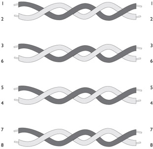
Figure 9-1: A twisted-pair cable properly terminated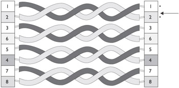
Figure 9-2: A cross-pinning condition on a TP cable. The top wire pair has too much twist removed.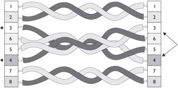
Figure 9-3: Two pairs of this TP cable have been reversed - OpenAn open circuit lacks continuity between the pins on each end of the cable, indicating that a wire has been broken or one of the pins is not properly attached (see Figure 9-4).
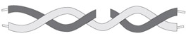
Figure 9-4: An open circuit in a TP wire pair - ShortA short occurs when two or more conductor wires in a cable are in contact or if a metal object, such as a nail or staple penetrates the cable and creates a contact between two or more conductors (see Figure 9-5).
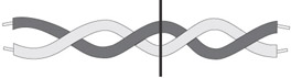
Figure 9-5: A nail or staple penetrating a wire can cause a short circuit. - Split pairIf one conductor of a wire pair is connected to the wrong pin at each end of the wire, which in effect splits the pair, the cable will not function properly. Figure 9-6 illustrates this condition.
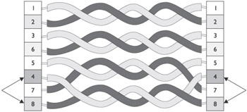
Figure 9-6: A split wire pair causes this TP cable to be terminated improperly - TerminationIf a cable termination changes the impedance of the cable, which should be 100 ohms on a TP cable and 75 ohms on a coaxial cable, the transmitted signal may be reflected by the terminator and cause data loss.
Diagnosing TP Cable
When a cable is suspected to have a fault, you must be able to locate it in order to fix it. You need to be able to identify whether or not the fault is on a certain pin or at some distance along the cable, or even as far away as the far-end connector.
The two test procedures that can be helpful in determining where a fault may exist on a cable—if one exists at all—are Wiremap and Time Domain Reflectometry (TDR).
Wire Map TestingWhen a cable fault is first suspected as the source of a problem, perhaps the most useful and informative test that can be performed on residential structured wiring, especially TP cable, is a wire map test.
Wiremap testers are often incorporated into a TDR tester. The tester shown in Figure 9-7 verifies the pin-to-pin connectivity between the ends of a cable and in doing so eliminates or finds any of the problems described in the preceding section.
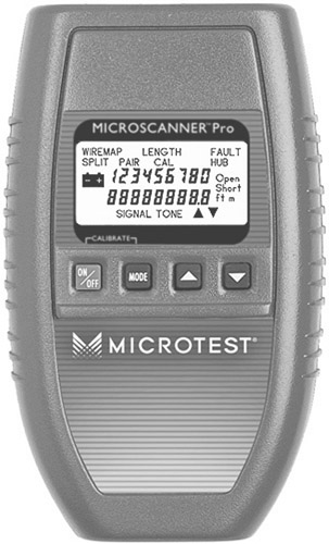
Figure 9-7: A data communication tester that performs wire map and TDR testing
Photo courtesy of Everett Communications.
TDR TestingA Time Domain Reflectometer (TDR) transmits a signal on a conductor and measures the time required for the signal, or some part of the signal, to return. If a fault exists on a conductor, the signal is reflected at the point of the fault. The amount of time required for this to take place is then converted into a distance using a formula that involves the speed of light, the velocity of propagation, and some simple arithmetic.
A TDR tester can tell you only where a problem may be, meaning at what distance from the test point, and not what type of problem may exist. Any cable that has two metal conductors can be tested using TDR, which makes it perfect for testing twisted-pair cabling (refer to Figure 9-7).
MultimeterA commonly used tool for testing cable is a multimeter, shown in Figure 9-8, which can be used for testing voltage, current, resistance, and continuity on a copper wire. The most common problem with copper wire cabling is an open-circuit. Using the resistance test (or ohm test) of a multimeter is the easiest way to test for this problem.
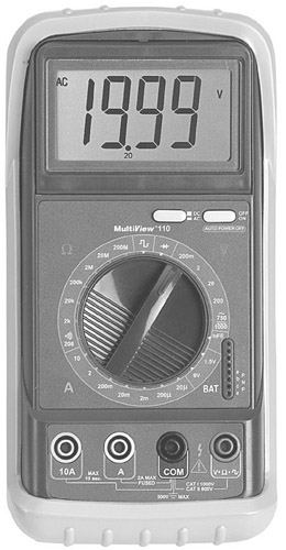
Figure 9-8: A handheld digital multimeter
Toner/Probe TestingAnother common testing procedure uses a tone generator and probe to identify one cable from a bundle or find a cable inside a wall or under a floor. This test is also referred to as “fox and hound.” The tone generator generates a specific signal on the cable and the probe converts it to an audible tone. The closer the probe is placed to the cable carrying the generated signal, the louder the audible tone is sounded. Figure 9-9 shows both a tone generator and probe.
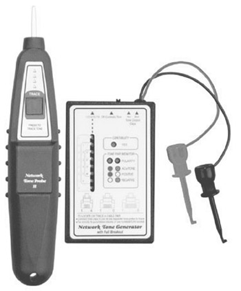
Figure 9-9: A tone generator and probe are used to locate cables and wires
Testing Coaxial Cable
Testing coaxial cabling is less complex than testing TP cable. First of all, there is only one conductor, so the tests performed by a tone generator and probe, a multimeter, and a TDR are typically sufficient for tracking down any problem.
Coaxial cable is generally more durable than TP cable, but it can develop many of the same types of cable faults. However, problems on a coaxial cable are typically caused by improper termination or damage to the cable.
Coaxial cable can exhibit many of the same cable faults as a TP cable, except, of course, those involving wire pairs specifically. However, although a coaxial cable has only one center conductor, remember that the metallic shielding on the cable also carries current and between these two conductors some faults can occur.
When troubleshooting a coaxial cable, here are some physical conditions to check for:
- The coaxial cable must match the impedance requirements of the equipment to which it is attached. Coaxial cable with a cable TV system must be 75 ohm. The coaxial cable for a data network must be 50 ohm. If 75-ohm cable is used for a data network intermittent data errors, which are very hard to track down, are likely to occur.
- Be sure the connectors and terminators attached to the cable are the correct size and match the impedance of the cable. Using the wrong connectors or terminators can cause signal faults on the cable.
- Make sure that each end of the cable is properly terminated and, although this is somewhat obvious, be sure that there are two connectors or terminators on each cable segment.
- Avoid using twist-on connectors because they can loosen easily and cause intermittent problems. Use crimp-on connectors and apply them with a good quality crimping tool made for coaxial cable. Be sure the tool and the connectors are fitted for the type of coaxial cable you are using, such as RG6. Don’t use pliers or the like to attach the connectors.
- Ensure that only one end of a coaxial cable is grounded. Grounding both can cause intermittent transmission problems.
- If you are using BNC-T connectors with a PC network, make sure the “T” is connected directly to a PC and not connected to a patch cord that connects to the PC.
Cable Tests
Cable testers designed to test coaxial cable specifically are available, but a better investment is usually a tester that is capable of testing both TP and coaxial cabling (see Figure 9-10).

Figure 9-10: Many testers include testing capabilities for both coaxial and TP cabling.
Photo courtesy of Fluke Networks.
The standard tests used for troubleshooting coaxial cable are as follows:
- AttenuationCoaxial cable has a segment length limit of 185 meters (about 607 feet) when used in a data network, which should be more than adequate for any home network. However, attenuation can be a problem for coaxial cabling that is run to exterior cameras and other devices.
- CrosstalkIf the cable has been crushed or otherwise damaged, the inner conductor and the outer conductor energies can cause crosstalk between the two conductors.
- ImpedanceThe impedance of the cable should match the requirements of the equipment to which it’s connected, and the impedance of the connectors must match that of the cable.
- TDRThe TDR testing of a coaxial cable measures the length of the cable to a reflection point, which (one hopes) is the terminator or connector on the end of the cable. If the TDR test detects a short or open circuit that causes the test signal to reflect before the termination, the point in the cable where the problem exists is returned.
Review
A suspected cabling problem must be identified and isolated before an appropriate solution can be applied. Each type of cable has its own unique potential problems and each of these problems should be eliminated through a methodical diagnostics process. A recommended approach for identifying a cabling problem involves the following steps: listen, look, inspect, and test.
A written record should be maintained for all problems reported or even suspected. Whenever a technician responds to diagnose, troubleshoot, or resolve a cabling problem, the problem, diagnostics, and the solution should be recorded in a maintenance log.
Cable problems are most likely caused by damage to the cable, improper termination or mis-wiring that may have been introduced during rough-in, trim-out, or during construction. The cable may have been nailed, stapled, cut, crimped, or crushed. Common TP cable problems include: cable impedance, crossed pinning, open circuit, short circuit, split pair, and improper termination.
Two test procedures can be helpful in determining where a fault exists on a cable: Time Domain Reflectometry (TDR) and wire map. The most commonly used tool for testing cable is a multimeter, which is used for testing voltage, current, resistance, and continuity on a copper wire.
A Time Domain Reflectometer (TDR) transmits a signal on a conductor and measures the time required for the signal, or some part of the signal, to return. If a fault exists on a conductor, the signal is reflected at the point of the fault. The amount of time required for this to take place is then converted into a distance.
When a cable fault is first suspected as the source of a problem, perhaps the most useful and informative test that can be performed on residential structured wiring, especially TP cable, is a wire map test. Wiremap testers verify the pin-to-pin connectivity between the ends of a cable. A tone generator and probe are used to identify one cable in a bundle or to find a cable inside a wall.
Testing coaxial cabling is less complex than testing TP cable. First of all, there is only one conductor, so the tests performed by a multimeter, TDR, and a tone generator and probe are typically sufficient for tracking down any problem. The standard tests used for troubleshooting coaxial cable are: attenuation, crosstalk, impedance, and TDR testing.
Questions
- Which of the following are advantages of structured wiring over conventional “daisy chained” wiring schemes?
- No splices
- Home runs
- Central maintenance and configuration point
- All of the above.
- Which of the following is not listed in this chapter as an approach for identifying a cable problem?
- Listen
- Look
- Replace suspected cable runs
- Test
- When should a record be created that documents the testing and performance of a structured wiring system?
- On the first visit to investigate a problem
- During trim-out
- After solving a problem
- Only after fixing “real” problems
- Which of the following problems is not a common issue with a structured wiring system?
- Attenuation
- Reversed pairs
- Open circuits
- Improper termination
- After completing the trim-out and finish work of a structured wiring system, the homeowner calls to complain that one of the PCs attached to the data networking system cannot be reached from other PCs in the home for file sharing. After diagnostic testing, you discover that the fault is a short about 20 feet up the TP cable connecting the PC to the patch panel. What diagnostic test was likely used to determine this information?
- Ohm (resistance) test
- Tone generator/probe test
- Wire map test
- TDR test
- The pinout of the connector on a TP cable is incorrect at one end of the cable and the transmitted signal is not being received correctly. What type of problem does this describe?
- Impedance
- Cross pinning
- Open circuit
- Short circuit
- What impedance level should a TP cable have?
- 50 ohms
- 75 ohms
- 100 ohms
- 150 ohms
- Which type of test device is able to verify the pin-to-pin connectivity between two ends of a cable?
- TDR
- Multimeter
- Tone generator/probe
- Wiremap
- Which type of cable testing device can be used to locate a single cable in a wall that is a part of a cable bundle?
- TDR
- Multimeter
- Tone generator/probe
- Wiremap
- Which of the following is not a common cable fault of a coaxial cable?
- Improper termination
- Cable damage
- Impedance of 35 ohms
- Split pairs
Answers
- D. All of these choices represent advantages of structured wiring over conventional wiring schemes.
- C. During diagnostics, this action may be wasteful and unnecessary. First gather some facts and then act.
- B. The first testing cycles performed on the cable should begin the record into which all maintenance activities are recorded.
- A. Because the cable runs tend to be less than the maximum segment length for TP cabling, attenuation is rarely an issue in residential systems.
- D. A TDR test is able to locate the position of a fault on a cable and report the distance from the test point to the fault.
- B. Because of the size of the wires and the connectors, this is a common problem for TP cabling.
- C. A TP cable that tests for less than 100 ohms may be of insufficient quality or a termination error may be causing the problem.
- D. A multimeter is also able to test for continuity, but not to identify the pins in question.
- C. The probe uses induction amplification to sense the tone generator’s signal and sound an audible tone when the cable carrying the signal is located.
- D. A coaxial cable has only a single conductor wire.
Part I - Home Technology Installation Basics
- Wire and Cable Basics
- Connector Types and Uses
- Wiring Installation Practices
- Codes, Standards, and Safety Practices
Part II - Structured Wiring
- Infrastructure Wiring Basics
- Planning a Structured Wiring Installation
- Rough-In Installation
- Trim-Out Installation
- Troubleshooting Structured Wiring
Part III - Home Computer Networks
- Computer Network Basics
- Computer Network Hardware
- Computer Network Software
- Designing and Installing a Computer Network
- Troubleshooting a Home Network
Part IV - Audio/Video Systems
- Distributed Audio System Basics
- Designing and Installing Distributed Audio Systems
- Distributed Video Basics
- Designing and Installing Distributed Video Systems
- Troubleshooting Audio Systems
- Troubleshooting Video Systems
Part V. Home Lighting Management Systems
- Home Lighting Basics
- Home Lighting Devices
- Designing a Home Lighting Control System
- Installing a Home Lighting Control System
- Troubleshooting and Maintaining Lighting Control Systems
Part VI - Telecommunications
- Home Communication System Basics
- Designing and Installing a Home Telephone System
- Troubleshooting a Home Communication System
Part VII - HVAC and Water Management
Part VIII - Security System Basics
- Security System Basics
- Designing a Home Security System
- Installing a Home Security System
- Troubleshooting and Maintaining a Home Security System
- Home Security Surveillance Systems
- Home Access Control Systems
Part IX - Home Technology Integration
- Defining Users Needs and Desires
- User Interfaces
- Home Automation Controllers
- Programming
- Integrating the Connected Home
- Other Home Technology Integration Devices
Part X - Appendices
EAN: N/A
Pages: 300
