Planning a Structured Wiring Installation
Planning a StructuredWiring Installation
In this chapter, you will learn about
- Structured wiring cable installation methods
- Planning for remodeling or new construction settings
- Planning for equipment and component placement
Structured wiring and its concepts, methods, and objectives, are the cornerstone of the home technology integration movement, as well as the certifications offered by CompTIA (HTI+), CEDIA (CEDIA Professional), and even a few manufacturers. In addition to all of this, structured wiring just makes sense for new homes. It provides the homeowner with value, convenience, and perhaps best of all, a home that has a flexible infrastructure that will be able to accommodate changes and future systems.
This chapter looks at the issues that should be considered when planning a structured wiring project and the methods that should be used to improve the design and installation phases of the project.
What Is Structured Wiring?
A good place to start a discussion on how to plan for a structured wiring installation is with an explanation of just what structured wiring is and isn’t.
Structured wiring combines all of the communications data, signal, and control cabling in a home into a single consolidated wiring system. This means that all of the cabling, including the network, telephone, video, audio, security, heating and cooling control, lighting control, and other control wiring in a home, is planned, designed, installed, and managed as a single system.
In a nonstructured wiring situation, the wiring supporting each of a home’s systems is often installed independently, using what is referred to as a daisy chain. This means that the wiring for one device is typically an extension of the wiring to another device (looped) without a central distribution and management point.
Figure 6-1 shows a slightly exaggerated illustration of a home that has been wired with a nonstructured daisy chain wiring style. As new services are added to the home, new wires are attached to the end of existing wiring and new wiring is routed using the easiest path available. Daisy chained wiring typically has been spliced to attach new runs or extend existing runs and often involves splitters and connectors embedded in walls, under floors or in attics.

Figure 6-1: An example of a home with daisy chain wiring installed
On the other hand, Figure 6-2 illustrates a simplified view of how structured wiring improves the wiring infrastructure in the same home. Each of the cable runs shown in Figure 6-2 includes all of the cabling a room requires, typically with extra wires to accommodate future needs. Two fundamental rules of a structured wiring system are that there should be no splices and each cable bundle should be installed as a home run from the room back to a central distribution center.
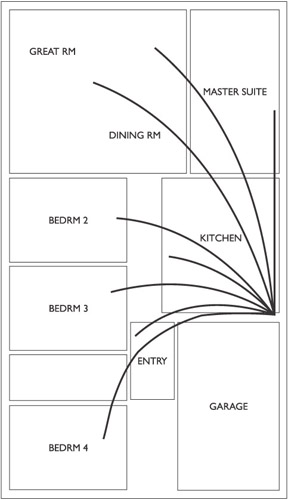
Figure 6-2: An example of a home with structured wiring installed
Table 6-1 compares just a few types of conventional wiring to a structured wiring system. However, the capabilities provided to the homeowners of a home with structured wiring are obvious.
|
System |
Conventional Wiring |
Structured Wiring |
|---|---|---|
|
Audio/Video |
Usually no pre-wire so wires are exposed Separate source devices for each room |
Wires hidden in walls Distributed audio/video Shared source devices Local control for source selection and volume |
|
Telephone |
Separate phone lines for each phone Limited to two phone lines Dial-up Internet access |
Up to four phone lines to each space Capable of handling phone system High-speed or dial-up Internet access |
|
Security (put at end) |
Grouped devices (for example, first floor) |
Individual devices known (for example, kitchen motion sensor) Interface to other home systems |
|
Data |
None installed |
In-home networking Shared information Shared devices (printer, scanner) Shared Internet access Cable modem and DSL ready |
In addition to the information in Table 6-1, the advantages of installing structured wiring in a home are
- CompatibilityStructured wiring builds a bridge between devices from different manufacturers because it provides a common and consistent platform for communications and interaction. Products that aren’t in compliance with the communications and wiring standards that also support or require structured wiring should not be designed into the home’s systems.
- ConsistencyBecause the cabling is installed as a single system, all of the wiring can be installed to avoid electrical interference and provide a more consistent audio, video, telephone, or data transmission.
- FlexibilityBecause all of a home’s cabling connects to a central distribution center, the wiring can easily be reconfigured or reapplied to other applications and the systems in the home can be changed.
- IntegrityBecause there are no wire or cable splices in the system, there are no failure points such as a location deep in a wall where a cable might pick up interference.
- Maintenance and managementEach cable in the home is individually accessible for testing and troubleshooting.
Planning for Structured Wiring
To begin planning a structured wiring installation you must first identify systems it is intended to support now and in the future. The choices for integrated and distributed systems that can be incorporated into a home’s infrastructure seem to grow daily.
System Choices
- The following are the major home automation and technology integration systems that structured wiring is installed for
- Distributed audio
- Distributed video
- Voice communications (telephone/intercom)
- Heating, ventilation, and air conditioning (HVAC) interface
- Security and surveillance
Data Networking
Ten years ago, a home may have had only one personal computer (PC) that was used for mostly personal information processing. With the exploding popularity of the Internet and the rapid developments in virtually all areas of software, it’s common for a home to now have multiple PCs used for telecommuting, personal entertainment, correspondence, and so much more.
Homes with multiple PCs commonly find themselves constrained by their dial-up or high-speed Internet connection when two or more of the users in the home wish to access the Internet at the same time. Networking a home’s PCs so that they can share a single Internet connection, as well as files and peripheral devices, is the best solution. The installation of structured wiring can link each PC in a home directly to the residential gateway of a high-speed Internet connection or a shared modem.
Distributed Audio
In the past, “whole-house audio” meant that you had really large speakers with lots of watts and turned up the volume so everyone in the house could hear it (not to mention the neighbors who were trying to sleep). Often, these speakers were freestanding and hooked only to a local system in the same room.
Structured wiring makes it possible to install speakers in every room of a house while maintaining audio equipment in one central location. The room’s occupants can choose the sound they wish to hear and control volume with controls that are set locally.
Distributed Video
What if one person wants to watch a baseball game, but someone else, in another room, wants to watch a DVD? Not a problem with a distributed video system installed on a structured wiring platform. Any video source device around the home can be selected and viewed on any TV. Local control is also possible with a structured wiring system.
Voice Communications
If properly planned, installing a home’s telephone system using a structured wiring platform can in the long run save money and nuisance for the homeowners by providing telephone outlets in every room of the house. For a home without structured wiring, the homeowner must hire a contractor or the phone company to come in and install a telephone outlet should one be needed where none exists and this could lead to yet another daisy chain wire run or cables tacked to the outside of the home or on the inside walls.
In situations where a home is serviced by multiple phone lines, the mix-and-match process of which lines are available on what phones becomes much more manageable. With a structured wiring system, a phone system that can handle multiple phones can easily be added.
Structured wiring can also easily support the installation of in-house intercom systems that can be a headache to install as a retrofit.
HVAC Control
Structured wiring and specialized HVAC systems can together provide the capability to create heating and cooling zones in a home. The benefit here is that unused areas of the home aren’t heated or cooled, thereby saving energy and money. In addition, the temperature settings for one or more rooms can be managed from a remote location or automatically based on time or occupancy.
Security and Surveillance
Structured wiring provides the means to interconnect all of a home’s sensors, detectors, locks, surveillance cameras, and lighting to a central location for control management and monitoring. Another benefit of a security system installed on structured wiring is the capability to easily link a telephone line into the security system for use with an outside monitoring service or to automatically contact the owner in the event of an alarm.
Wireless Systems
It is conceivable that a homeowner may not wish to install a structured wiring system, preferring instead to use wireless devices. This is, of course, the homeowner’s choice, but because of a lack of industry-wide standardization in the wireless industry, the task of mixing devices from several manufacturers may be formidable. In addition, wireless performance is not as consistent or dependable as hardwiring a home.
Even radio frequency (RF) and infrared (IR) technology can be integrated into a structured wiring environment. These wireless devices often need to connect to outside services, such as telephone or data networking and have their control or base units integrated into the distribution panel.
The Planning Process
Perhaps the most important part of any planning process, including the planning of structured wiring, is an understanding of exactly what it is the homeowner (customer) wishes to accomplish in the end. A homeowner views a structured wiring project in terms of the finished product and experience: the audio system (listening to music throughout the home), video system (watching TV and movies), security system (protecting the home and family), voice system (intercom to the front door), data networking system (sharing computer printer), and so on. To properly plan a structured wiring installation, you must understand the homeowner’s vision for the outcomes of the entire project. Without understanding how the systems of a home are to perform and interact, the structured wiring installation may fall short.
Locating the Central Distribution Panel
The location of the central distribution panel, also referred to as the central wiring panel, is extremely important to the success of the installation, and it can also have a direct impact on the overall cost of the project.
If the panel is located in an extreme corner of a home, forcing long cable runs to every room, the cost of cabling will definitely be higher than if the panel is centrally located. Understand that “central” is a generic term when used with wiring systems. Practically, the distribution panel should be as central as possible.
There are several candidates for the location of the distribution panel in every home, such as utility or mechanical rooms, large closets, workshop, basement, accessible attic space, or even an attached garage. The distribution panel isn’t the type of thing you want on display in a living area; not that they are ugly, but wiring is wiring and it should be located where curious minds and idle hands don’t have direct access to it. Remember that the distribution panel is the central nervous system of an automated home’s structured wiring scheme. As such, it should be somewhat secured.
The primary consideration for locating the distribution panel is that it must be kept at a distance from electrical generators and motors, fluorescent lamps, transformers, electrical wiring, and any other potential interference producing device. The space should not be either too hot or too cold and you want to be able to maintain a lower to normal humidity level. The panel is normally wall-mounted, so its location should provide ample wall space that is devoid of the aforementioned hazards. This alone should narrow down the choices for its location. Of course, if the homeowner is really into the home technology integration thing, then it is likely the home design includes a wire closet just for this purpose.
Structured wiring distribution panels can be either surface-mounted or flush-mounted. Surface-mounted panels can be installed during trim out, but a flush-mounted panel must be installed during rough-in so that it is inside the walls prior to drywall.
Developing the Planning Detail
The steps that should be used to develop the plan for a structured wiring project are
- Identify the systems to be supported and work backward.
The ultimate goal of the planning process is to identify all of the cabling that must be installed as a structured wiring system. The first step is to identify all of the systems to be installed on the structured wiring. You can then work backward from each system to determine the cabling, outlets, and locations required by each system.
- Consolidate the cabling requirements.
Each system to be integrated into the home has its own cabling requirements, most of which can be satisfied by the cabling most commonly included in structured cabling bundles: Cat 5e, coaxial cable, quad wire, and, on occasion, fiber optic cable. You should check the building and local wiring codes to ensure that each of the cable types included in a commercial structured wiring bundle is acceptable for use in your area.
Assuming a location has been chosen for the structured wiring central distribution panel, you can then map out the cable runs required for each system, determine their length, and create a consolidated list of the cabling, outlets, and faceplate components required for the job. Always provide a bit extra of everything, especially cabling, to allow for rough-in, trim-out, mistakes, and, well, you understand.
- Create a wire chart.
In the preceding step, the cable types and outlet boxes were identified, which means that you have the information required to create a wire chart that includes the information needed by the wire installers during rough-in. Table 6-2 is a sample of a wire chart that lists the first ten cable runs planned for a home. In addition to the information listed in this sample form, the length of each cable run, and perhaps status boxes that show when and who pulled, terminated, and tested each run should be added to create a complete record of the cable installation.
Table 6-2: A Sample of a Structured Wiring Planning Chart #
Type
Source
Destination
Device
Use/Comments
1
Cat 5
House feed
Distribution Panel (DP)
Phone feed
Phone feed
2
Cat 5
House feed
DP
Future
Future
3
RG-6
House feed
DP
Future
Cable feed-future
4
RG-6
Attic
DP
Future TV antenna
Loop extra cable
5
RG-6
Attic
DP
Future FM antenna
Loop extra cable
6
RG-6
Roof
DP
DSS feed
Satellite TV
7
RG-6
Roof
DP
DSS feed
Future satellite service
8
Cat 5
CC
Living room.
Phone jack
9
Cat 5
CC
Living room
Data jack
10
RG-6
CC
Living room
TV jack
- Identify and sequence the installation tasks.
The wire chart lists the cables to be pulled and outlet locations so you have the information required to begin identifying and sequencing the specific tasks to be performed. The generic steps used to install structured wiring are rough-in, trim-out, and finish. However, the approach used to accomplish these steps can vary.
- Room-by-roomWith this approach, you complete one room or zone and then move on to the next room or zone. When you use this approach, all of the cabling and rough-in devices required for a room or zone are installed to complete the rough-in for each room or zone. After the wallboards are installed, this same approach can then be used for trim-out and finish work.
- System-by-systemWith this approach, you install the components required for each system, one at a time. The downside is that pulling cable for each system separately adds more labor and cost to the job. In addition, separately pulling cabling for each system prevents the use of some prepared structured wiring bundles that are commercially available.
- Rough-in devices, then cablingPerhaps the best approach is a combination of the two preceding approaches. You first install the rough-in devices for all systems in each room and then install cabling on a room-by-room basis.
- Draw cable route mapIn addition to a sequenced list of the tasks to be performed during the installation, you should also finalize a cable route map, typically using a floor plan of the home.
- Perform a practice pre-wire walk-through.
After the wall studs are in place and the plumbers and electricians have completed their work, perform a dry run of the tasks that have been identified in the project planning.
The primary purpose of this step is to verify not only the planned cable runs, but to identify any possible problems that impact the project as planned. Use the wire chart and the marked up floor plan that shows your planned cable runs as a map and follow the cable runs in the sequence you set in the preceding step of the planning phase.
Mark the location of the cable termination on every stud, header, or floor that must be drilled. It is far better to address any problems and possible work-arounds at this time than when you are pulling cable. In fact, it’s a good idea to pre-drill all of the holes needed in the cable path before you begin actually pulling cable.
Don’t cheat on this process. Physically move through the steps and locations included in the planning. This is your ounce of prevention towards ensuring an efficient installation. If necessary, make any adjustments needed to the project plan before beginning the actual work.
Cable Planning
As mentioned earlier in this chapter, as well as the preceding chapters, the specific cabling types that are installed are determined by the systems to be installed on the structured wiring and the physical and electrical conditions through which the cable will run.
The amount of cable to be installed should be measured from the central distribution panel through the walls to the location of a room outlet box. In a home with 2,500 square feet or less, allow 75 feet for each cable run; in a home with between 3,000 and 4,000 square feet, use 100 feet per run; and in a 4,000-square foot home, use an estimate of 125 feet per run when planning the cable lengths. Table 6-3 summarizes the estimating number used in for the various home sizes. Never use exact measurements to estimate the amount of cabling required. Be generous and add at least 20 percent on the estimates and then allow extra cabling for cable loops at each outlet during rough-in.
|
Square Footage of Home |
Planning Length for Cable Runs |
|---|---|
|
2,500 or less |
75 linear feet per run |
|
3,000 to 3,999 |
100 linear feet per run |
|
4,000 to 4,999 |
125 linear feet per run |
|
5,000 or more |
150 linear feet per run |
Planning Cable Runs
For nearly all situations, the following cabling is recommended:
- To each room:
- Two runs of Category 5e cableFor use with data networking and up to four standard telephone lines or a phone system per room.
- Two runs of RG-6 coaxial cableRG-6 has the properties and characteristics required for cable or satellite television. One cable is installed for downstream (video signal coming into the room) and the second cable is for upstream (video signal out from the room).
- Where required:
- One run of 4-conductor speaker wireFor use with an audio system. Four-conductor wire allows for two stereo speakers, each using one pair of the 4-conductors.
- Various runs of twisted pair wire (quad wire or two-pair wire such as 22-2 and 22-4)For use with security system components.
- Additional runs of coaxial cable, Cat 5e cable, or other cableAs required by specific system requirements, such as for a driveway loop controller, a door telephone intercom, a connection to a sprinkler system controller, or the like.
Cabling Planning Issues
There are some basic electrical issues that need to be addressed during the planning phase for a structured wiring project as well. Even the best cable installation can have problems if the following issues aren’t addressed prior to installation:
- CurrentVerify for each system the type of current (AC versus DC) the cable is to carry.
- ESD (Electrostatic Discharge)Ensure that all cable or computer technicians wear antistatic devices when working with circuit boards and computer components. Even very small static electricity discharges can damage the delicate circuitry of electronic components.
- GroundingEnsure that the distribution panel has a connection to an earth ground. If available, a separate earth ground from that of the home’s electrical system should be used.
- PlacementVerify that each cable run is the proper distance from AC power lines and that if the structured cabling must cross an AC line, that it does so at a 90-degree angle.
- Electrical event protectionThe distribution panel should be protected from unwanted events on the source AC power line, such as brownouts and power sags and spikes. A brownout occurs when the voltage of the AC line drops below the standard range of operation and stays there for an extended time. Power sags are actually short-term brownouts and power spikes are sharp, but short, increases in the line voltage. A variety of devices can be used to protect the distribution panel and the systems it supports: surge suppressors, uninterruptible power supplies (UPS), line filters, and power regulators. Many structured wiring distribution panels come with built-in surge protection. Another less common event is a blackout, which is a complete power failure. Of the protection devices I’ve just listed, only a UPS, which acts as a battery backup, can provide power for some time after a blackout occurs.
CROSS-REFERENCE Chapters 1 and 2 cover the basics of wire choice and installation guidelines.
Another issue that you must consider when planning a structured wiring system is whether or not any cabling will run through air supply ductwork. If so, you will need to check the local, state, and national building and electrical codes to determine the required fire safety rating for the cabling that can be installed in a duct. Also, there are different standards and codes for wiring used as riser cables (between floors) and cabling that is to be installed underground. Be sure to check your local codes.
Planning for Electrical Protection
The fact that any incoming AC power required by the devices in a structured wiring project should be something you can take for granted and allow the electricians to worry about is the good news. However, the bad news is that you need to protect the structured wiring system and any devices or subsystems connected to it from that very same AC power. For reasons too numerous to list here, the normal electrical power supply system experiences random spikes, surges, and lulls almost every day. Exactly why these happen isn’t really the issue anyway. What is the issue is that protection must be designed into the system to prevent these events from damaging the devices on the structured wiring system.
Electrical Events
External AC power sources can pass on a variety of power-related problems, including the following:
- Line noiseConsists of small variations in the voltage of the power line. A small amount of line noise is normal in just about every system and all but the very low-end devices can handle it. An electrical device connected to its own circuit (an unshared power line) should have little trouble with line noise. However, for a device that shares a circuit with a refrigerator or a megaton air conditioner, line noise is not only a certainty, but it’s likely that the line noise will cause problems. For example, if a transformer is connected to an AC power source with high levels of line noise, it may eventually have its power-regulating circuits burn out, after which time the line noise would pass through to the devices connected to the transformer.
- Power surgeA power surge or spike, which is also called an over voltage event, occurs when electrical disturbances, such as distant lightning strikes or other anomalies in the electrical supply grid, create a sharp rise in the voltage level that is passed onto the power supply lines. In most situations, a spike or surge lasts only a few thousandths of a second, but, depending on the amount of the rise in the line voltage, that is plenty of time for the voltage to increase to double, triple, or spike even higher. High voltage spikes and surges, if frequent enough, can degrade the electrical circuits of a home’s electrical devices. In fact, multiple surges occurring frequently enough can eventually destroy some electrical devices, such as a computer’s power supply.
- BrownoutsCalled an under voltage event, a brownout is the opposite of a power surge (over voltage event) and occurs when there is a sudden dip in the power line voltage. In most cases, the power level drops below normal levels for a time and then returns to normal. Brownouts are extremely common during periods of heavy load on the electrical system, such as hot afternoons or cold mornings. The reduced voltage level causes many devices to run slower than normal or malfunction in other ways. Low voltage for an extended time can do just as much damage as spikes. A brownout doesn’t typically last too long, but it can.
- BlackoutsA blackout occurs when the power fails completely. The problems caused by a blackout are usually more frustrating than damaging, but the fluctuation of power surrounding a blackout can cause harm. Typically, any damage associated with a blackout occurs when the power returns suddenly, usually in the form of a huge spike.
- Lightning strikesThis is the big spike, and it can deliver a million volts or more. I don’t need to tell you what would happen if one were to hit a home directly. However, a strike even in the vicinity can result in a very high voltage spike.
Note Electrical events can cause two types of damage to an electrical device: catastrophic, which means a device is destroyed all at once by a single event, and degradation, which means a device is damaged slowly over a period of instances and begins to have intermittent problems before failing altogether.
Surge Suppression
The most common electrical system event is a power surge or spike, which is a temporary increase in the voltage supplied on the electrical lines. For the most part, any power surge to a home is passed on through the electrical distribution panel to the circuits in the home. The installation of surge suppression devices is the best and most economical way to prevent damage to any of the devices on the structured wiring system.
The least expensive and perhaps the least protective way to protect against electrical surges are power strip surge suppressors, like the one shown in Figure 6-3. Surge suppressors are generally available and the most commonly used protection device. The device shown in Figure 6-3 provides protection not only for electrical devices, but provides surge suppression to telephone and data network links as well.
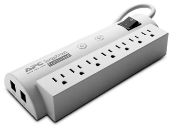
Figure 6-3: A high-end surge suppression plug strip
Photo courtesy of American Power Conversion Corporation.
The primary component of a surge suppressor is a Metal Oxide Varistor (MOV), which, in effect, takes the hit from voltage spikes. However, an MOV can be defeated by one big spike or an accumulation of small surges over time, which is why some surge suppressors have an LED to indicate that the MOV is still intact. A surge suppressor absorbs spikes and surges and smoothes out line noise, which is called line conditioning. The rule-of-thumb for selecting a surge suppressor is that you get what you pay for.
The two main features for choosing a surge suppressor are
- Clamping voltageThe voltage at which the suppressor begins to protect the circuit.
- Clamping speedThe amount of time that elapses between detection and protection.
Here are some other characteristics to consider when selecting a surge suppressor for a home system:
- Energy absorptionSurge suppressors are rated in joules, which is a measure of their capability to absorb energy. The higher the joules rating, the better the protection. Basic protection is 200 joules; 400 joules represents good protection; and 600 joules is better protection.
- Line conditioningThe line conditioning capability of a surge suppressor is measured in decibels. The more decibels of noise reduction, the better the line conditioning.
- Protection levelSurge suppressors have three levels of protection indicated as the maximum number of watts a suppressor allows to pass through. The standard ratings are (better to good) 330, 400, and 500.
Note Underwriters Laboratories (UL) standard 1449 covers the construction and performance of surge suppressors. A suppressor with a UL approval has met this standard and will provide protection to its rated capacities.
Protecting Telephone Lines
In the event of an electrical storm or lightning strike, power can surge up the telephone lines just as fast as on power lines. Surge protectors should also be installed to protect any distributed phone lines between the NID and the distribution panel. In addition, surge protect any door intercoms before they connect to the house phone system as they are located outside and susceptible to lightning hits.
Protecting Coaxial Cable Lines
Surge suppression should also be added to coaxial cable lines that connect exterior sources to interior systems, such as the lines that provide cable television, an exterior antenna, or the lines connecting a digital satellite receiver to its dish outside the home.
Three Ways An Electrical Surge Can Enter a Home
Any electrical or signal line that penetrates the shell of a home, or in other words, any line that enters a home from its exterior, is capable of carrying an electrical over voltage surge inside the home. The most common sources for surges are
- Thunder or electrical storms
- Lightning strikes on or near a home
- Extreme weather conditions, such as snow, ice, or gusty winds
A surge can be carried into a home on any or all of the following lines:
- Electrical power lines
- Telephone lines
- Video (cable, satellite, or antenna) or data service lines
To really protect a home from over voltage surges, a transient voltage suppression system (TVSS) should be installed inside the home as near to the point where an exterior line enters the home.
As a general rule, it is always a best practice to install surge protection for any of the most costly or required electronic devices, such as entertainment equipment, computers, printers, and copy machines or faxes, in a home.
The best devices for this purpose include a silicon avalanche diode (SAD) as their primary level of protection from over voltage surges that may enter and be carried on a coaxial cable into a home. SAD devices provide fast and nondegrading surge protection for coaxial data and video source lines.
Battery Backup
An uninterruptible power supply (UPS) provides a constant (uninterrupted) power stream to the electrical devices connected to it. Under normal operating conditions, most surge suppressors can handle short brownout conditions. However, when the AC voltage drops below a certain level or is disrupted completely, a UPS is designed to provide power for a certain amount of time.
All UPS units have two sets of circuits. One side is an AC circuit that provides surge suppression. The other side is a battery and a DC to AC converter. The batteries inside a UPS store a DC charge that must be converted to AC when needed to replace lost voltage.
There are two types of UPS units available, which differ in the following ways:
- StandbyThis type of UPS operates normally from its AC side. When the power drops, it switches over to its battery backup side.
- In-line UPSOperates normally from its DC or battery backup side. The AC side is used only to maintain the power stored in the batteries or in the event of a problem with the battery-powered circuits.
Note UPS units are often confused with a standby power supply (SPS), or battery backup, which supplies power only when none is available and has no power-conditioning capabilities.
The use of a UPS unit with home automation systems is optional, but in the case of electrically power telephones and security systems, having power for even a short period of time after a power failure may be a necessity in some home situations.
Review
Structured wiring combines all of the communications data, signal, and control cabling in a home into a single consolidated wiring system. This means that all of the cabling, including the network, telephone, video, audio, security, heating and cooling control, lighting control, and other control wiring in a home, is planned, designed, installed, and managed as a single system.
The advantages of installing structured wiring are compatibility, consistency, flexibility, integrity, and ease of maintenance and management.
To begin planning a structured wiring installation you must first identify systems it is intended to support now and in the future. The major home automation and technology integration systems that structured wiring is installed for include: data networking, distributed audio, distributed video, voice communications, HVAC control, and security and surveillance.
Perhaps the most important part of any planning process, including the planning of structured wiring, is an understanding of exactly what it is the homeowner (customer) wishes to accomplish in the end.
The location of the central distribution panel is extremely important to the success of the installation, as well as the overall cost of the project. The distribution panel should be as central as possible. The distribution panel must be kept at a distance from electrical generators and motors, fluorescent lamps, transformers, and electrical wiring. The space should not be either too hot or too cold and you must be able to maintain a lower to normal humidity level. Structured wiring distribution panels can be either surface-mounted or flush-mounted.
The steps that should be used to develop the plan for a structured wiring project are: identify the systems to be supported and work backwards; consolidate the cabling requirements; create wire chart; identify and sequence the installation tasks; and perform a practice pre-wire walk-through.
The amount of cable to be installed should be measured from the central distribution panel through the walls to the location of a room outlet box. For nearly all situations, each room should have two runs of Category 5e cable and two runs of RG-6 coaxial cable. Speaker wire, additional Cat 5, and coaxial cable should be installed where required.
There are some basic electrical issues that need to be addressed during the planning phase for a structured wiring project: current, ESD, grounding, placement, and electrical event protection.
External AC power sources can pass on a variety of power-related problems, including: line noise, power surge, brownouts, blackouts, and lightning strikes. Surge suppressors are generally available and the most commonly used protection device. Surge protectors should also be installed to protect any distributed phone lines between the NID and the distribution panel and any coaxial cable lines such as cable service, antenna or satellite. An uninterruptible power supply (UPS) provides a constant (uninterrupted) power stream to the electrical devices connected to it.
Questions
- Which of the following best describes structured wiring?
- All home cabling uses the same path through the walls.
- A consolidation of the communications and control cabling in a home.
- The integration of the communications and control cabling with the electrical lines in a home.
- The design and installation of communications and control cabling in a home as a single system.
- Which of the following “no-new-wire” solutions can be integrated into a structured wiring environment?
- Powerline
- HomePNA
- RF and IR
- All of the above
- Which of the following is not an advantage of a structured wiring system?
- Compatibility
- Rigidity
- Consistency
- Integrity
- Before beginning the planning for a structured wiring project, what should you first have?
- Blueprints
- Certification
- An understanding of the homeowner’s objectives
- Experience
- Which one of the following would not be an ideal location for the central distribution panel of a structured wiring system?
- A damp basement corner
- A utility closet with no electrical appliances
- A small room designed for use as a wiring closet
- A garage wall near an electrical panel
- After you’ve identified the systems to be supported by the structured wiring system, how should you proceed?
- Plan the installation of each end-user system to be installed.
- Determine the exact amount of cabling required for the job.
- Identify the systems to be installed and work backward to determine the cabling standards that must be satisfied.
- Begin pulling the general cable requirements and add any specific requirements as a later step.
- What method should be used to estimate the amount of cabling required for a structured wiring system?
- Identify the cable type and standards required by each system.
- Purchase two rolls of each type of cable to cover all possibilities.
- Measure the length of the AC lines installed.
- Determine the shortest path to each device to be installed.
- A home that has a conventional wiring scheme likely uses which type of cable installation method?
- Structured
- Daisy chain
- Ring
- Home run
- What is the minimum number of Cat 5e runs that should be installed to each room?
- 1
- 2
- 4
- Varies with types of systems in use
- Which of the following is not an electrical issue that should be considered during the planning for a structured wiring system?
- ESD
- Grounding
- Electrical events
- Number of electrical outlets in home
Answers
- D. Choice B also comes close, but structured wiring is designed and installed as a single system.
- D. All of the other choices listed (A, B, and C) are “wireless” technologies that can be integrated into a structured wiring system.
- B. To the contrary, structured wiring is a very flexible system that helps to future-proof a home.
- C. I know, this is a no-brainer, but we can all use a reminder on occasion. The other choices represent nice-to-haves, but you absolutely must know what the project is and what you plan to accomplish before you can begin.
- A. Choice D could have been another choice had I not limited you to one choice. How close the panel would be to the electrical panel would determine if the garage were a good or bad choice. Choices B and C are great locations for a distribution panel.
- C. At least in my opinion, this is the best way to proceed. This approach ensures that every system requirement is addressed in the planning.
- A. Okay, so this is another no-brainer. The cable type and standards requirements are vital to planning the installation of the cabling.
- B. Conventional wiring schemes (meaning nonstructured wiring) are typically the result of several installation phases where new wire was added to the end of an existing wire run.
- B. At least two runs of Cat 5e should be installed in each room that will be occupied in a home.
- D. Actually, the number of outlets in a home has no bearing on the design and planning of a structured wiring system, beyond their use as a guideline to the placement of structured wiring outlet boxes.
Part I - Home Technology Installation Basics
- Wire and Cable Basics
- Connector Types and Uses
- Wiring Installation Practices
- Codes, Standards, and Safety Practices
Part II - Structured Wiring
- Infrastructure Wiring Basics
- Planning a Structured Wiring Installation
- Rough-In Installation
- Trim-Out Installation
- Troubleshooting Structured Wiring
Part III - Home Computer Networks
- Computer Network Basics
- Computer Network Hardware
- Computer Network Software
- Designing and Installing a Computer Network
- Troubleshooting a Home Network
Part IV - Audio/Video Systems
- Distributed Audio System Basics
- Designing and Installing Distributed Audio Systems
- Distributed Video Basics
- Designing and Installing Distributed Video Systems
- Troubleshooting Audio Systems
- Troubleshooting Video Systems
Part V. Home Lighting Management Systems
- Home Lighting Basics
- Home Lighting Devices
- Designing a Home Lighting Control System
- Installing a Home Lighting Control System
- Troubleshooting and Maintaining Lighting Control Systems
Part VI - Telecommunications
- Home Communication System Basics
- Designing and Installing a Home Telephone System
- Troubleshooting a Home Communication System
Part VII - HVAC and Water Management
Part VIII - Security System Basics
- Security System Basics
- Designing a Home Security System
- Installing a Home Security System
- Troubleshooting and Maintaining a Home Security System
- Home Security Surveillance Systems
- Home Access Control Systems
Part IX - Home Technology Integration
- Defining Users Needs and Desires
- User Interfaces
- Home Automation Controllers
- Programming
- Integrating the Connected Home
- Other Home Technology Integration Devices
Part X - Appendices
EAN: N/A
Pages: 300
- Chapter III Two Models of Online Patronage: Why Do Consumers Shop on the Internet?
- Chapter VII Objective and Perceived Complexity and Their Impacts on Internet Communication
- Chapter X Converting Browsers to Buyers: Key Considerations in Designing Business-to-Consumer Web Sites
- Chapter XI User Satisfaction with Web Portals: An Empirical Study
- Chapter XIII Shopping Agent Web Sites: A Comparative Shopping Environment
