Frame Relay
In the past decade, Frame Relay has become a popular wide-area network (WAN) switching method. Building a WAN by creating virtual circuits inside a provider's Frame Relay network has become a much more attractive option than ordering leased lines between the locations you want to connect. Instead of paying for all those leased lines, you just pay for access to the provider's network. Of course, there is still a leased line to the provider, but it is typically fairly shortmuch shorter than a leased line between your end locations. It's easy to order the bandwidth you need for each link; furthermore, Frame Relay allows you to reserve a guaranteed minimum bandwidth (called the "committed information rate" or CIR) but lets you use as much bandwidth as is available on the network. In fact, you don't need the same speed circuits at all your sites. For example, your corporate headquarters might use a DS-3 (45-Mbps line), while your regional offices all have T1 lines.
At the physical level, a Frame Relay connection looks just like a serial interfacebecause it is. A standard leased line (typically a T1 line) connects your site to the Frame Relay provider. Although it's more complex than a simple serial interface, the complexity comes mostly from mapping the IP addresses of the nodes on your network into Data Link Connection Identifiers (DLCIs), which are the Frame Relay equivalent of addresses.
6.1.1. Important Frame Relay Terminology
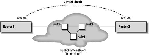
Before we look at some basic Frame Relay configurations, we need to go over a few important topics and terms. Figure 6-1 shows two routers that connect to each other through a Frame Relay network.
Figure 6-1. A virtual circuit on a Frame Relay network
Here are some terms you'll need to understand when working with Frame Relay:
Frame cloud
When connecting to a public frame network, you only know about your points of entry to the network; the interior of the network (the "cloud") is invisible to you. The network itself is often called a cloud, because you can't see what happens to your packets after they enter it.
Virtual circuit (VC)
A virtual circuit is a logical connection created by the frame provider from Point A to Point B across a frame cloud.
Data Link Connection Identifier (DLCI)
A DLCI is a value assigned by the frame provider to identify a virtual circuit. In other words, it's the Frame Relay equivalent of an address. DLCIs are unique only locally. That is, your router will have a unique DLCI for each virtual circuit it uses from one Frame Relay provider. However, as far as the Frame Relay provider is concerned, DLCIs are just numbers; the provider can reuse DLCIs throughout its network.
The router maps IP addresses to DLCIs so that it can communicate with a remote router by using the appropriate DLCI. There are two ways to map a DLCI to an IP address. First, you can allow the router to discover the DLCI by using inverse ARP, which is enabled by default. Second, you can explicitly map an IP address to a DLCI.
Local Management Interface (LMI)
The LMI is based on the type of Frame Relay switch you are connecting to. Your provider will give you this information. The LMI types are Cisco, Ansi, and q933a; Cisco is the default. Note that the routers at each end of the link may have different LMI settings, because they are connected to different types of switches.
Point-to-point
A point-to-point connection is a single virtual circuit that connects two points. In Figure 6-1, Router 1 connects to Router 2 with a frame network between them. On either side of the frame cloud is a router that knows that there is only one router at the other end. This kind of configuration is similar to connecting two routers directly over a serial line.
Multipoint
In a multipoint network, a single interface is connected to multiple virtual circuits with multiple DLCIs. Each virtual circuit is still point-to-point, but many logical point-to-point connections share the same physical interface. Subinterfaces should be used for each fully-meshed portion of the multipoint network. Remember that subinterfaces use the X.Y notation, where X is the interface and Y is the subinterface.
There are two types of multipoint networks : partially-meshed and fully-meshed. In a fully meshed network, all the routers have direct connections to each other. In contrast, in a partially meshed network, each router is connected to at least one other router, but may not have a direct connection to all the routers in the network. For example, you might have three routers, A, B, and C; Routers B and C are connected to Router A, but do not have a direct connection to each other.
Split horizon
Split horizon is a technique commonly used in routing protocols; it means that the router will not send information about a route out the same interface from which it learned the route. Split horizon is normally used to prevent routing loops. However, it can cause problems in a partially-meshed multipoint Frame Relay network. More than one router may be listening at the other end of any interface. Therefore, we don't want to suppress route announcements. For example, assume that we have three routers (i.e., three virtual circuits) connected to our multipoint interface. If a route comes to our interface from any of those points, we want to announce the route to the other two points. If split horizon is enabled, we can't send the route out our interface because that is where the route originated. However, split horizon should be enabled on a fully meshed multipoint Frame Relay network.
6.1.2. Frame Relay Configuration
Here is the most basic Frame Relay configuration . We don't give the serial interface an IP address; instead, we use the unnumbered command to tell it to "borrow" the address of the ethernet0 interface. To use this command, we must tell the router explicitly that serial2 is a point-to-point interface:
interface serial2
 no ip address
 encapsulation frame-relay ietf
 no shutdown
interface serial2.1 point-to-point
 ip unnumbered ethernet0
Okay, it will probably never be that easy. So, let's use the network pictured in Figure 6-1, where Router 1 has a DLCI of 100 and Router 2 has a DLCI of 200. Here's the configuration for Router 1:
interface serial1
 no ip address
 encapsulation frame-relay ietf
 frame-relay lmi-type ansi
 no shutdown
!
interface serial1.1 point-to-point
 description connection to baltimore
 ip unnumbered ethernet0
 ! Give the DLCI of the local end of the virtual circuit
 frame-relay interface-dlci 100
And here's the configuration for Router 2. The only thing that's different is the DLCI:
interface serial1
 no ip address
 encapsulation frame-relay ietf
 frame-relay lmi-type ansi
 no shutdown
!
interface serial1.1 point-to-point
 description connection to new-york
 ip unnumbered ethernet0
 ! Give the DLCI of the local end of the virtual circuit
 frame-relay interface-dlci 200
Some notes about this configuration:
- We were forced to break up the configuration into subinterfaces because IOS does not allow us to apply the point-to-point keyword to the main interface.
- There's no IP address for serial1's main interface, since we tie the IP address to the subinterface.
- We used ip unnumbered to establish an IP address for serial1.1. This means that the interface doesn't have its own IP address; it borrows an address from one of the router's other interfaces (in this case, ethernet0). For this to work, we had to specify that the interface is point-to-point and configure both routers appropriately.
- We explicitly defined the DLCIs on each link. We are relying on inverse ARP (enabled by default) to map the IP address of the remote end of the link to the DLCI. The next section discusses how to map addresses to DLCIs in more detail.
6.1.3. Mapping IP Addresses to DLCIs
A key part of Frame Relay configuration is mapping IP addresses to DLCIs. This mapping can take place either explicitly or implicitly. The previous example used an implicit mapping: we simply listed the DLCI for our connection and let the router use inverse ARP to map the DLCI to an IP address. With inverse ARP, the router automatically infers the IP address of the router at the other end of the DLCI. To do so, the router waits for a packet to arrive on the DLCI. The source IP address of the packet is then associated with the remote router's DLCI, allowing the router to build a map of DLCIs and IP addresses.
The primary advantage of an implicit mapping is that you don't have to reconfigure your router if the address of the remote end changes. As your network changes, the router notices the new addresses and adjusts its tables accordingly. All you have to do is list the DLCIs you know about. To clear any maps created by inverse ARP, use the command clear frame-relay-inarp. Inverse ARP is enabled by default.
For an explicit mapping, we would build the map by hand using the frame-relay map ip command. While this method removes the possibility of an error being made by inverse ARP, it is difficult to manage, especially if you have a large network with many virtual circuits.
The next two sections go into more detail about creating an explicit mapping and using implicit mapping in a multipoint configuration.
6.1.3.1. Explicitly mapping DLCIs
Here's how to create an explicit mapping between IP addresses and DLCIs. In the next section, we will see how to use the multipoint connection with implicit listing of the DLCIs.
interface serial1
 encapsulation frame-relay ietf
 frame-relay map ip 192.168.2.1 100
 ! disable inverse mapping because we no longer need it
 no frame-relay inverse-arp
With this configuration, DLCI 100 is mapped to IP address 192.168.2.1. We would add additional frame-relay map ip statements for any other addresses we care about. We don't need inverse ARP with an explicit mapping, so we disabled it.
6.1.3.2. Configuring a multipoint connection
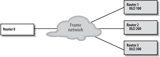
With a multipoint connection, we have one serial interface connected to a Frame Relay network. However, that interface can reach multiple destinations. For example, if we need to communicate with three destinations through the Frame Relay network, as in Figure 6-2, we can create three logical interfaces on a single physical serial interface and then treat each destination as if it has its own interface.
Figure 6-2. Multipoint configuration
There are a couple of ways to configure the router for this network. The simple, laborious way is to list every virtual circuit, giving each one a point-to-point subinterface. Here's the configuration for Router 0:
interface serial1
 encapsulation frame-relay ietf
 frame-relay lmi-type ansi
 no shutdown
!
interface serial1.1 point-to-point
 ip address 192.168.1.5 255.255.255.252
 description connection to New York
 frame-relay interface-dlci 100
!
interface serial1.2 point-to-point
 ip address 192.168.2.5 255.255.255.252
 description connection to Texas
 frame-relay interface-dlci 200
!
interface serial1.3 point-to-point
 ip address 192.168.3.5 255.255.255.252
 description connection to Pasadena
 frame-relay interface-dlci 300
Let's do it again, this time using the multipoint option so we don't have to configure each virtual circuit separately:
interface serial1
 no ip address
 encapsulation frame-relay ietf
 frame-relay lmi-type ansi
 ! disable split-horizon
 no ip split-horizon
 no shutdown
!
interface serial1.1 multipoint
 description connection to New York, Texas, and Pasadena
 ip address 192.168.1.1 255.255.255.0
 ! List all the DLCIs and let the router figure out the mapping
 frame-relay interface-dlci 100
 frame-relay interface-dlci 200
 frame-relay interface-dlci 300
Once again, we listed all the DLCIs that are available for this interface. However, we pushed them all into one multipoint subinterface. The router uses inverse ARP to figure out the IP addresses for the remote end of the connection. We could also have used the frame-relay map command to explicitly map each DLCI to an IP address, but that would be much more work in a large network.
6.1.4. Frame Relay Traffic Shaping
With traffic shaping , we control how fast packets are sent or received on our interface (this and many other topics are described in detail in Chapter 11). But the control that frame relay traffic shaping offers is more fine-grained than this. We can shape our traffic for each virtual circuit, not just by interface. In this way, we can ensure that busy virtual circuits do not hog all the bandwidth. We can also use the FECN and BECN signals to modify our traffic shaping.
Before we look at some examples of traffic shaping, let's review a few terms:
Committed Information Rate (CIR)
The rate at which our network is allowed to transfer packets over a frame relay network. This rate (in bits per second) is a guaranteed by our provider. We might be able to go faster than this rate, but it's not guaranteed.
Burst size (Bc)
The committed burst size or "sustainable" burst size. Under normal operating conditions, your service provider allows you to reach this traffic level.
Interval (Tc)
This parameter cannot be configured. The router calculates this measurement using the following formula:
Tc = Bc/CIR in seconds
This value is the interval (in seconds) that you send the Bc bits in order to maintain the average rate of the CIR in seconds.
Excess burst size (Be)
The excess burst size is well outside the CIR value. It's the burst size that you can send out on your network, but the traffic is not guaranteed for delivery. Traffic that reaches this burst rate is marked for discard eligibility within the frame-relay network. At least, this is true in theory. In practice, not all carriers mark traffic for discard eligibility (DE), making DE statistics difficult to trust.
Forward Explicit Congestion Notification (FECN)
A bit that's set within a packet to notify the receiving device that there is congestion within the frame relay network. Although, the device is receiving the packethence the "forward notification"the device can still use that information when it comes time to transmit its own packets.
Backward Explicit Congestion Notification (BECN)
A bit that's set within a packet to notify the sending device that one of its frames encountered congestion. It doesn't apply to the packet that is marked with a BECN; it's an automatic action taken after setting an FECN. The next packet that goes back to the device (hence the term "backward") is marked with BECN to notify the device that it should probably slow down its transmissions.
6.1.4.1. Enabling traffic-shaping on a frame relay link
Before we start configuring traffic-shaping on a frame relay interface, we need to use the frame-relay traffic-shaping command. We can use this command on the main interface instead of the subinterface. In this configuration, we see the standard frame relay configuration on serial0 with two frame relay virtual circuits, 100 and 200. We enable traffic-shaping on the serial0 interface.
interface serial0
 no ip address
 encapsulation frame-relay
 frame-relay traffic-shaping
!
interface serial0.100
 ip address 10.1.1.1 255.255.255.252
 frame-relay interface-dlci 100
!
interface serial0.200
 ip address 10.1.1.5 255.255.255.252
 frame-relay interface-dlci 200
Now we can enable some traffic-shaping commands. First, we'll set some CIR values with the frame-relay traffic-rate command. For DLCI 100, we want the average to be 64,000 with a peak of 128,000. DLCI 200 runs a little slower, with an average of 4,800 and a peak of 9,600.
interface serial0
 no ip address
 encapsulation frame-relay
 frame-relay traffic-shaping
!
interface serial0.100
 ip address 10.1.1.1 255.255.255.252
 frame-relay interface-dlci 100
 class fast-class
!
interface serial0.200
 ip address 10.1.1.5 255.255.255.252
 frame-relay interface-dlci 200
 class slow-class
!
map-class frame-relay fast-class
 frame-relay traffic-rate 64000 128000
!
map-class frame-relay slow-class
 frame-relay traffic-rate 4800 9600
Although we used the frame-relay traffic-rate command, which allowed us to define all the values on one line, we could have used frame-relay cir, frame-relay mincir, frame-relay be out, and frame-relay bc out commands, which accomplish the same thing. In the previous example, we had 64,000 for our average CIR rate and 128,000 for our peak rate. In this example, we'll set the max burstable size to 128,000 and our minimum cir (guaranteed rate) to 64,000. For example:
map-class frame-relay fast-class
 ! Set the CIR to the average rate we WANT to send out
 frame-relay cir 128000
 ! Set the mincir to the guaranteed rate from our ISP
 frame-relay mincir 64000
 ! Set our burst rates
 frame-relay bc 16000
 frame-relay be 16000
6.1.4.2. Adaptive shaping
Adaptive shaping allows the router to adapt its transmit rate in response to BECNs received. If any BECNs are received from by the router during the current time interval, the transmit rate is decreased by 25 percent. The rates continue to drop with each BECN until the rate reaches the guaranteed CIR rate (mincir). There can be only one rate drop per interval. Once BECNs are no longer received, the router waits for 16 time intervals to pass with no more BECNS before it starts to increase the rate again. To enable this feature, use the frame-relay adaptive -shaping becn command:
map-class frame-relay slow-class
 !
 frame-relay adaptive-shaping becn
6.1.5. Frame Relay show Commands
Table 6-1 lists the show commands that are useful for configuring and troubleshooting frame relay connections.
|
Command |
Displays |
|---|---|
|
show interface |
DLCI and LMI settings |
|
show frame-relay lmi |
LMI statistics |
|
show frame-relay pvc |
Frame relay PVC statistics |
|
show frame-relay map |
Current frame relay map information |
|
show frame-relay traffic |
Traffic statistics and information |
|
show frame-relay route |
Configured static routes for frame relay |
|
show frame-relay svc |
Current SVCs |
Getting Started
- Getting Started
- IOS User Modes
- Command-Line Completion
- Get to Know the Question Mark
- Command-Line Editing Keys
- Pausing Output
- show Commands
IOS Images and Configuration Files
- IOS Images and Configuration Files
- IOS Image Filenames
- The New Cisco IOS Packaging Model
- Loading Image Files Through the Network
- Using the IOS Filesystem for Images
- The Routers Configuration
- Loading Configuration Files
Basic Router Configuration
- Basic Router Configuration
- Setting the Router Name
- Setting the System Prompt
- Configuration Comments
- The Enable Password
- Mapping Hostnames to IP Addresses
- Setting the Routers Time
- Enabling SNMP
- Cisco Discovery Protocol
- System Banners
Line Commands
- Line Commands
- The line Command
- The Console Port
- Virtual Terminals (VTYs)
- Asynchronous Ports (TTYs)
- The Auxiliary (AUX) Port
- show line
- Reverse Telnet
- Common Configuration Items
Interface Commands
- Interface Commands
- Naming and Numbering Interfaces
- Basic Interface Configuration Commands
- The Loopback Interface
- The Null Interface
- Ethernet, Fast Ethernet, and Gigabit Ethernet Interfaces
- Token Ring Interfaces
- ISDN Interfaces
- Serial Interfaces
- Asynchronous Interfaces
- Interface show Commands
Networking Technologies
Access Lists
IP Routing Topics
- IP Routing Topics
- Autonomous System (AS) Numbers
- Interior and Exterior Gateway Protocols
- Distance-Vector and Link-State Routing Protocols
- Static Routes
- Split Horizon
- Passive Interfaces
- Fast Switching and Process Switching
Interior Routing Protocols
Border Gateway Protocol
- Border Gateway Protocol
- Introduction to BGP
- A Simple BGP Configuration
- Route Filtering
- An Advanced BGP Configuration
- Neighbor Authentication
- Peer Groups
- Route Reflectors
- BGP Confederacies
- BGP TTL Security
Quality of Service
- Quality of Service
- Marking
- Older Queuing Methods
- Modern IOS QoS Tools
- Congestion Avoidance
- Traffic Policing
- Traffic Shaping
- AutoQoS
- QoS Device Manager
Dial-on-Demand Routing
- Dial-on-Demand Routing
- Configuring a Simple DDR Connection
- Sample Legacy DDR Configurations
- Dialer Interfaces (Dialer Profiles)
- Multilink PPP
- Snapshot DDR
Specialized Networking Topics
- Specialized Networking Topics
- Bridging
- Hot Standby Routing Protocol (HSRP)
- Network Address Translation (NAT)
- Tunnels
- Encrypted Tunnels
- Multicast Routing
- Multiprotocol Label Switching (MPLS)
Switches and VLANs
- Switches and VLANs
- Switch Terminology
- IOS on Switches
- Basic Switch Configuration
- Trunking
- Switch Monitor Port for IDS or Sniffers
- Troubleshooting Switches
Router Security
- Router Security
- Securing Enable Mode Access
- Routine Security Measures
- Restricting Access to Your Router
Troubleshooting and Logging
Quick Reference
Appendix A Network Basics
Index
EAN: 2147483647
Pages: 1031
