Fast Switching and Process Switching
Whether you use fast switching or process switching can affect the way your routes behave. In one project with which I was involved, the administrators wanted to balance traffic across two T1 lines using EIGRP to perform load balancing . They observed that a daily file transfer always used a single line, which wasn't what they wanted. The problem was that EIGRP's load balancing is session-based, not packet-based. Therefore, once the file transfer started, it was able to use only one of the lines. The solution was to configure the router for process switching rather than fast switching, because process switching is able to load balance on a per-packet basis.
Before looking at this example further, let's look more closely at the difference between fast switching and process switching and the effect each has on routing.
8.7.1. Fast Switching
When the first packet of a session is going out an interface, a route is selected and placed in a route cache. This route cache entry is used for all packets belonging to this specific destination, which means that all packets belonging to the session take the same route. An entry remains in the route cache until the route cache is flushed, the route changes, or the cache overflows. (When a cache overflows, the entry that was least recently used is removed.)
A session is a communication on a port to a specific host. For example, if Host A is FTPing to Host B, each file is transferred in a single session. Successive file transfers require new sessionsi.e., different connections between the client and the server, using different ports. Looking back at the load-balancing problem we discussed at the beginning of this section, we can see that EIGRP would have been able to perform load balancing across the T1 lines if there were multiple file transfer sessions. Since there was only one file transfer, there was only one session, and there was nothing EIGRP could do. There was no way to put the second line to use.
A route cache eliminates the need for the router to select a new route for each packet of a session. Since selecting a route takes time, the route cache saves processing time and lessens the packet's time inside the router. The first packet of the session determines the route; this route is used for every packet for this destination for as long as the route remains in the route cache.
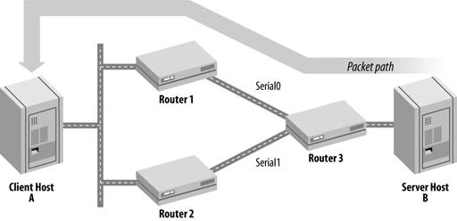
In Figure 8-4, Router 3 has chosen to send the first packet of a file transfer via Router 1; therefore, this route was added to the route cache. The server, Host B, produces a great deal of traffic for this session, all of which goes across the serial0 interface (i.e., to Router 1). Load sharing when using fast switching is session-oriented, not packet-oriented, so Router 3 will use serial0 for the entire file transfer even if there is no traffic on serial1.
Figure 8-4. Load sharing with fast switching
8.7.2. Process Switching
Process switching is the opposite of fast switching. Every packet that comes into the router is handled independently and can take a different path to its destination. Process switching therefore allows load sharing across links that might otherwise not be utilized. Load sharing is not the same as load balancing; load balancing requires more thought on the router's part than simply picking a route for every packet.
Process switching presents two problems: the CPU has to do more work because each packet has to be processed, and sending packets via different routes might cause the packets to arrive at the destination out of sequence. If the packets arrive out of sequence, the destination host needs to do more work to place the packets back together in the correct sequence, which burns up more CPU time and possibly degrades performance.
To enable process switching on an interface, use the no ip route-cache command, which disables the route cache on an interface. A new route must be selected for every packet of a session.
For example, let's revisit Figure 8-4. If the main purpose of the remote site were to transfer data every few hours across our T1s, and nothing else, we might want to optimize the router's configuration so that it uses both T1 lines for these file transfer sessions. To do so, we would add the following to Router 3's configuration:
! disable route cache on both interfaces
interface serial0
 no ip route-cache
!
interface serial1
 no ip route-cache
Now both lines are used to transmit that session's data. Since there is no route cache, load sharing will be handled on a per-packet basis, spreading the load of the file transfer across the two T1s. This feature works well in this example because of the nature of our network and the requirements of our application. In many other environments, disabling the route cache would be a bad idea. For example, a real-time video feed would require a lot of bandwidth and could benefit from load balancingbut the application probably couldn't tolerate packets arriving out of sequence. In other situations, the additional overhead of process switching might degrade the router's performance so much that the actual throughput wouldn't be satisfactory.
8.7.3. Useful show Commands
The most useful show command for IP routing is show ip route, which we used earlier when talking about redistribution. Here is an example of its output:
Router1#show ip route
Codes: C - connected, S - static, I - IGRP, R - RIP, M - mobile, B - BGP
 D - EIGRP, EX - EIGRP external, O - OSPF, IA - OSPF inter area
 N1 - OSPF NSSA external type 1, N2 - OSPF NSSA external type 2
 E1 - OSPF external type 1, E2 - OSPF external type 2, E - EGP
 i - IS-IS, L1 - IS-IS level-1, L2 - IS-IS level-2, * - candidate default
 U - per-user static route, o - ODR

Gateway of last resort is 172.30.1.2 to network 0.0.0.0

 172.30.0.0/24 is subnetted, 1 subnets
C 172.30.1.0 is directly connected, Ethernet0
D 192.168.4.0/24 [90/2195456] via 192.168.3.2, 00:00:47, Serial0
R 192.168.1.0/24 [120/1] via 192.168.2.2, 00:00:20, Serial1
C 192.168.2.0/24 is directly connected, Serial1
C 192.168.3.0/24 is directly connected, Serial0
S* 0.0.0.0/0 [1/0] via 172.30.1.2
In this example, we have three connected routes, which are listed with a C. We have one EIGRP route for network 192.168.4.0/24, which is listed with a D. And finally, the R tells us that we have one RIP route for the network 192.168.1.0/24.
We can take this one step further by adding a network to the end of the command to get specific information for that route. For example:
Router1#show ip route 172.30.1.0
Routing entry for 172.30.1.0/24
 Known via "connected", distance 0, metric 0 (connected)
 Routing Descriptor Blocks:
 * directly connected, via Ethernet0
 Route metric is 0, traffic share count is 1

Router1#show ip route 192.168.1.0
Routing entry for 192.168.1.0/24
 Known via "rip", distance 120, metric 1
 Redistributing via eigrp 100, rip
 Advertised by eigrp 100
 Last update from 192.168.2.2 on Serial1, 00:00:03 ago
 Routing Descriptor Blocks:
 * 192.168.2.2, from 192.168.2.2, 00:00:03 ago, via Serial1
 Route metric is 1, traffic share count is 1
The last two commands ask for specific route information for the 172.30.1.0 and 192.168.1.0 networks. Given the output, we can see how the router learned the route, which is "connected" in the first example and "rip" the second example. We can see that the 192.168.1.0 network is redistributed into EIGRP, which also advertises it. Finally, we can see when the last routing update occurred.
8.7.3.1. show ip route summary
A useful option to show ip route is summary. Our router gives us the following output:
Router1#show ip route summary
Route Source Networks Subnets Overhead Memory (bytes)
connected 2 1 156 552
static 1 0 52 184
eigrp 100 1 0 52 184
rip 1 0 52 184
internal 1 138
Total 6 1 312 1242
This output shows us all the different route sources (connected, internal, static, eigrp, and rip) that are currently configured and running on our router. For each route source, this command shows the total number of networks it has reported and the total number of subnets. The Overhead and Memory columns aren't particularly meaningful. Taken together, they represent the total amount of memory required by these routes. It's not clear what you could do with this information, except possibly to determine that you need to buy memory expansion if your routing table includes a particularly large number of routes.
8.7.3.2. clear ip route
The clear ip route command allows you to remove entries from the router's routing table. With an IP address as an argument, it clears routes for that particular address. With * as an argument, it clears the entire routing table:
Router#clear ip route *
8.7.3.3. show ip protocols
The command show ip protocols gives us a detailed account of each routing protocol that is currently running on the router. Most of the output from this command should look familiar if you know the routing protocols you're using. Here is the output from a router running EIGRP and RIP:
Router1#show ip protocols
Routing Protocol is "eigrp 100"
 Outgoing update filter list for all interfaces is
 Incoming update filter list for all interfaces is
 Default networks flagged in outgoing updates
 Default networks accepted from incoming updates
 EIGRP metric weight K1=1, K2=0, K3=1, K4=0, K5=0
 EIGRP maximum hopcount 100
 EIGRP maximum metric variance 1
 Default redistribution metric is 1000 250 255 1 1500
 Redistributing: static, eigrp 100, rip
 Automatic network summarization is in effect
 Automatic address summarization:
 192.168.4.0/24 for Serial0
 Routing for Networks:
 192.168.3.0
 192.168.4.0
 Passive Interface(s):
 Serial1
 Routing Information Sources:
 Gateway Distance Last Update
 192.168.3.2 90 00:21:33
 Distance: internal 90 external 170

Routing Protocol is "rip"
 Sending updates every 30 seconds, next due in 14 seconds
 Invalid after 180 seconds, hold down 180, flushed after 240
 Outgoing update filter list for all interfaces is
 Incoming update filter list for all interfaces is
 Default redistribution metric is 10
 Redistributing: static, eigrp 100, rip
 Default version control: send version 1, receive any version
 Interface Send Recv Key-chain
 Serial1 1 1 2
 Routing for Networks:
 192.168.1.0
 192.168.2.0
 Passive Interface(s):
 Serial0
 Routing Information Sources:
 Gateway Distance Last Update
 192.168.2.2 120 00:00:06
 Distance: (default is 120)
Getting Started
- Getting Started
- IOS User Modes
- Command-Line Completion
- Get to Know the Question Mark
- Command-Line Editing Keys
- Pausing Output
- show Commands
IOS Images and Configuration Files
- IOS Images and Configuration Files
- IOS Image Filenames
- The New Cisco IOS Packaging Model
- Loading Image Files Through the Network
- Using the IOS Filesystem for Images
- The Routers Configuration
- Loading Configuration Files
Basic Router Configuration
- Basic Router Configuration
- Setting the Router Name
- Setting the System Prompt
- Configuration Comments
- The Enable Password
- Mapping Hostnames to IP Addresses
- Setting the Routers Time
- Enabling SNMP
- Cisco Discovery Protocol
- System Banners
Line Commands
- Line Commands
- The line Command
- The Console Port
- Virtual Terminals (VTYs)
- Asynchronous Ports (TTYs)
- The Auxiliary (AUX) Port
- show line
- Reverse Telnet
- Common Configuration Items
Interface Commands
- Interface Commands
- Naming and Numbering Interfaces
- Basic Interface Configuration Commands
- The Loopback Interface
- The Null Interface
- Ethernet, Fast Ethernet, and Gigabit Ethernet Interfaces
- Token Ring Interfaces
- ISDN Interfaces
- Serial Interfaces
- Asynchronous Interfaces
- Interface show Commands
Networking Technologies
Access Lists
IP Routing Topics
- IP Routing Topics
- Autonomous System (AS) Numbers
- Interior and Exterior Gateway Protocols
- Distance-Vector and Link-State Routing Protocols
- Static Routes
- Split Horizon
- Passive Interfaces
- Fast Switching and Process Switching
Interior Routing Protocols
Border Gateway Protocol
- Border Gateway Protocol
- Introduction to BGP
- A Simple BGP Configuration
- Route Filtering
- An Advanced BGP Configuration
- Neighbor Authentication
- Peer Groups
- Route Reflectors
- BGP Confederacies
- BGP TTL Security
Quality of Service
- Quality of Service
- Marking
- Older Queuing Methods
- Modern IOS QoS Tools
- Congestion Avoidance
- Traffic Policing
- Traffic Shaping
- AutoQoS
- QoS Device Manager
Dial-on-Demand Routing
- Dial-on-Demand Routing
- Configuring a Simple DDR Connection
- Sample Legacy DDR Configurations
- Dialer Interfaces (Dialer Profiles)
- Multilink PPP
- Snapshot DDR
Specialized Networking Topics
- Specialized Networking Topics
- Bridging
- Hot Standby Routing Protocol (HSRP)
- Network Address Translation (NAT)
- Tunnels
- Encrypted Tunnels
- Multicast Routing
- Multiprotocol Label Switching (MPLS)
Switches and VLANs
- Switches and VLANs
- Switch Terminology
- IOS on Switches
- Basic Switch Configuration
- Trunking
- Switch Monitor Port for IDS or Sniffers
- Troubleshooting Switches
Router Security
- Router Security
- Securing Enable Mode Access
- Routine Security Measures
- Restricting Access to Your Router
Troubleshooting and Logging
Quick Reference
Appendix A Network Basics
Index
EAN: 2147483647
Pages: 1031
