Trunking
Trunking allows us to connect two devices so that they can share each other's VLANs. For example, suppose you have more than one switch on your network, and you want to configure each switch so that it has ports in VLANs 1, 2, and 3. One (unrecommended) way you could accomplish this is to run a cable for each VLAN to each switch. In this way, each interface would have a port in all the VLANs. Not only is this a waste of ports and cables, but it's terribly confusing. A much better method is to use trunking between the switches, which allows the devices to share their VLAN information easily.
Consider our previous example, with four VLANs configured on our switch. Like we just said, we could use a separate interface on the router for each VLAN. However, trunking makes this much cleaner. To better understand this concept, look at Figure 14-5.
Figure 14-5. The benefits of trunking
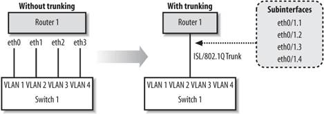
Figure 14-5 shows two options for connecting our VLANs to the router. On the left side, which is labeled "without trunking," you can see that we have used an extra interface and cable on the router to connect to each of the VLANs. What a mess. The much cleaner side, which is labeled "with trunking," shows that we can use subinterfaces on the already used FastEthernet 0/1 interface and enable a trunk to the switch. Each subinterface on the router is given a VLAN id. The router tags outgoing packets with the appropriate VLAN id before sending them out the trunk. When the switch receives the packets on the trunk port, it can identify the VLAN tag and easily forward to the correct VLAN.
There are two trunking protocols that we can use:
ISL
Inter-Switch Link is a Cisco proprietary protocol, which means it only works on Cisco devices. ISL works on Ethernet, FDDI and Token Ring networks.
802.1Q
This protocol is an industry standard that works well in mixed environments.
|

By default, all ports on a switch are access ports. In order to use a port as a trunk, you must configure it with the switchport mode trunk command. We can also set the encapsulation type with the switchport trunk encapsulation command, which is set to ISL by default:
 ! This is our router connection from before
 interface FastEthernet0/3
 description Connection to router 1
 switchport mode trunk
 ! Set the trunking to 802.1q instead of ISL
 switchport trunk encapsulation dot1q
 !
14.4.1. Restricting VLANs on a Trunk
By default, VLANs 1-1005 for ISL and 1-4095 for 802.1q are allowed to pass over a trunk. If you want to restrict which VLANs traverse the trunk port, you can use the following commands to add and remove VLANs from the allowed list:
 switchport trunk allowed VLAN remove
 switchport trunk allowed VLAN add
In a sense, the allowed list behaves like an access-list. We can verify the allowed VLAN list with the command show interface switchport allowed-VLAN. Here we can see that all VLANs are automatically allowed:
 switch1#show interface fa0/8 switchport allowed-VLAN
 "ALL"
If we had VLANs 2-200 but we only wanted allow VLANs 150-155 through the trunk, we could set it up like this:
 interface fastethernet0/8
 switchport mode trunk
 switchport trunk allowed VLAN remove 2-200
 switchport trunk allowed VLAN add 150-155
These commands first remove all our defined VLANs from the list. We add the VLANs we want to permit. We can now verify that this is the truly the case with the show command:
 switch1#show interface fa0/8 switchport allowed-VLAN
 "1,150-155,201-1005"
|

14.4.2. Finishing Our Previous Network
In the previous section, we configured our switch for the multiple VLANs shown in Figure 14-4. Now that we know about trunking, we can finish our example by enabling trunking on the router , which allows the router to have a subinterface in each of the switch's VLANs. This configuration is often referred to a "router on a stick."
Here is Router 1's configuration:
 hostname Router1
 !
 interface FastEthernet0/0
 no ip address
 !
 interface FastEthernet0/0.1
 description VLAN1 - management VLAN
 encapsulation isl 1
 ip address 192.168.1.254 255.255.255.0
 no ip redirects
 !
 interface FastEthernet0/0.2
 description HR VLAN 2
 encapsulation isl 2
 ip address 192.168.2.254 255.255.255.0
 no ip redirects
 !
 interface FastEthernet0/0.3
 description Development VLAN 3
 encapsulation isl 3
 ip address 192.168.3.254 255.255.255.0
 no ip redirects
 !
 interface FastEthernet0/0.4
 description Sales VLAN 4
 encapsulation isl 4
 ip address 192.168.4.254 255.255.255.0
 no ip redirects
Here is Switch 1's configuration. The only thing that has changed in the enabling of the trunk on FastEthernet0/3 interface, highlighted in bold. The rest of the configuration is shown for completeness.
 hostname switch1
 !
 interface VLAN1
 ip address 192.168.1.1 255.255.255.0
 no ip route-cache
 !
 interface FastEthernet0/1
 description HR router (VLAN 2)
 switchport access VLAN 2
 !
 interface FastEthernet0/2
 description Development router (VLAN 3)
 switchport access VLAN 3
 !
 interface FastEthernet0/3
 description ISL trunk back to Router1
 switchport mode trunk
 !
 interface FastEthernet0/4
 description Sales1 (VLAN 4)
 switchport access VLAN 4
 !
 interface FastEthernet0/5
 description Sales2 (VLAN 4)
 switchport access VLAN 4
 !
 interface FastEthernet0/6
 description Sales3 (VLAN 4)
 switchport access VLAN 4
To verify our configuration, we can ping the HR and Development routers from Router 1:
 Router1#ping 192.168.2.1

 Type escape sequence to abort.
 Sending 5, 100-byte ICMP Echos to 192.168.2.1, timeout is 2 seconds:
 !!!!!
 Success rate is 100 percent (5/5), round-trip min/avg/max = 4/4/4 ms
 Router1#ping 192.168.3.1

 Type escape sequence to abort.
 Sending 5, 100-byte ICMP Echos to 192.168.3.1, timeout is 2 seconds:
 !!!!!
 Success rate is 100 percent (5/5), round-trip min/avg/max = 4/4/4 ms
On the switch, we can verify that the port to Router 1 is indeed trunking:
 switch1#show interface fastethernet0/3 switchport
 Name: Fa0/3
 Switchport: Enabled
 Administrative mode: trunk
 Operational Mode: trunk
 Administrative Trunking Encapsulation: isl
 Operational Trunking Encapsulation: isl
 Negotiation of Trunking: Disabled
 Access Mode VLAN: 0 ((Inactive))
 Trunking Native Mode VLAN: 1 (default)
 Trunking VLANs Enabled: ALL
 Trunking VLANs Active: 1-4
 Pruning VLANs Enabled: NONE
14.4.3. Added Port Security
One method to secure a port is to limit the number of MAC addresses that can be detected. This feature keeps users from plugging in extra devices (with the use of a hub or switch).
To enable this feature on a 2900 or 3500 series switch, use the port security and port security max-mac-count commands. In the following example, we restrict the port to only 1 MAC address:
 interface FastEthernet 0/2
 port security
 port security max-mac-count 1
We can verify our settings with the following command:
 switch1#show port security fa0/2
 Secure Port Secure Addr Secure Addr Security Security Action
 Cnt (Current) Cnt (Max) Reject Cnt
 --------------- ------------- ----------- ---------- --------------------
 FastEthernet0/2 1 1 0 Send Trap
To take this example a little further, we could have the switch automatically send us an SNMP trap (assuming we have SNMP set up to forward to our network management station). Or, we could have the switch just shut down the port:
 interface FastEthernet 0/2
 port security
 port security max-mac-count 1
 port security action shutdown
 port security action trap
On enable port security on a 2950 or 3500 switch, the commands are a bit different:
 interface FastEthernet 0/2
 ! enable port security
 switchport port-security
 ! set the number of mac addresses
 switchport port-security maximum 1
 ! set the action to shutdown (other options are protect and restrict)
 switchport port-security violation shutdown
14.4.4. VLAN Trunking Protocol
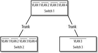
VLAN Trunking Protocol (VTP ) allows switches to communicate about VLANs across trunk ports (see Figure 14-6). VTP makes administration of multiple switches much easier. Once you configure a switch for a VTP domain and set its mode (to either client or server), the switches automatically begin sharing VLAN information from the server.
Figure 14-6. Trunks between switches with VTP management
14.4.5. VTP Modes
Switches configured with VTP have three modes : server, client, and transparent. All switches default to server mode when they are first configured for VTP. A VTP server switch can add, remove, and modify VLANs in the VLAN database. Once a change is made on a VTP server, the change is sent to all other VTP switches inside the VTP domain.
A VTP client switch pretty much just does what it's told by the VTP server switch, as long as the server is in the same VTP domain. A client cannot add, remove, or modify VLANs in the VLAN database .
In transparent mode, the switch acts as a go-between. The switch passes along VTP updates received by server switches, but the switch does not process them. A transparent switch is allowed to add, modify, and delete VLANs, but these changes remain local to the switch and are not sent out to other members of the VTP domain.
14.4.6. VLAN Database
To access the VLAN database and to configure VTP, use the VLAN database global command, which places you in VLAN configuration mode. In other words, this command is issued at the global command level, not in configuration mode, as this example shows:
 switch1#VLAN database
 switch1(VLAN)#?
 VLAN database editing buffer manipulation commands:
 abort Exit mode without applying the changes
 apply Apply current changes and bump revision number
 exit Apply changes, bump revision number, and exit mode
 no Negate a command or set its defaults
 reset Abandon current changes and reread current database
 show Show database information
 VLAN Add, delete, or modify values assoicated with a single VLAN
 vtp Perform VTP adminsitrative functions.

 switch1(VLAN)#
 switch1(VLAN)#exit
 APPLY completed.
 Exiting....
 switch1#
Notice two important things in this example. First, when we exited VLAN configuration mode, our changes were immediately applied. Second, we entered that command from global command (enable) mode, not configuration mode.
Why from global command level? In short, I don't understand Cisco's rationale for this choice. Maybe it's the same reason that VLAN database configuration commands are not kept with the rest of the router configuration. It doesn't make a lot of sense; you just have to know that's where it is.
As I said, VLAN database configurations are not stored with the regular configuration commands, which are stored in the startup configuration. On a 2900 series router, you can see a VLAN.dat file in the output of a dir command on the flash contents:
 switch1#dir flash:
 Directory of flash:

 2 -rwx 4388 Mar 01 2004 00:31:53 VLAN.dat
 8 -rwx 656 Mar 01 2004 00:29:08 config.text
You also see the config.text file, which is the switch's startup configuration. VLAN.dat is the file in which our VLAN configurations are actually stored.
While this state of affairs is a bit confusing, it is changing. On newer devices and newer versions of IOS, Cisco has begun to move VTP settings into the regular configuration mode. For example, on the newer 3550 switches, you get this message when you type in the vlan database command:
 % Warning: It is recommended to configure VLAN from config mode, as VLAN
 database mode is being deprecated.
14.4.7. Configuring VTP
The following are the most commonly used VTP configuration commands. All of these are demonstrated in the configuration example later in this section.
14.4.7.1. Setting the VTP mode
Every device starts out thinking it's a VTP server. It's up to you to tell it whether it's client, server, or transparent with the vtp server, vtp client, or vtp transparent commands.
14.4.7.2. Setting the VTP domain
All VTP devices operate only within their domain. For clients and servers to talk to each other, you need to configure the VTP domain with the vtp domain command.
14.4.7.3. Setting the VTP password
Setting the VTP password is optional. However, it provides a bit of security so that someone on your network can't hook up a Cisco switch and start creating havoc with your VTP databases. The command to use is vtp password.
14.4.7.4. Creating a VLAN
You can create a VLAN by simply using the VLAN id name text command. id is the VLAN number and text is the name you wish to give to the VLAN.
14.4.7.5. Configuration example
In our network in Figure 14-4, we had only one switch. However, let's say we wanted to hook up another switch to our network called Switch 2. Switch 2 will have VLANs 3 and 4 on it. We'll connect these switches together using port 0/8 on both switches. Then we'll configure those two ports as trunks.
Set port 0/8 to trunking on both switches:
 int fastethernet 0/8
 switchport mode trunk
 no shutdown
And on Switch 2, we'll configure the VLAN 1 interface:
 switch2(config)#interface VLAN1
 switch2(config-if)#ip address 192.168.1.2 255.255.255.0
 switch2(config-if)#no shutdown
When we first connect the switches, they both think that they are VTP servers. On Switch 1, we'll set it as server (which it already is) and configure the VTP domain.
 switch1#VLAN database
 switch1(VLAN)#vtp server
 Device mode already VTP SERVER.
 switch1(VLAN)#vtp domain xyzcorp
 Changing VTP domain name from NULL to xyzcorp
 switch1(VLAN)#vtp password vtppass
 Setting device VLAN database password to vtppass.
 switch1(VLAN)#exit
 APPLY completed.
 Exiting....
Now, configure and name the VLANs on the VTP Server, which is Switch 1:
 switch1#VLAN database
 switch1(VLAN)#VLAN 2 name HR
 VLAN 2 modified:
 Name: HR
 switch1(VLAN)#VLAN 3 name Development
 VLAN 3 modified:
 Name: Development
 switch1(VLAN)#VLAN 4 name Sales
 VLAN 4 modified:
 Name: Sales
 switch1(VLAN)#exit
 APPLY completed.
 Exiting....
After configuring the VLANs in the database, the output of show VLAN brief now displays the names we just assigned:
 switch1#show VLAN brief
 VLAN Name Status Ports
 ---- ------------------------------- --------- ----------------------------
 1 default active Fa0/7, Fa0/9, Fa0/10, Fa0/11,
 Fa0/12
 2 HR active Fa0/1
 3 Development active Fa0/2
 4 Sales active Fa0/4, Fa0/5, Fa0/6
Next, we'll configure Switch 2 as a VTP client using pretty much the same commands as we used for Switch 1. The only major difference is that this switch is a client.
 switch2#VLAN database
 switch2(VLAN)#vtp client
 Setting device to VTP CLIENT mode.
 switch2(VLAN)#vtp domain xyzcorp
 Changing VTP domain name from NULL to xyzcorp
 switch2(VLAN)#vtp password vtppass
 Setting device VLAN database password to vtppass.
 switch2(VLAN)#exit
 In CLIENT state, no apply attempted.
 Exiting....
Now, when we run show VLAN brief on Switch 2, we find that the VLAN names have propagated:
 Switch2#show VLAN brief
 VLAN Name Status Ports
 ---- -------------------------------- --------- ----------------------------
 1 default active Fa0/1, Fa0/2, Fa0/3, Fa0/4,
 Fa0/5, Fa0/6, Fa0/7, Fa0/9,
 Fa0/10, Fa0/11, Fa0/12
 2 HR active
 3 Development active
 4 Sales active
VTP works only over trunks. Therefore, if you see the VLANs come across to the second switch, you know that you must have a valid trunk. The command is the best test of our trunking configuration. Also, as you can see, we haven't configured any ports for the VLANs yet, so everything is still in VLAN 1.
Finally, a good VTP show command:
 switch2#show vtp counters
 VTP statistics:
 Summary advertisements received : 3
 Subset advertisements received : 2
 Reuqest advertisements received : 0
 Summary advertisements transmitted : 4
 Subset advertisements transmitted : 2
 Request advertisements transmitted : 2
 Number of config revision errors : 0
 Number of config digest errors : 0
 Number of V1 summary errors : 0

 VTP pruning statistics:
 Trunk Join Transmitted Join Received Summary advts received from
 non-pruning-capable device
 -------------- ---------------- ---------------- ---------------------------
 Fa0/8 0 0 0
14.4.8. Backing Up the VLAN Database
Earlier, we described how the VLAN database is stored separately from the device's starting configuration in a file called VLAN.dat. Even though this will probably change in the future, you can use it to your advantage now. If you want to, you can back up your VLAN database before you make any changes. If you want to revert to the previous configuration, use the following commands.
To back up the VLAN database:
 switch2#copy flash:VLAN.dat flash:VLAN.bak
 Source filename [VLAN.dat]?
 Destination filename [VLAN.bak]?
 4388 bytes copied in 0.131 secs
To recover a backed up version:
 switch2#copy flash:VLAN.bak flash:VLAN.dat
 Source filename [VLAN.bak]?
 Destination filename [VLAN.dat]?
 4388 bytes copied in 0.131 secs
 switch2#reload
Getting Started
- Getting Started
- IOS User Modes
- Command-Line Completion
- Get to Know the Question Mark
- Command-Line Editing Keys
- Pausing Output
- show Commands
IOS Images and Configuration Files
- IOS Images and Configuration Files
- IOS Image Filenames
- The New Cisco IOS Packaging Model
- Loading Image Files Through the Network
- Using the IOS Filesystem for Images
- The Routers Configuration
- Loading Configuration Files
Basic Router Configuration
- Basic Router Configuration
- Setting the Router Name
- Setting the System Prompt
- Configuration Comments
- The Enable Password
- Mapping Hostnames to IP Addresses
- Setting the Routers Time
- Enabling SNMP
- Cisco Discovery Protocol
- System Banners
Line Commands
- Line Commands
- The line Command
- The Console Port
- Virtual Terminals (VTYs)
- Asynchronous Ports (TTYs)
- The Auxiliary (AUX) Port
- show line
- Reverse Telnet
- Common Configuration Items
Interface Commands
- Interface Commands
- Naming and Numbering Interfaces
- Basic Interface Configuration Commands
- The Loopback Interface
- The Null Interface
- Ethernet, Fast Ethernet, and Gigabit Ethernet Interfaces
- Token Ring Interfaces
- ISDN Interfaces
- Serial Interfaces
- Asynchronous Interfaces
- Interface show Commands
Networking Technologies
Access Lists
IP Routing Topics
- IP Routing Topics
- Autonomous System (AS) Numbers
- Interior and Exterior Gateway Protocols
- Distance-Vector and Link-State Routing Protocols
- Static Routes
- Split Horizon
- Passive Interfaces
- Fast Switching and Process Switching
Interior Routing Protocols
Border Gateway Protocol
- Border Gateway Protocol
- Introduction to BGP
- A Simple BGP Configuration
- Route Filtering
- An Advanced BGP Configuration
- Neighbor Authentication
- Peer Groups
- Route Reflectors
- BGP Confederacies
- BGP TTL Security
Quality of Service
- Quality of Service
- Marking
- Older Queuing Methods
- Modern IOS QoS Tools
- Congestion Avoidance
- Traffic Policing
- Traffic Shaping
- AutoQoS
- QoS Device Manager
Dial-on-Demand Routing
- Dial-on-Demand Routing
- Configuring a Simple DDR Connection
- Sample Legacy DDR Configurations
- Dialer Interfaces (Dialer Profiles)
- Multilink PPP
- Snapshot DDR
Specialized Networking Topics
- Specialized Networking Topics
- Bridging
- Hot Standby Routing Protocol (HSRP)
- Network Address Translation (NAT)
- Tunnels
- Encrypted Tunnels
- Multicast Routing
- Multiprotocol Label Switching (MPLS)
Switches and VLANs
- Switches and VLANs
- Switch Terminology
- IOS on Switches
- Basic Switch Configuration
- Trunking
- Switch Monitor Port for IDS or Sniffers
- Troubleshooting Switches
Router Security
- Router Security
- Securing Enable Mode Access
- Routine Security Measures
- Restricting Access to Your Router
Troubleshooting and Logging
Quick Reference
Appendix A Network Basics
Index
EAN: 2147483647
Pages: 1031
