IS-IS
Depending on whom you ask, early on, IS-IS was deployed because OSPF had not matured enough for interconnecting BGP systems. Whether that is true or not is debatable. Today, OSPF is used without any such worries. However, IS-IS continues to be popular among service providers (ISPs) as a way of interconnecting BGP networks.
Another reason for its early popularity might be that it routes both IP and Connectionless Network Service (CLNS). OSPF can route only IP. In fact, even if you are not using CLNS, you must use Network Service Address Point (NSAP) addresses on the router to enable IS-IS. CLNS has the added advantage of keeping IP layer problems, such as duplicate IP addresses, from disrupting the router protocol functions.
IS-IS is a link state protocol that provides an array of features:
- It provides very fast convergence.
- It is relatively easy to configure.
- It is classless.
- It is scalable.
- It is supported by most vendors.
- It can carry MPLS information.
Another advantage is that IS-IS generally allows for larger areas than OSPF. While that might be true, OSPF has a lot of nice features in other areas that IS-IS doesn't.
People often think IS-IS is hard to configure. (It might be those pesky NSAP addresses scaring them off.) But as you'll see, just like any routing protocolwith the exception of BGPyou'll find IS-IS easy to use. Before we start configuring it, we need to review a few IS-IS concepts.
9.5.1. IS-IS Concepts
In order to perform a basic IS-IS configuration, we need to understand levels, NSAP addressing, and enabling an interface for IS-IS.
9.5.1.1. Level 1 and level 2
IS-IS is broken into a hierarchy with two levelslevel 1 and level 2 . Level-1 and level-2 routers exist in groups called areas. Level 1 routers can route only within their area. They have no knowledge of routes outside their own area. When a level-1 system needs to send a packet to another area, it sends it to the nearest level-2 router in its area. Level-2 routers can route between areas.
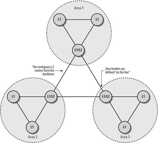
Routers can be defined as level 1, level 2, or both. In our illustrations, we abbreviate these designations as L1, L2, and L1/L2.
Under OSPF, Area 0 is the backbone. In an IS-IS network, contiguous level-2 area routers form the backbone. As shown in Figure 9-10, each area has a level-2 router (really it's a combination level-1 and level-2 router) that connects to another level-2 router, which forms our contiguous backbone. Since level-2 routers are members of one and only one area, unlike OSPF where ABR is a member of Area 0 as well as a "leaf" area, the area boundaries occur "on the line" as illustrated by the area circles in Figure 9-10.
Since level-2 routers interconnect areas, IP summarization occurs only on level-2 routers.
9.5.1.2. NSAP addressing
For TCP/IP networks, IP addresses must be unique. IS-IS is part of the OSI standard, and a Network Service Address Point (NSAP) address is the equivalent of an IP address for an OSI network; it must be unique throughout the IS-IS network in question. An NSAP address is a hexadecimal address with a length of up to 40 hexadecimal digits. It defines the address of the device (the system ID) and the link to the upper layer (the area number). NSAP addresses are used in ATM, as discussed in Chapter 6.
Table 9-1 shows how Cisco uses the NSAP address bytes in IS-IS.
|
Area ID |
System ID |
NSEL |
|---|---|---|
|
1-13 bytes |
6 bytes |
1 byte |
For a device, the Area ID is the router's IS-IS area and the System ID is the router identifier. On routers, the NSAP Selector (NSEL) is almost always set to 00.
Since our IS-IS network is small and not connected to others, we use a simplified addressing scheme designed to correspond to the way Cisco uses the address bytes. For our addresses, we'll convert and use our loopback IP address for our router. So, if our IP address was 192.168.21.1 (think of it as 192.168.021.001), our NSAP addresses look like this:
Where N is the area number (1, 2, or 3), and the rest of the NSAP is our IP address (1921.6802.1001). This works for us because device numbers are unique across areas. Another way of creating unique NSAP address is to use the Media Access Control (MAC) address.
Using the loopback naming convention is strictly our own way to help us in selecting the net addresses that we add to the configuration file. Since these addresses look like IP addresses, they serve as bridges between IS-IS and our IP addressing.
|

We configure the IS-IS network using the net command:
router isis
 net 49.0001.1921.6802.1001.00
Figure 9-10. IS-IS areas
Since a router is never in more than one area, you shouldn't need to define more than one net address for each router using IS-IS. Adding multiple area net addresses causes the areas to converge into one area. The rule is that you should never have more than one net address defined per router. And as always, there are exceptions to this rule. If you are merging or renumbering your areas, you will need to have multiple net addresses. But after the merger or renumbering is complete, you should be back to one net address defined for your IS-IS router.
9.5.1.3. Enabling an interface for IS-IS
IS-IS configuration is unique in that you define a routing process, then apply it to an interface instead of a network address. An interface will not participate in IS-IS routing unless configured to do so. In our example, we need to add the passive-interface loopback0 command so the loopback address is advertised via IS-IS, but the loopback interface does not participate in IS-IS advertisements:
router isis
 ! Build our NSAP address from the loopback's IP which is 172.16.1.7
 net 49.0001.1720.1600.1007.00
 passive-interface loopback0
!
interface ethernet0
 ip address 192.168.1.1 255.255.255.0
 ip router isis
9.5.2. IS-IS configuration example
Our sample configuration builds on an earlier example. In Figure 9-11, we can see the network with the area boundaries. This is the same network we used in our EIGRP example in Figure 9-3. However, this time we want to drop EIGRP from our network and run IS-IS only.
Figure 9-11. Network diagram of IS-IS sample configuration
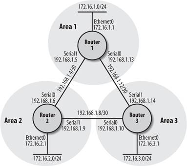
Here's the configuration for Router 1:
hostname router1
!
!
interface loopback0
 ip address 172.16.5.1 255.255.255.0
!
interface Ethernet0
 ip address 172.16.1.1 255.255.255.0
 ip router isis
!
interface Serial0
 bandwidth 125
 ip address 192.168.1.13 255.255.255.252
 ip router isis
!
interface Serial1
 bandwidth 125
 ip address 192.168.1.5 255.255.255.252
 ip router isis
!
router isis
 net 49.0001.1720.1600.5001.00
!
ip classless
Here's the configuration for Router 2:
hostname router2
!
interface loopback0
 ip address 172.16.6.1 255.255.255.0
!
interface Ethernet0
 ip address 172.16.2.1 255.255.255.0
 ip router isis
!
interface Serial0
 bandwidth 125
 ip address 192.168.1.6 255.255.255.252
 ip router isis
!
interface Serial1
 bandwidth 125
 ip address 192.168.1.9 255.255.255.252
 ip router isis
!
router isis
 net 49.0002.1720.1600.6001.00
!
ip classless
And here's the configuration for Router 3:
hostname router3
!
interface loopback0
 ip address 172.16.7.1 255.255.255.0
!
interface Ethernet0
 ip address 172.16.3.1 255.255.255.0
 ip router isis
!
interface Serial0
 bandwidth 125
 ip address 192.168.1.10 255.255.255.252
 ip router isis
!
interface Serial1
 bandwidth 125
 ip address 192.168.1.14 255.255.255.252
 ip router isis
!
router isis
 net 49.0003.1720.1600.7001.00
!
ip classless
If we do some show commands on Router 1, we can see the network is functioning, as we would expect:
router1#show ip route
Codes: C - connected, S - static, I - IGRP, R - RIP, M - mobile, B - BGP
 D - EIGRP, EX - EIGRP external, O - OSPF, IA - OSPF inter area
 N1 - OSPF NSSA external type 1, N2 - OSPF NSSA external type 2
 E1 - OSPF external type 1, E2 - OSPF external type 2, E - EGP
 i - IS-IS
, L1 - IS-IS level-1, L2 - IS-IS level-2, ia - IS-IS inter area
 * - candidate default, U - per-user static route, o - ODR
 P - periodic downloaded static route

Gateway of last resort is not set

 172.16.0.0/24 is subnetted, 3 subnets
C 172.16.1.0 is directly connected, Ethernet0
i L2 172.16.2.0 [115/20] via 192.168.1.6, Serial1
i L2 172.16.3.0 [115/20] via 192.168.1.14, Serial0
 192.168.1.0/30 is subnetted, 3 subnets
i L2 192.168.1.8 [115/20] via 192.168.1.14, Serial0
 [115/20] via 192.168.1.6, Serial1
C 192.168.1.12 is directly connected, Serial0
C 192.168.1.4 is directly connected, Serial1
9.5.3. Show Commands
The first command we'll use is show isis topology, which displays the IS-IS network topology as our current router sees it.
router1#show isis topology

IS-IS paths to level-1 routers
System Id Metric Next-Hop Interface SNPA
router2 **
router1 --

IS-IS paths to level-2 routers
System Id Metric Next-Hop Interface SNPA
router2 10 router2 Se1 *HDLC*
router1 --
router3 10 router3 Se0 *HDLC*
The second command we'll look at is show isis database, which shows all the IS-IS information we currently have. If you are troubleshooting your IS-IS network, you might want to look at show isis database detail, whichas the name suggestsprovides a greater degree of detail.
router1#show isis database
 IS-IS
 Level-1 Link State Database:
LSPID LSP Seq Num LSP Checksum LSP Holdtime ATT/P/OL
router2.00-00 0x00000003 0x7ABD 654 0/0/0
router1.00-00 * 0x00000002 0xBEE7 1091 1/0/0
IS-IS Level-2 Link State Database:
LSPID LSP Seq Num LSP Checksum LSP Holdtime ATT/P/OL
router2.00-00 0x00000051 0xEB34 1123 0/0/0
router1.00-00 * 0x00000005 0xA9D4 1175 0/0/0
router2.00-00 0x00000003 0xDF9D 1177 0/0/0
router3.00-00 0x00000005 0x84E6 1176 0/0/0
In this output, there are a few terms we should explain. First, the LSPID is the LSP Identifier, which the first six octets form the System ID of the router that originated the LSP. The Seq Num allows other systems to tell if they have the latest information from the source. The checksum is, of course, the checksum of the LSP packet. The holdtime is the amount of seconds that the LSP will remain valid. A value of zero means that the LSP has expired and is currently being purged from the router's databases. ATT is the attach bit, which indicates that the router is a level-2 router. Level-1 routers use this bit to find the nearest level-2 router. P stands for "repair partitions," which is a feature not supported by Cisco although it's reported here. Finally, the OL bit stands for "overload," which signals that the IS is congested. If the OL bit is set, other IS-IS routers will not use that router as a transit router. And only packets for devices directly connected to the overloaded router are sent to it.
Finally, show clns route shows the routing table from the CLNS point of view.
Router1#show clns route
Codes: C - connected, S - static, d - DecnetIV
 I - ISO-IGRP, i - IS-IS, e - ES-IS

C 49.0001.1111.1111.1111.00 [1/0], Local IS-IS NET
C 49.0001 [2/0], Local IS-IS Area
9.5.4. Authentication
We can enable IS-IS authentication by providing, directly on the interface, an IS-IS password for each level directly. The command isis password specifies the passwords for each level, as in this example:
interface serial0
 isis password ourAreaOnePasswd level-1
 isis password ourAreaTwoPasswd level-2
Now, our router cannot communicate via IS-IS until all its adjacent neighbors are configured with the same IS-IS passwords. You can also assign passwords to the area and the domain with the area-password and domain-password commands.
9.5.5. Metric Tuning
Other routing protocols assign a metric to an interface by using a calculation based on bandwidth or some other cost. IS-IS normally just gives every interface a metric of 10. In order to change this metric, you can provide an IS-IS metric directly on the interface with the rather obviously named isis metric command.
You can assign a metric value between the values 0 to 63. These values can be assigned to level 1, level 2, or both. For example, let's configured a metric of 23 for level 1 on Serial 0, and a metric of 25 for both on Serial 1.
interface serial0
 isis metric 23 level-1
interface serial1
 isis metric 25
9.5.6. Injecting a Default Route
The default-information originate command designates a given router as the default route for the network and announces that information to other routers in the network. For example, if we perform the command on Router 1:
router isis
 default-information originate
Now, the default route has been injected into the IS-IS routing. If we do a show ip route, we can see that the gateway of last resort, which is the default route to Router 1, is now set on Router 3. To put it another way, what you are seeing here is that we told Router 1 to become the default route for our network. This information has propagated via IS-IS to all our other routers. And now Router 3 has a default route, which is shown in the bolded output below. Before, Router 3 would not have a default route set.
router3#show ip route
Codes: C - connected, S - static, I - IGRP, R - RIP, M - mobile, B - BGP
 D - EIGRP, EX - EIGRP external, O - OSPF, IA - OSPF inter area
 N1 - OSPF NSSA external type 1, N2 - OSPF NSSA external type 2
 E1 - OSPF external type 1, E2 - OSPF external type 2, E - EGP
 i - IS-IS, L1 - IS-IS level-1, L2 - IS-IS level-2, ia - IS-IS inter area
 * - candidate default, U - per-user static route, o - ODR
 P - periodic downloaded static route

Gateway of last resort is 192.168.1.13 to network 0.0.0.0

 172.16.0.0/24 is subnetted, 3 subnets
i L2 172.16.1.0 [115/20] via 192.168.1.13, Serial1
i L2 172.16.2.0 [115/20] via 192.168.1.9, Serial0
C 172.16.3.0 is directly connected, Ethernet0
 192.168.1.0/30 is subnetted, 3 subnets
C 192.168.1.8 is directly connected, Serial0
C 192.168.1.12 is directly connected, Serial1
i L2 192.168.1.4 [115/20] via 192.168.1.9, Serial0
 [115/20] via 192.168.1.13, Serial1
i*L2 0.0.0.0/0 [115/10] via 192.168.1.13, Serial1
9.5.7. IS-IS Route Leaking
Route leaking sounds bad doesn't it? We'd better talk about how to plug those route leaks. Actually, it's more about route distribution than leaking. We've talked about how level-1 routers use level-2 routers to route packets that are outside their own area. A level-1 router knows about its own area and level-2 routers know how to connect their own area and the all the other areas.
Route leaking (or distributing) provides a way of letting level-1 areas know about level-2 routing information. The route information is "leaked" from level 2 to level 1. By having this information, the level-1 router can make better decisions as to which level-2 router to use to access outside areas.
Route leaking was added in IOS 12.1. Here's a sample route leaking configuration:
router isis
 redistribute isis ip level-2 into level-1 distribute-list 110
 metric-style wide
!
access-list 110 permit ip 172.16.0.0 0.0.255.255 any
access-list 110 permit ip 192.168.1.0 0.0.0.255 any
100 is the access list that defines the routes we want to leak. The meTRic-style wide command is optional, but Cisco highly recommends it.
Leaked routes appear in the route table with the ia notation (ia stands for "interarea"):
i ia 172.16.100.0/8 [115/138] via 192.168.1.13, Serial1
Now that this router has a "leaked" route, it can make better decisions about which level-2 router to access in order to reach the 172.16.100.0/8 subnet.
Getting Started
- Getting Started
- IOS User Modes
- Command-Line Completion
- Get to Know the Question Mark
- Command-Line Editing Keys
- Pausing Output
- show Commands
IOS Images and Configuration Files
- IOS Images and Configuration Files
- IOS Image Filenames
- The New Cisco IOS Packaging Model
- Loading Image Files Through the Network
- Using the IOS Filesystem for Images
- The Routers Configuration
- Loading Configuration Files
Basic Router Configuration
- Basic Router Configuration
- Setting the Router Name
- Setting the System Prompt
- Configuration Comments
- The Enable Password
- Mapping Hostnames to IP Addresses
- Setting the Routers Time
- Enabling SNMP
- Cisco Discovery Protocol
- System Banners
Line Commands
- Line Commands
- The line Command
- The Console Port
- Virtual Terminals (VTYs)
- Asynchronous Ports (TTYs)
- The Auxiliary (AUX) Port
- show line
- Reverse Telnet
- Common Configuration Items
Interface Commands
- Interface Commands
- Naming and Numbering Interfaces
- Basic Interface Configuration Commands
- The Loopback Interface
- The Null Interface
- Ethernet, Fast Ethernet, and Gigabit Ethernet Interfaces
- Token Ring Interfaces
- ISDN Interfaces
- Serial Interfaces
- Asynchronous Interfaces
- Interface show Commands
Networking Technologies
Access Lists
IP Routing Topics
- IP Routing Topics
- Autonomous System (AS) Numbers
- Interior and Exterior Gateway Protocols
- Distance-Vector and Link-State Routing Protocols
- Static Routes
- Split Horizon
- Passive Interfaces
- Fast Switching and Process Switching
Interior Routing Protocols
Border Gateway Protocol
- Border Gateway Protocol
- Introduction to BGP
- A Simple BGP Configuration
- Route Filtering
- An Advanced BGP Configuration
- Neighbor Authentication
- Peer Groups
- Route Reflectors
- BGP Confederacies
- BGP TTL Security
Quality of Service
- Quality of Service
- Marking
- Older Queuing Methods
- Modern IOS QoS Tools
- Congestion Avoidance
- Traffic Policing
- Traffic Shaping
- AutoQoS
- QoS Device Manager
Dial-on-Demand Routing
- Dial-on-Demand Routing
- Configuring a Simple DDR Connection
- Sample Legacy DDR Configurations
- Dialer Interfaces (Dialer Profiles)
- Multilink PPP
- Snapshot DDR
Specialized Networking Topics
- Specialized Networking Topics
- Bridging
- Hot Standby Routing Protocol (HSRP)
- Network Address Translation (NAT)
- Tunnels
- Encrypted Tunnels
- Multicast Routing
- Multiprotocol Label Switching (MPLS)
Switches and VLANs
- Switches and VLANs
- Switch Terminology
- IOS on Switches
- Basic Switch Configuration
- Trunking
- Switch Monitor Port for IDS or Sniffers
- Troubleshooting Switches
Router Security
- Router Security
- Securing Enable Mode Access
- Routine Security Measures
- Restricting Access to Your Router
Troubleshooting and Logging
Quick Reference
Appendix A Network Basics
Index
EAN: 2147483647
Pages: 1031
