Switch Terminology
Before we delve into the details on switches, we need to define some basic terminology.
14.1.1. Layer-2 and Layer-3 Switching
Most of this chapter focuses on the functionality of a layer-2 switch, a switch that operates at the Data Link layer of the OSI networking model (see the appendix for more details on the OSI model ). In other words, it switches frames at the MAC address level.
However, a new switch technology is coming to its own, layer 3 switching. From the name, it's easy to guess that these switches operate at the Networking layer of the OSI model, which means it switches based on IP address. As you can see, the line between routers and switches is becoming even less defined. However, you must remember that just because a switch can operate at layer 3 and above, that doesn't make it a router. In most cases, it means that the switch can do more advanced things, like filtering based on IP access lists. However, as we said earlier, Cisco has been releasing new devices that have both routing and switching capabilities; the lines between these devices are indeed blurring.
14.1.2. Learning MAC Addresses
In order to improve network performance, a switch needs to discover which hosts are connected to each port. Once it has that information, it can send the traffic for a specific host out only one interface instead of clogging the rest of the ports with unnecessary traffic. In other words, the switch sends traffic only to the host that needs it.
In order to do so, the switch must learn which port a host is on. It does this by taking the source MAC address of incoming packets. As the switch learns new MAC addresses, it adds them to the address table, which you can view with the command show mac-address-table.
When a switch doesn't know which port a host is on, it sends the traffic out all its active ports. It continues flooding traffic out all ports until the host finally replies. At that point, the switch can add the host's MAC address to its port table. Once the host is in the table, all traffic destined for that host is sent out only that port. Each port can support multiple MAC addresses. For example, if you have a hub plugged into a port, the switch will continue to store MAC addresses for all devices on the hub.
14.1.3. VLAN
A VLAN is a virtual local area network, a network segment defined by a switch or router. The switch connects all ports associated with a VLAN by its internal backbone, which is located inside the switch's hardware.
You can assign any series of ports on a switch to a VLAN. For example, on a 12-port switch, we could assign ports 1-6 to VLAN 2 and ports 7-12 to VLAN 3. Without extra configuration, these VLANs are logically separated. Devices in VLAN 2 cannot access devices in VLAN 3 and vice-versa. Each VLAN is basically a separate subnet.
Every VLAN is assigned a number, which identifies it with not only the local switch but other switches on the network. In the example we just mentioned, we said we had VLAN 2 and VLAN 3. When we talk about trunking later in this chapter, we'll see that two or more switches can be joined together and share VLAN information as if they were all on one switch.
14.1.4. Broadcast Domain
By default, a router doesn't forward broadcast packets. Since they don't forward broadcast packets, routers create broadcast domains . A broadcast domain is the area to which a broadcast is limited. Switches, by contrast, do forward broadcasts. A VLAN is by definition a broadcast domain, so even though a switch forwards broadcasts among devices in a particular VLAN, it doesn't forward them to other VLANs.
14.1.5. Collision Domain
As described earlier, a collision domain is defined by the number of devices on a particular network segment. The more devices you have on a segment, the more collisions that will occur. Luckily, each port of a switch is considered a separate collision domain. If you add only one device per switch port, this works very well. However, if you plug a hub into a switch port and then plug multiple devices into the hub, you just created a collision domain among the hosts on the segment, and the switch can't do anything to prevent collisions.
14.1.6. Spanning Tree Protocol
Switches and bridges implement the spanning tree protocol (STP) . This protocol has one primary purpose: loop prevention. A loop is basically a network transmission that keeps getting forwarded to other segments until it comes back to the original switch, which in turn forwards it again.
|

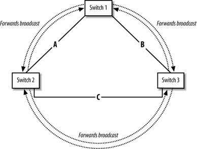
To better illustrate a loop, consider the diagram in Figure 14-1, which shows Switch 1 forwarding a broadcast.
Without STP, loops can easily occur because switches have no knowledge of which frames they've already forwarded. In this example, Switch 1 forwards the broadcast to Switch 2 and Switch 3. These switches forward the broadcast back out every port except for the port on which the broadcast was originally received. The broadcast then makes it back to Switch 1, which happily broadcasts the same frame because it has no way of knowing it has already sent that broadcast out. As the cycle repeats, more copies of the same broadcast are flooded onto the network. This scenario is called a broadcast storm .
Figure 14-1. Broadcast storm
STP prevents this very situation. In a nutshell, STP builds a tree structure out of our network by removing redundant links. At the logical center of this new tree structure is the root bridge . Every switch on the network can access any nonlocal MAC address by forwarding frames toward the root switch . This tree structurewith its removal of redundant linksprovides us with a loop-free network.
To understand how STP achieves thisfrom a very high levelwe must first explain some STP terminology, including Port States and BPDUs.
14.1.6.1. Spanning Tree Port States
Consider that every active switch port can have one of the following states:
- Disabled
- Blocking
- Listening
- Learning
- Forwarding
A port is considered disabled if it has no link status or has been shut down with an IOS command. Once a port is enabled (e.g., a cable is plugged in), the port is immediately placed into the blocking state, which allows the network to stabilize before making any changes to the network.
In the blocking state, the port does not participate in frame forwarding. The port remains in the blocking state for the duration of the forward-delay timer, which is 20 seconds. If the port does not hear any messages from another switch during this period, the port switches to the listening state.
Once in the listening state, port learning and frame forwarding are still both disabled. Instead, the switch is listening for messages from other switches in order to try to determine how the network topology is configured. The listening state lasts for 15 seconds, after which the switch moves to the learning state.
In the learning state, the switch listens for station location information to add into its Filtering Database (MAC address table.). Once this state is complete, the switch port goes into the forwarding state, which is the normal operating mode of a switch in which it forwards frames.
Here are the possible transitions of port states:
- initialization
 blocking
 - listening or disabled
- learning or disabled
- forwarding or disabled
- images/U2192.jpg border=0> disabled
As you can see from this list, the disabled state can occur at any time. When a change occurs on the network, each port repeats the blocking images/U2192.jpg border=0> listening
images/U2192.jpg border=0> learning
images/U2192.jpg border=0> forwarding cycle. The switch cannot place a port into the disabled state by itself. Only the administrator can move a port into and out of the disabled state.
|

14.1.6.2. Bridge Protocol Data Units
Every switch that speaks STP uses Bridge Protocol Data Units (BPDUs ) . BPDUs are messages that switches (and bridges) pass back and forth to each other in order to discover the STP network topology. Every switch sends out one of these multicast messages approximately every 2 seconds. These communications continue even after the STP network topology has been determined. If a change is detected on the network, the switches need to reconfigure the STP network.
With BPDUs, the switches establish (or elect) a few things on the network:
- root bridge
- root port
- designated port
14.1.6.3. STP selects the root bridge
Selecting the root bridge is an important process. All switches (like nearly all people) start out thinking they are the root bridge. As switches send out BPDUs, they attach their associated Bridge ID (BID) . The switch with the lowest BID wins and becomes the root bridge. Part of the BID message contains the switch's MAC address and a configurable priority value. If left to the default, the switch with the lowest MAC address has the winning BID. However, you can force a switch to win the election by simply setting its priority value to a lower number than the other switches.
The root bridge selection is important because all other STP calculations are based on that choice. The root bridge becomes the logical center of our new tree structure. And as we already said, any switch on the network can reach any nonlocal MAC address by forwarding frames toward this root bridge.
14.1.6.4. Selecting a root port and a designated port
Every switch that is not the root bridge must elect a root port. The root port is the port with the lowest "cost" back to the root bridge. Table 14-1 shows the costs associated with various link types.
|
Link type |
Cost |
|---|---|
|
Gigabit Ethernet |
4 |
|
Fast Ethernet |
19 |
|
Ethernet |
100 |
One problem with the selection of the root port is that this might not be the best or closest path to your intended destination, as we will see. In other words, just because the selected path is closest to the root bridge doesn't mean it's the closest to where you want to go.
A single designated port is elected for each LAN segment. One port on one switch is selected as the best path back to the root bridge. Unlike the root port, which is selected for every non-root switch, only one designated port is selected per segment. Basically, this port is the one that is placed in a forward state for the segment while the other ports on the segment are placed in blocking state. All ports that do not fall into the category of root port or designated port are put into blocking mode. By doing this, every segment (or LAN) is connected to every other segment on the network by only one path.
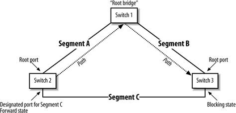
In Figure 14-2, the previous example has been updated with the root bridge, root ports, and designed ports. As you can see, the port connected to Switch 2 from Segment C is in forward state while the port connected to Switch 3 from Segment C is in the blocking state. This gives us only one path from Switch 2 to Switch 3, which is shown with the dotted line. Like we said before, we have only one path to the root bridge, and it's not exactly the best path to our destination, which in this case is Switch 3.
To put it another way, in order to get to our intended destination (Switch 3), we have to take the longer path to follow STP rules. While this isn't the best path, it's a small price to pay for a loop-free network.
Figure 14-2. Loop-free network, thanks to spanning tree
|
In summary, STP calculates three things to ensure a loop-free network:
- Root bridge election
- Root port on each non-root switch
- Designated port on each segment
By doing this, STP removes redundant links from our network. STP selects a root bridge and tells every other switch how to get back to it. Every switch can access any other nonlocal address simply by forwarding frames toward the root switch. These frames traverse the tree until they reach the final destination on our network.
In the next section, we'll learn how STP recovers if something breaks in our network. With convergence , STP rebuilds our network tree if a link goes down. In other words, one of the previously disabled redundant links will automatically become active.
14.1.6.5. Convergence in STP
Although our STP network topology has been selected, the switches keep communicating with BPDUs in case something changes. If something does change, like a switch is added or a current switch goes down, STP repeats the state cycle in order to converge the network. For example, if Switch 2 went down, Switch 3 would detect this and repeat the blocking, learning, listening state cycle, which would result in Switch 3 putting its port into the forwarding state. Once that happened, traffic would again flow from Segment C. The downside is that it takes about 50 seconds for this convergence to occur. (That works out to be 20 seconds in the blocking state if the root bridge can no longer be reached, 15 seconds for the listening state, and 15 more seconds for the learning state.)
14.1.6.6. Speeding up STP convergence
To most people, waiting 50 seconds for the switches to converge during a network change is unacceptable, so Cisco has provided a few methods to speed up STP convergence. The two methods that we cover are portfast and uplinkfast.
The portfast command tells the switch to enter the forwarding state immediately, bypassing the listening and learning states. This command should be used only on ports that are directly connected to a single device such as a server, workstation, or other end-user device (e.g., a network printer.) You should never use this on a port that connects to another switch because doing so will definitely break STP by introducing bridging loops.
 interface fa0/11
 description port to bobs PC
 spanning-tree portfast
On the (older) 1900 and 2820 series switches, the portfast command is called spantree start-forward, which is actually more descriptive of what the command does by putting the switch immediately into the forwarding state.
The uplinkfast command causes an immediate switchover to another available root port when the current root port fails. The new root port is immediately switched from the blocking state to the forwarding state. By doing this, we bypass the STP calculation of selecting a new root port. This command should be used only on switches that will never be selected as the root bridge because the command changes the bridge priority to 19152, a value that assures that it will never be selected as the root bridge.
 interface fa0/11
 spanning-tree uplinkfast
On the 1900 and 2820 series switches, this command is called spantree uplink-fast.
14.1.6.7. show spanning-tree
The show spanning-tree command gives you the output and status of spanning tree for the switch. In the highlighted sections of the sample output, we can see that the selected root port is port 8. If this switch were the root bridge, this line would read "We are the root of the spanning tree" because there is no root port on the root bridge. Why? Since the root port is always the port that leads toward the root bridge, we won't find any such ports on the root bridge itself.
As for the interface listing, we can see that Interface Fa0/1 is in the forwarding state. Other states you might see are disabled and blocking. Finally, the other important item is the BPDU counter, which tells us the number of BPDUs that were sent and received on this interface.
 switch2#show spanning-tree
 Spanning tree 1 is executing the IEEE compatible Spanning Tree protocol
 Bridge Identifier has priority 32768, address 0030.80ae.ce40
 Configured hello time 2, max age 20, forward delay 15
 Current root has priority 32768, address 0030.809b.9f80
 Root port is 8, cost of root path is 19
 Topology change flag not set, detected flag not set, changes 15
 Times: hold 1, topology change 35, notification 2
 hello 2, max age 20, forward delay 15
 Timers: hello 0, topology change 0, notification 0

 Interface Fa0/1 (port 1) in Spanning tree 1 is FORWARDING
 Port path cost 100, Port priority 128
 Designated root has priority 32768, address 0030.809b.9f80
 Designated bridge has priority 32768, address 0030.80ae.ce40
 Designated port is 1, path cost 19
 Timers: message age 0, forward delay 0, hold 0
 BPDU: sent 211437, received 0
Getting Started
- Getting Started
- IOS User Modes
- Command-Line Completion
- Get to Know the Question Mark
- Command-Line Editing Keys
- Pausing Output
- show Commands
IOS Images and Configuration Files
- IOS Images and Configuration Files
- IOS Image Filenames
- The New Cisco IOS Packaging Model
- Loading Image Files Through the Network
- Using the IOS Filesystem for Images
- The Routers Configuration
- Loading Configuration Files
Basic Router Configuration
- Basic Router Configuration
- Setting the Router Name
- Setting the System Prompt
- Configuration Comments
- The Enable Password
- Mapping Hostnames to IP Addresses
- Setting the Routers Time
- Enabling SNMP
- Cisco Discovery Protocol
- System Banners
Line Commands
- Line Commands
- The line Command
- The Console Port
- Virtual Terminals (VTYs)
- Asynchronous Ports (TTYs)
- The Auxiliary (AUX) Port
- show line
- Reverse Telnet
- Common Configuration Items
Interface Commands
- Interface Commands
- Naming and Numbering Interfaces
- Basic Interface Configuration Commands
- The Loopback Interface
- The Null Interface
- Ethernet, Fast Ethernet, and Gigabit Ethernet Interfaces
- Token Ring Interfaces
- ISDN Interfaces
- Serial Interfaces
- Asynchronous Interfaces
- Interface show Commands
Networking Technologies
Access Lists
IP Routing Topics
- IP Routing Topics
- Autonomous System (AS) Numbers
- Interior and Exterior Gateway Protocols
- Distance-Vector and Link-State Routing Protocols
- Static Routes
- Split Horizon
- Passive Interfaces
- Fast Switching and Process Switching
Interior Routing Protocols
Border Gateway Protocol
- Border Gateway Protocol
- Introduction to BGP
- A Simple BGP Configuration
- Route Filtering
- An Advanced BGP Configuration
- Neighbor Authentication
- Peer Groups
- Route Reflectors
- BGP Confederacies
- BGP TTL Security
Quality of Service
- Quality of Service
- Marking
- Older Queuing Methods
- Modern IOS QoS Tools
- Congestion Avoidance
- Traffic Policing
- Traffic Shaping
- AutoQoS
- QoS Device Manager
Dial-on-Demand Routing
- Dial-on-Demand Routing
- Configuring a Simple DDR Connection
- Sample Legacy DDR Configurations
- Dialer Interfaces (Dialer Profiles)
- Multilink PPP
- Snapshot DDR
Specialized Networking Topics
- Specialized Networking Topics
- Bridging
- Hot Standby Routing Protocol (HSRP)
- Network Address Translation (NAT)
- Tunnels
- Encrypted Tunnels
- Multicast Routing
- Multiprotocol Label Switching (MPLS)
Switches and VLANs
- Switches and VLANs
- Switch Terminology
- IOS on Switches
- Basic Switch Configuration
- Trunking
- Switch Monitor Port for IDS or Sniffers
- Troubleshooting Switches
Router Security
- Router Security
- Securing Enable Mode Access
- Routine Security Measures
- Restricting Access to Your Router
Troubleshooting and Logging
Quick Reference
Appendix A Network Basics
Index
EAN: 2147483647
Pages: 1031
