VoIP
Voice over IP (VoIP) might seem out of place among the other topics in this chapter. However, VoIP is becoming a major networking application and it's appearing everywhere. VoIP is running over Ethernet, frame relay, ISDN, ATM, DSL, cable, and other high-speed connections. When thought about that way, this is a great place to discuss it.[*]
[*] I cover VoIP briefly here, but if you are involved with setting up VoIP, you will doubtless want a book dedicated to that topic. I recommend Switching to VoIP by Theodore Wallingford (O'Reilly).
VoIP works by encoding analog voice signals into IP packets. These packets are sent across the network and reassembled and decoded at the other end back into analog sound. Since these packets take the same paths and share the same bandwidth with all other networking applications, it's important to configure quality of service (QoS) for voice traffic . Interruptions in voice conversations are extremely annoying (but thanks to cell phones, customers are far more tolerant than they used to be). With proper QoS settings, you can assure that voice traffic gets the highest priority. In other words, if you're sending a large file across your cable modem link, your VoIP phone will keep working without dropping bits of your sentences. Well, that's the hope anyway. For details on configuring QoS, see Chapter 11. If your setup is straightforward (that is, your only high-priority traffic is VoIP), take a look at AutoQoS, described at the end of that chapter.
6.5.1. VoIP Protocols
There are a few methods of VoIP configuration including H.323, Media Gateway Control Protocol (MGCP), and Session Initiation Protocol (SIP) .
6.5.1.1. H.323
The H.323 standard was the first standard for call control on Cisco VoIP devices. H.323 defines a set of protocols and components that support VoIP as well as real-time video. Specifically, H.323 uses Q.931 for signaling, H.245 for negotiation, and Registration Admission and Status (RAS) for session control. Other components of a VoIP setup under H.323 are the gatekeeper, gateway, MCU, and terminal. Here's a primer.
Gatekeeper
A device that manages other nodes on the H.323 network. There can only be one gatekeeper per zone. The gatekeeper's jobs include call setup, call waiting, and related services.
Gateway
A device that allows users of conventional phone lines to communicate with VoIP users.
MCU
MCU stands for Multipoint Control Unit, a device that is sometimes integrated into the gateway or gatekeeper. An MCU is a multi-call conference mixer, which allows conference calls to take place.
Terminal
An end user device such as an IP phone or PC phone.
6.5.1.2. MGCP
The MGCP standard followed H.323. It defines a distributed system that appears to outside networks as a single VoIP gateway. In order to configure MGCP, we need to define a call agent, which handles the call routing and setup. With Cisco VoIP, the call agent is an application called CallManager . In the MGCP example later in this chapter, we will show the IOS commands for configuring access to the CallManager. However, the CallManager itself is a sophisticated application with its own GUI and configuration; covering it in detail is beyond the scope of this book.
6.5.1.3. SIP
Session Initiation Protocol is an open standard that is quickly gaining popularity not only because it's an open standard but because it combines voice and Internet traffic and can coexist and interoperate with already deployed H.323 networks. Another reason that it's popular is that it is an ASCII (text) based protocol, just like HTTP and SMTP. For addresses, SIP uses an address of the format username@gateway, where the username can be an actual username or an E.164 address, the type of address used by ATM networks.
SIP is a peer-to-peer protocol with two types of peers: User Agent Clients (UAC) and User Agent Servers (UAS). The UAC is a client application that initiates the SIP request. And the UAS is a server application that responds to a request and answers on behalf of the user. Most SIP endpoints are capable of performing both UAC and UAS functions. SIP uses these requests and responses to set up a connection between the two endpoints.
For a list of all Cisco devices that support SIP, see http://www.cisco.com/warp/public/cc/techno/tyvdve/sip.
6.5.2. VoIP Terminology
Before we go into our examples, there is some more terminology that we need to discuss. Some of these terms we have already used.
PSTN
The Public Switched Telephone Network is the regular legacy phone system.
POTS
Plain Old Telephone Service, also known as analog phone service .
PBX
Private Branch Exchange. A private telephone network used inside an organization.
FXS
Foreign Exchange Station. An interface for directly connecting individual devices such as phones, faxes, or a regular PBX telephone system to the router.
FXO
Stands for Foreign Exchange Office. It is an interface that connects to the phone company. Basically, this connection is for trunk lines. For example, when you connect a PBX to the phone company, you plug the lines into the FXO ports on the PBX. The line is a trunk line, which handles many connections at once.
E&M interfaces
Oddly enough, E&M can stand for "ear and mouth" signaling, "recEive and transMit", or "Earth and Magnet." E&M interfaces are analog trunk connections to different systems, such as a PBX to a Central Office (CO).
RTP
RTP or Real-Time Transport Protocol is used for transmitting audio and video across IP networks. RTP is usually used for the actual call data in VoIP after all the signaling and call handling have been established. For example, SIP might be used to initiate the call between two endpoints, but RTP actually handles the voice transmission during the call.
6.5.3. Examples
Here are a few examples that cover some of the possibilities of VoIP on Cisco devices. The first example is an FXO gateway to the PSTN, which uses nothing more than the dial-peer connections to each office. A dial peer defines the connection type between the source and destination endpoints. Each connection that makes up a VoIP connection might have different "call legs" over the entire connection, and each leg of the connection might be a different dial-peer connection. For example, you might have source and destination POTS phones that are connected to routers over an IP network. The connection from the source POTS phone to the first router is a POTS dial peer. The connection from the source's router to the destination router over an IP network is a VoIP dial-peer. And finally, the connection from the destination router to the destination POTS connection is another POTS dial-peer.
6.5.3.1. FXO Gateway to PSTN
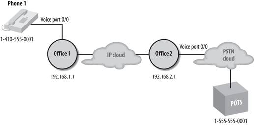
This example provides a way for our VoIP users in Office 1 to reach PSTN users at Office 2, which is outside their VoIP network (see Figure 6-4). Office 1 has a VoIP phone, which is assigned the number 1-410-555-0001. Office 2's router is directly connected to the PSTN via an FXO interface. The phone we want to be able to connect to at Office 2 has a phone number of 1-555-555-0001. With this configuration, the VoIP phone can call the POTS phones in Office 2 using the IP connection between the two routers, and vice versa.
Figure 6-4. FXO to PSTN Example
Here's the configuration for Office1's router :
hostname Office1
!
! Configure voice port 0/0
dial-peer voice 1 pots
 destination-pattern 14105550001
 port 0/0
!
! Office2 phone number
dial-peer voice 2 voip
 ! office2's phone number
 destination-pattern 15555550001
 ! The target is office2's router
 session target ipv4:192.168.2.1
 ip precedence 5
!
! Our wan connection
interface serial1
 ip address 192.168.1.1 255.255.255.0
Here's the configuration for Office2's router :
hostname Office2
!
! Configure voiceport 0/0
dial-peer voice 1 pots
 destination-pattern 15555550001
 port 0/0
!
! Configure office1 voip
dial-peer voice 2 voip
 ! office 1's phone number
 destination-pattern 14105550001
 ! the target is office1's router
 session target ipv4:192.168.1.1
 ip precedence 5

! Configure serial interface 0
interface serial0
 ip address 192.168.2.1 255.255.255.0
6.5.3.2. H.323 call routing
This example uses the same two-office setup as the previous example. However, in this case, each office is considered a zone and we configure call routing between the two zones. Each office has a gatekeeper machine and gateway machine. Office 1 will use 555-555-0002 and Office 2 will use 666-555-0002 as phone numbers. Each office has one phone plugged into port FXS 1/0 on each gateway device.
The gatekeeper's job is to group gateways into logical zones and perform call routing decisions between them. The gateway manages connections between the PTSN and our H.323 network.
Here's the configuration for Office1's gatekeeper:
hostname office1-gatekeeper
!
interface fastethernet 0/1
 ip address 192.168.1.2 255.255.255.0
 !
 gatekeeper
 ! Specify our local zone, which is controlled by our gatekeeper
 zone local office1zone xyzcorp.com
 ! Specify the remote zone (office2) and the remote keeper's IP address and
 port
 zone remote office2zone xyzcorp.com 192.168.2.2 1719
 ! Assign a prefix for the zones. The dots are wildcards
 zone prefix office1zone 555.......
 zone prefix office2zone 666.......
 ! Define the technology prefix, which is stripped before checking the zone
 prefix
 gw-type-prefix 1#* default technology
Here's the configuration for Office 1's gateway:
hostname office1-gateway
!
interface fastethernet0/0
 ip address 192.168.1.1 255.255.255.0
 h323-gateway voip interface
 ! Define the gatekeeper to work with (192.168.1.2)
 h323-gateway voip id office1zone ip addr 192.168.1.2 1718
 ! Define an alias for this gateway
 h323-gateway voip h323-id office1_gw
 ! again, specify the technology prefix
 h323-gateway voip tech-prefix 1#
!
dial-peer voice 1 voip
 ! The pattern for office 2, the .'s are wildcards
 destination pattern 666.......
 session target ras
!
dial-peer voice 2 pots
 destination-pattern 5555550002
 port 0/0
Here's the configuration for Office 2's gatekeeper:
hostname office2-gatekeeper
!
interface fastethernet 0/1
 ip address 192.168.2.2 255.255.255.0
 !
 gatekeeper
 zone local office2zone xyzcorp.com
 zone remote office1zone xyzcorp.com 192.168.1.2 1719
 zone prefix office1zone 555.......
 zone prefix office2zone 666.......

 gw-type-prefix 1#* default technology
Here's the configuration for Office 2's gatekeeper:
hostname office2-gateway
!
interface fastethernet0/0
 ip address 192.168.2.1 255.255.255.0
 h323-gateway voip interface
 ! Define the gatekeeper to work with (192.168.2.2)
 h323-gateway voip id office1zone ip addr 192.168.2.2 1718
 ! Define an alias for this gateway
 h323-gateway voip h323-id office2_gw
 h323-gateway voip tech-prefix 1#
 h323-gateway voip bind srcaddr 192.168.2.1
!
dial-peer voice 1 voip
 ! The pattern for office 1, the .'s are wildcards
 destination pattern 555.......
 session target ras
!
dial-peer voice 2 pots
 destination-pattern 6665550002
 port 0/0
You can use the show commands in Table 6-4 to verify H.323 configurations .
|
Command |
Displays |
|---|---|
|
show gateway |
The current status of the gateway |
|
show gatekeeper endpoints |
Status of all registered endpoints for a gatekeeper |
|
show gatekeeper zone status |
Status of all zones related to a gatekeeper |
|
show dial-peer voice |
The configuration for all VoIP and POTS dial peers |
6.5.3.3. MGCP call routing
In MGCP, the gateway configuration and the managed VoIP phones are configured from the CallManager software. On the gateway, we only need to identify the CallManager and enable MGCP. In Figure 6-5, we have a possible MGCP VoIP configuration. We have three managed phones, a CallManager box, and an MGCP gateway router.
Figure 6-5. MGCP Network Example
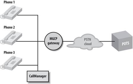
In Figure 6-5, the phones, CallManager, and the MGCP gateway are all connected on the Ethernet segment. The following example configures our MGCP gateway to identify the CallManager:
Hostname gateway
!
! Enable MGCP
mgcp
!
! This next line is enabled by default for MGCP. It causes the gateway to
! validate that it is in the same domain as the call manager box
mgcp validate domain-name
!
! Identify the call manager (whose IP address is 192.168.1.54)
mgcp call-agent 192.168.1.54 mgcp 0.1
!
! Identify the codec type and the dual-tone multifrequency (DTMF)
! DTMF really means touch-tone
mgcp dtmf-relay voip code all mode cisco
!
! Enabled this gateway to support call manager
ccm-manager mgcp
!
interface fastethernet0/1
 ip address 192.168.1.1 255.255.255.0
To verify the configuration, you can use the show mgcp command.
For more information on configuring the CallManager software, see http://www.cisco.com/en/US/products/sw/voicesw/ps556/index.html.
6.5.3.4. SIP Configuration for VoIP
If we want to configure SIP on a Cisco router, we need to configure our SIP user agent and our dial peers.
In this example, our router is a terminating SIP gateway, so we need to configure it as SIP user agent in order to receive incoming calls, which we do with the sip-ua command. Next, we'll configure our VoIP dial peers to use the already specified SIP server.
Hostname Office1
!
! enter the SIP User Agent mode
sip-ua
 ! The transport command sets the router up for SIP signalling.
 ! The type can be udp or tcp. udp is default
 transport udp
 ! Set the address of the SIP server
 sip-server ipv4:192.168.2.1
!
! Now configure a VoIP dial peer
dial-peer voice 1 voip
 ! define phone number associated with this peer
 destination-pattern 15555550001
 ! set the SIP transport type for the SIP user agent
 transport udp
 ! specify the SIP procotol type
 session protocol sipv2
 ! Tell the voice peer to use the sip server
 session target sip-server
We can also revisit our earlier example with Office1 and Office2 and use SIP. In this example, we enabled SIP using the exact same configuration as before, except that we added two commands, application session and session protocol sipv2, which are shown in bold:
! Office2 phone number
dial-peer voice 2 voip
 ! Enable standard session application for this dial peer
 application session
 ! office2's phone number
 destination-pattern 15555550001
 ! enable SIPv2 for this dial-peer
 session protocol sipv2
 ! The target is office2's router
 session target ipv4:192.168.2.1
 ip precedence 5
Getting Started
- Getting Started
- IOS User Modes
- Command-Line Completion
- Get to Know the Question Mark
- Command-Line Editing Keys
- Pausing Output
- show Commands
IOS Images and Configuration Files
- IOS Images and Configuration Files
- IOS Image Filenames
- The New Cisco IOS Packaging Model
- Loading Image Files Through the Network
- Using the IOS Filesystem for Images
- The Routers Configuration
- Loading Configuration Files
Basic Router Configuration
- Basic Router Configuration
- Setting the Router Name
- Setting the System Prompt
- Configuration Comments
- The Enable Password
- Mapping Hostnames to IP Addresses
- Setting the Routers Time
- Enabling SNMP
- Cisco Discovery Protocol
- System Banners
Line Commands
- Line Commands
- The line Command
- The Console Port
- Virtual Terminals (VTYs)
- Asynchronous Ports (TTYs)
- The Auxiliary (AUX) Port
- show line
- Reverse Telnet
- Common Configuration Items
Interface Commands
- Interface Commands
- Naming and Numbering Interfaces
- Basic Interface Configuration Commands
- The Loopback Interface
- The Null Interface
- Ethernet, Fast Ethernet, and Gigabit Ethernet Interfaces
- Token Ring Interfaces
- ISDN Interfaces
- Serial Interfaces
- Asynchronous Interfaces
- Interface show Commands
Networking Technologies
Access Lists
IP Routing Topics
- IP Routing Topics
- Autonomous System (AS) Numbers
- Interior and Exterior Gateway Protocols
- Distance-Vector and Link-State Routing Protocols
- Static Routes
- Split Horizon
- Passive Interfaces
- Fast Switching and Process Switching
Interior Routing Protocols
Border Gateway Protocol
- Border Gateway Protocol
- Introduction to BGP
- A Simple BGP Configuration
- Route Filtering
- An Advanced BGP Configuration
- Neighbor Authentication
- Peer Groups
- Route Reflectors
- BGP Confederacies
- BGP TTL Security
Quality of Service
- Quality of Service
- Marking
- Older Queuing Methods
- Modern IOS QoS Tools
- Congestion Avoidance
- Traffic Policing
- Traffic Shaping
- AutoQoS
- QoS Device Manager
Dial-on-Demand Routing
- Dial-on-Demand Routing
- Configuring a Simple DDR Connection
- Sample Legacy DDR Configurations
- Dialer Interfaces (Dialer Profiles)
- Multilink PPP
- Snapshot DDR
Specialized Networking Topics
- Specialized Networking Topics
- Bridging
- Hot Standby Routing Protocol (HSRP)
- Network Address Translation (NAT)
- Tunnels
- Encrypted Tunnels
- Multicast Routing
- Multiprotocol Label Switching (MPLS)
Switches and VLANs
- Switches and VLANs
- Switch Terminology
- IOS on Switches
- Basic Switch Configuration
- Trunking
- Switch Monitor Port for IDS or Sniffers
- Troubleshooting Switches
Router Security
- Router Security
- Securing Enable Mode Access
- Routine Security Measures
- Restricting Access to Your Router
Troubleshooting and Logging
Quick Reference
Appendix A Network Basics
Index
EAN: 2147483647
Pages: 1031
