Multicast Routing
Besides the fact that multicast packets have more than just one destination, they differ from most other technologies in one important way: multicast packets are routed based on their source address rather than their destination address. In the Appendix, we say that the multicast range is 224.0.0.0 through 239.255.255.255, which is also the class D address space. Packets destined for these addresses are flooded through the portion of our network where we configure multicast routing .
Multicast routing has two major configuration modes: dense mode and sparse mode. Before we discuss the two mode types and how they work, we need to review a few multicast concepts.
13.6.1. IGMP
IGMP stands for Internet Group Management Protocol. It is used by network hosts to tell the routers which multicast groups they would like to join by sending Join messages. The routers keep track of these multicast groups in a table. When hosts want to leave a group, they send a Leave message. The router manages this table efficiently. It doesn't keep track of every host that's interested in a multicast group. Rather, it keeps track of the fact that at least one node on the network wants packets from the requested multicast group. Since the router doesn't keep track of the number of hosts in a particular multicast group, it must respond a little differently to Leave messages. When a host sends a Leave message to the router, the router then asks all hosts on the network if anyone is still interested in that group. If no hosts respond to that request, the router removes that group from the list of forwarded multicast groups.
Later in this chapter, we'll review two other IGMP concepts when discussing multicasting with switches: IGMP snooping and Cisco Group Management Protocol (CGMP).
13.6.2. Reverse Path Forwarding
RPF stands for Reverse Path Forwarding. The main function of RPF is loop avoidance, which it achieves by applying several rules when dealing with multicast packets:
- An RPF interface is one that represents the best route back to the source IP address.
- If the router receives a packet on an interface that is the RPF interface back to the source of this packet, it forwards the packet to all other multicast interfaces.
- If the router receives a multicast packet on any other interface, it drops the packet.
By following these rules, the router attempts to avoid multicast loops.
Now we are ready to look at the modes of multicast routing: dense mode , sparse mode, and sparse-dense mode, which is far less confusing than it sounds.
13.6.3. Dense Mode
For the dense mode, a "push" model is used to flood multicast traffic through the network. Dense mode assumes everyone wants to receive multicast packets, so it floods the packets down all interfaces that are configured for multicast support. It then prunes the ones that explicitly reject a given group. This push and pruning method is used to develop source-based delivery trees.
Dense mode is suited to local LANs and high-bandwidth connections. However, it can be run on low-bandwidth networks if the multicast application is economical or if a large part of the network is expected to join the group.
13.6.3.1. Configuring multicast for dense mode
To configure multicasting routing, we first need to enable it on the router with the global ip multicast-routing command. This command is required for both dense and sparse mode.
Before we examine the router configurations, let's look at the example network. Figure 13-5 shows our humble network.
After configuring the router with multicast routing, we configure each interface we want to participate in multicast sessions. To do this, we'll use the ip pim dense-mode command (pim indicates "Protocol Independent Multicasting"). And in our network, we want every interface to participate in multicasting. So the configurations will look like this:
 hostname router1
 !
 ip multicast-routing
 !
 interface serial0
 ip pim dense-mode
 ip address 192.168.2.1 255.255.255.0
 !
 interface serial1
Figure 13-5. Example multicast network
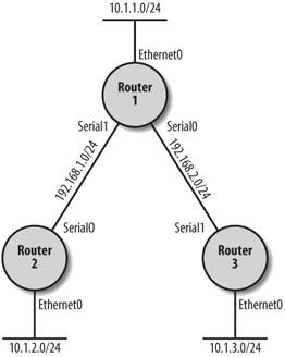
 ip pim dense-mode
 ip address 192.168.1.1 255.255.255.0
 !
 interface ethernet0
 ip pim dense-mode
 ip address 10.1.1.1 255.255.255.0
 !
 router eigrp 100
 network 10.0.0.0
 network 192.168.1.0
 network 192.168.2.0
For Router 2 and Router 3, we are going to use an additional command: ip igmp join-group because we have no hosts on our network to demonstrate the joining of groups. In other words, there are no hosts sending IGMP messages, so we need this command to make the routers join the groups explicitly and make our show command output meaningful in this example. This command causes our router to respond as a multicast host on its own interface. By doing this, we'll be able to ping the multicast address and verify that multicast routing is indeed working.
Here's the configuration for Router 2:
 hostname router2
 !
 ip multicast-routing
 !
 interface serial0
 ip pim dense-mode
 ip address 192.168.1.2 255.255.255.0
 !
 interface ethernet0
 ip pim dense-mode
 ip address 10.1.2.1 255.255.255.0
 ip igmp join-group 239.0.0.0
 !
 router eigrp 100
 network 10.0.0.0
 network 192.168.1.0
 network 192.168.2.0
And here's the configuration for Router 3:
 hostname router3
 !
 ip multicast-routing
 !
 interface serial1
 ip pim dense-mode
 ip address 192.168.2.2 255.255.255.0
 clockrate 64000
 !
 interface ethernet0
 ip pim dense-mode
 ip address 10.1.3.1 255.255.255.0
 ip igmp join-group 239.0.0.0
 !
 router eigrp 100
 network 10.0.0.0
 network 192.168.1.0
 network 192.168.2.0
To show that multicast is working, we can ping a multicast address and see who responds:
 router1#ping 239.0.0.0

 Type escape sequence to abort.
 Sending 1, 100-byte ICMP Echos to 239.0.0.0, timeout is 2 seconds:

 Reply to request 0 from 192.168.1.2, 24 ms
 Reply to request 0 from 192.168.2.2, 36 ms
This works because of the ip igmp join-group command we added to Router 2 and Router 3. If we didn't use this command, those interfaces would not respond to this ping. A router isn't normally a multicast client except for routing protocols that use multicast for distributing routing information. In our little network, we have no multicast clients to ping, so this trick makes our simple example work. You wouldn't need this command in a normal environment. Also, be aware that join-group is considered a dangerous command because it can lead to multicast routing loops if not used with care. If you configure a static IGMP join on an interface, the router will always forward packets for that group out that interface, even if the router would normally prune this interface from the RPF tree. But as we said, we needed it for this example to demonstrate multicasting packets.
Two major show commands that display the state of our multicast configuration are show ip pim interface and show ip pim neighbor. The show ip pim interface command displays the interfaces that are enabled for multicast. (D in the following output indicates dense mode.) And the neighbor commands show the multicast neighbors for this router.
 router1#show ip pim interface

 Address Interface Ver/ Nbr Query DR DR
 Mode Count Intvl Prior
 10.1.1.1 Ethernet0 v2/D 0 30 1 10.1.1.1
 192.168.2.1 Serial0 v2/D 1 30 1 0.0.0.0
 192.168.1.1 Serial1 v2/D 1 30 1 0.0.0.0

 router1#show ip pim neighbor
 PIM Neighbor Table
 Neighbor Interface Uptime/Expires Ver DR
 Address Priority
 192.168.2.2 Serial0 00:36:28/00:01:20 v2 1 (BD)
 192.168.1.2 Serial1 00:37:47/00:01:31 v2 1 (BD)
 router1#
Finally, the show ip mroute command displays the multicast routing table. In this output, we can see which multicast networks are being used and the various flags. In this output, all our interfaces are in dense mode:
 router1#show ip mroute
 IP Multicast Routing Table
 Flags: D - Dense, S - Sparse, B - Bidir Group, s - SSM Group, C - Connected,
 L - Local, P - Pruned, R - RP-bit set, F - Register flag,
 T - SPT-bit set, J - Join SPT, M - MSDP created entry,
 X - Proxy Join Timer Running, A - Advertised via MSDP, U - URD,
 I - Received Source Specific Host Report
 Outgoing interface flags: H - Hardware switched
 Timers: Uptime/Expires
 Interface state: Interface, Next-Hop or VCD, State/Mode

 (*, 224.0.1.40), 00:19:08/00:00:00, RP 0.0.0.0, flags: DJCL
 Incoming interface: Null, RPF nbr 0.0.0.0
 Outgoing interface list:
 Ethernet0, Forward/Dense, 00:19:08/00:00:00
 Serial0, Forward/Dense, 00:19:08/00:00:00
 Serial1, Forward/Dense, 00:19:08/00:00:00

 (*, 239.0.0.0), 00:12:10/00:02:59, RP 0.0.0.0, flags: D
 Incoming interface: Null, RPF nbr 0.0.0.0
 Outgoing interface list:
 Serial0, Forward/Dense, 00:12:10/00:00:00
 Serial1, Forward/Dense, 00:12:10/00:00:00

 (192.168.1.1, 239.0.0.0), 00:02:19/00:01:10, flags: T
 Incoming interface: Serial1, RPF nbr 192.168.1.2
 Outgoing interface list:
 Serial0, Forward/Dense, 00:02:19/00:00:00

 (192.168.2.1, 239.0.0.0), 00:01:34/00:01:55, flags: T
 Incoming interface: Serial0, RPF nbr 192.168.2.2
 Outgoing interface list:
 Serial1, Forward/Dense, 00:01:34/00:00:00
Another entry that you see in the output of this command is RPF, which we described earlier.
13.6.4. Sparse Mode
Unlike dense mode, sparse mode forwards multicast packets only to receivers that have actually joined the multicast group. (Dense mode just assumes everyone wants the packets and floods them everywhere until it receives rejection requests from clients and they are pruned from the tree.) So how do receivers join the multicast group? Once again, the hosts use IGMP to communicate with the router. But this time the router sends multicast traffic to a designated Rendezvous Point (RP).
An RP is a selected router on the network that all the other routers will use for multicast traffic. When a node sends a Join message to a router, the router will send that Join message to the nearest RP router. The RP router keeps track of the host and the multicast group in a shared source tree. When multicast traffic enters the network, the router that receives it forwards the traffic to the RP. The RP looks at its shared source tree and forwards the packet to all routers on the network with hosts that have joined the packet's multicast group. This shared source tree method is different from dense mode, in which each router maintains a separate tree of sources and multicast groups.
There can be multiple RPs on a multicast network. And RPs can defined statically or dynamically. For our first configuration, we'll look at static RP definitions.
13.6.4.1. Configuring multicast for sparse mode
Just as with dense mode, we'll need to enable multicast routing globally on the router with the ip multicast-routing command. After that, each interface gets ip pim sparse-mode command, which is much like our dense mode configuration. The only new item for sparse mode is defining the RP, which we are doing statically. For this configuration, we have selected Router 1 as the RP. No extra configuration is required on Router 1 to make it the RP because any router assumes that it is an RP once it starts receiving incoming join messages that contain one of its own multicast-enabled interfaces.
All we need to do is define the RP on Router 2 and Router 3 with the ip pim rp-address command. We will use Ethernet0 as the address on Router 1. Also, the interface we choose must have ip pim sparse-mode configured, even loopback interfaces.
Here's the configuration for Router 1:
 hostname router1
 !
 ip multicast-routing
 !
 interface serial0
 ip pim sparse-mode
 ip address 192.168.2.1 255.255.255.0
 !
 interface serial1
 ip pim sparse-mode
 ip address 192.168.1.1 255.255.255.0
 !
 interface ethernet0
 ip pim sparse-mode
 ip address 10.1.1.1 255.255.255.0
 !
 router eigrp 100
 network 10.0.0.0
 network 192.168.1.0
 network 192.168.2.0
Here's the configuration for Router 2:
 hostname router2
 !
 ip multicast-routing
 !
 ! Define our RP for our network
 ip pim rp-address 10.1.1.1
 !
 interface serial0
 ip pim sparse-mode
 ip address 192.168.1.2 255.255.255.0
 !
 interface ethernet0
 ip pim sparse-mode
 ip address 10.1.2.1 255.255.255.0
 ip igmp join-group 239.0.0.0
 !
 router eigrp 100
 network 10.0.0.0
 network 192.168.1.0
 network 192.168.2.0
And here's the configuration for Router 3:
 hostname router3
 !
 ip multicast-routing
 !
 ! Define our RP for our network
 ip pim rp-address 10.1.1.1
 !
 interface serial1
 ip pim sparse-mode
 ip address 192.168.2.2 255.255.255.0
 !
 interface ethernet0
 ip pim sparse-mode
 ip address 10.1.3.1 255.255.255.0
 ip igmp join-group 239.0.0.0
 !
 router eigrp 100
 network 10.0.0.0
 network 192.168.1.0
 network 192.168.2.0
The output for show ip mroute lists our defined RP:
 router1#show ip mroute
 IP Multicast Routing Table
 Flags: D - Dense, S - Sparse, B - Bidir Group, s - SSM Group, C - Connected,
 L - Local, P - Pruned, R - RP-bit set, F - Register flag,
 T - SPT-bit set, J - Join SPT, M - MSDP created entry,
 X - Proxy Join Timer Running, A - Advertised via MSDP, U - URD,
 I - Received Source Specific Host Report
 Outgoing interface flags: H - Hardware switched
 Timers: Uptime/Expires
 Interface state: Interface, Next-Hop or VCD, State/Mode

 (*, 224.0.1.40), 00:04:24/00:00:00, RP 10.1.1.1, flags: SJCL
 Incoming interface: Null, RPF nbr 0.0.0.0
 Outgoing interface list:
 Serial0, Forward/Sparse, 00:04:24/00:03:23
 Serial1, Forward/Sparse, 00:01:25/00:02:30

 (*, 239.0.0.0), 00:01:36/00:03:25, RP 10.1.1.1, flags: S
 Incoming interface: Null, RPF nbr 0.0.0.0
 Outgoing interface list:
 Serial1, Forward/Sparse, 00:01:36/00:02:30
 Serial0, Forward/Sparse, 00:00:04/00:03:25

 router1#ping 239.0.0.0

 Type escape sequence to abort.
 Sending 1, 100-byte ICMP Echos to 239.0.0.0, timeout is 2 seconds:

 Reply to request 0 from 192.168.1.2, 56 ms
 Reply to request 0 from 192.168.1.2, 112 ms
13.6.4.2. Auto-RP configuration and sparse-dense mode
Statically defining the RP in our little network is fine, but for larger networks, static defining anything isn't really a good idea. Luckily for us there is Auto-RP, which allows the routers to learn who the RP is dynamically. All we do is configure the router we want to be the RP and let it announce itself to other routers.
In order to use Auto-RP, we need to change all our modes from sparse mode to sparse-dense mode. Sparse-dense mode isn't as contradictory as it might sound. Basically, it allows the interface to operate in dense mode until an RP is selected. Once the RP is selected, the group begins operating in sparse mode and our interface switches to sparse mode as well. In other words, dense mode is needed to accept the RP announcements. Once the RP is selected, we are back to sparse mode.
Now, on Router 1 we are going to define a loopback interface and then let the router announce itself as the RP.
 interface loopback0
 ip address 10.2.1.1 255.255.255.0
 ip pim sparse-dense-mode
 !
 ! Set the auto-rp announcements to have a scope of 16.
 ! The scope is the Time-To-Live, which limits how far
 ! they can travel. Choose a number large enough to cover
 ! your pim domain.
 ip pim send-rp-announce loopback0 scope 16
 ip pim send-rp-discovery scope 16
On all other routers, make sure our interfaces are in sparse-dense mode:
 interface serial0
 ip pim sparse-dense-mode
In order for the RP selection to begin, we need to start our multicast software. In this case, all we need to do is ping 239.0.0.0:
 router1#ping 239.0.0.0

 Type escape sequence to abort.
 Sending 1, 100-byte ICMP Echos to 239.0.0.0, timeout is 2 seconds:

 Reply to request 0 from 192.168.2.2, 64 ms
 Reply to request 0 from 192.168.1.2, 100 ms
Now, we can see the RP selection for 239.0.0.0:
 router1#show ip mroute
 IP Multicast Routing Table
 Flags: D - Dense, S - Sparse, B - Bidir Group, s - SSM Group, C - Connected,
 L - Local, P - Pruned, R - RP-bit set, F - Register flag,
 T - SPT-bit set, J - Join SPT, M - MSDP created entry,
 X - Proxy Join Timer Running, A - Advertised via MSDP, U - URD,
 I - Received Source Specific Host Report
 Outgoing interface flags: H - Hardware switched
 Timers: Uptime/Expires
 Interface state: Interface, Next-Hop or VCD, State/Mode

 (*, 239.0.0.0), 00:01:39/00:02:59, RP 10.5.1.1, flags: S
 Incoming interface: Null, RPF nbr 0.0.0.0
 Outgoing interface list:
 Serial0, Forward/Sparse-Dense, 00:00:40/00:02:49
 Serial1, Forward/Sparse-Dense, 00:00:39/00:02:50
13.6.4.3. BSR
Bootstrap Router (BSR) was introduced in PIMv2. It operates much like Auto-RP except that BSR is an open standard while Auto-RP is proprietary to Cisco. Also, with BSR, you need only sparse mode. There is no need for sparse-dense mode with BSR.
You can use BSR instead of Auto-RP just by using the following commands:
 ip pim bsr-candidate loopback 0 1
 ip pim rp-candidate loopback 0
In this case, we configured the BSR and RP to be the same router. You can configure them on different routers.
13.6.5. Cisco Group Management Protocol (CGMP)
CGMP works with switches to limit the forwarding of multicast packets to the ports with multicast clients. As clients join and leave multicast groups, the switch dynamically updates its database of multicast ports. The major advantage of thisbesides keeping multicast configuration simpler on the switch sideis that this protocol reduces the amount of multicast traffic on user segments by sending multicast packets only to the ports that actually require it.
Without CGMP, a switch has to listen to every single IGMP packet using what's called IGMP snooping . In IGMP snooping, the switch listens for every IGMP packet and analyzes it in order to determine how to switch the packet. To do this, the switch's management module has to be a member of every multicast group all the time, which can result in significant overhead for the switch.
CGMP takes advantage of the fact that the router has to listen to IGMP anyway. The router can use CGMP to just pass local membership information over to the switch, which eliminates the need for the switch to perform IGMP snooping.
In the end, the goal of CGMP and IGMP snooping is to allow the switch to know how to forward multicast packets to specific devices that are members of the multicast groups.
CGMP is a proprietary Cisco protocol that requires both Cisco routers and Cisco (Catalyst) switches. On almost all Cisco switches, CGMP is enabled by default. There is one notable exception, however; the 5000 series requires the following command to enable CGMP:
set cgmp enable
On the router side, you configure CGMP and IGMP with the following commands:
 ip cgmp
 ip igmp
Getting Started
- Getting Started
- IOS User Modes
- Command-Line Completion
- Get to Know the Question Mark
- Command-Line Editing Keys
- Pausing Output
- show Commands
IOS Images and Configuration Files
- IOS Images and Configuration Files
- IOS Image Filenames
- The New Cisco IOS Packaging Model
- Loading Image Files Through the Network
- Using the IOS Filesystem for Images
- The Routers Configuration
- Loading Configuration Files
Basic Router Configuration
- Basic Router Configuration
- Setting the Router Name
- Setting the System Prompt
- Configuration Comments
- The Enable Password
- Mapping Hostnames to IP Addresses
- Setting the Routers Time
- Enabling SNMP
- Cisco Discovery Protocol
- System Banners
Line Commands
- Line Commands
- The line Command
- The Console Port
- Virtual Terminals (VTYs)
- Asynchronous Ports (TTYs)
- The Auxiliary (AUX) Port
- show line
- Reverse Telnet
- Common Configuration Items
Interface Commands
- Interface Commands
- Naming and Numbering Interfaces
- Basic Interface Configuration Commands
- The Loopback Interface
- The Null Interface
- Ethernet, Fast Ethernet, and Gigabit Ethernet Interfaces
- Token Ring Interfaces
- ISDN Interfaces
- Serial Interfaces
- Asynchronous Interfaces
- Interface show Commands
Networking Technologies
Access Lists
IP Routing Topics
- IP Routing Topics
- Autonomous System (AS) Numbers
- Interior and Exterior Gateway Protocols
- Distance-Vector and Link-State Routing Protocols
- Static Routes
- Split Horizon
- Passive Interfaces
- Fast Switching and Process Switching
Interior Routing Protocols
Border Gateway Protocol
- Border Gateway Protocol
- Introduction to BGP
- A Simple BGP Configuration
- Route Filtering
- An Advanced BGP Configuration
- Neighbor Authentication
- Peer Groups
- Route Reflectors
- BGP Confederacies
- BGP TTL Security
Quality of Service
- Quality of Service
- Marking
- Older Queuing Methods
- Modern IOS QoS Tools
- Congestion Avoidance
- Traffic Policing
- Traffic Shaping
- AutoQoS
- QoS Device Manager
Dial-on-Demand Routing
- Dial-on-Demand Routing
- Configuring a Simple DDR Connection
- Sample Legacy DDR Configurations
- Dialer Interfaces (Dialer Profiles)
- Multilink PPP
- Snapshot DDR
Specialized Networking Topics
- Specialized Networking Topics
- Bridging
- Hot Standby Routing Protocol (HSRP)
- Network Address Translation (NAT)
- Tunnels
- Encrypted Tunnels
- Multicast Routing
- Multiprotocol Label Switching (MPLS)
Switches and VLANs
- Switches and VLANs
- Switch Terminology
- IOS on Switches
- Basic Switch Configuration
- Trunking
- Switch Monitor Port for IDS or Sniffers
- Troubleshooting Switches
Router Security
- Router Security
- Securing Enable Mode Access
- Routine Security Measures
- Restricting Access to Your Router
Troubleshooting and Logging
Quick Reference
Appendix A Network Basics
Index
EAN: 2147483647
Pages: 1031
