Multiprotocol Label Switching (MPLS)
Multiprotocol Label Switching (MPLS) integrates layer 2 information with layer 3 routing, which means that MPLS offers the performance of switching with all the intelligence of routing.
13.7.1. MPLS Terminology
Before we start talking about the advantages of MPLS and how it operates, we need to define a few terms:
MPLS domain
A group of routers in an MPLS "cloud," that is, where all are running MPLS.
LSR
Label Switching Router. A router within our MPLS domain that is running MPLS.
LSP
Label Switched Path. The path the packet will take along our MPLS routers.
Ingress router
The first router in the MPLS domain. It attaches the MPLS tag to our packet.
Egress router
The last router in the MPLS domain for a packet's path. The egress router strips the MPLS tag from the packet before forwarding it to its final destination.
13.7.2. How Does It Work?
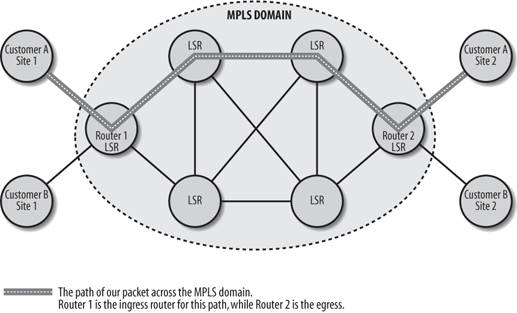
An MPLS domain is a group of LSR routers, as shown in Figure 13-6. By using MPLS, the routers are able to route and switch packets based on the label (tag) that the packet has been given. (This label is appended to the packet by the ingress router and removed by the egress router.) This label identifies the flow between the two endpoints in the MPLS domain. In this case, the path is from Customer A Site 1 to Customer A Site 2.
So, you might be asking, what's the big deal? It attaches labels to packets; so what? Well, here is the big deal: as a packet travels along the path, the routers do not need to examine or process the IP header of the packet nor do the routers need to make routing decisions for each packet. The routers simply look at the packet's label to make the "routing decision." Before we were using MPLS, each router had to examine the packet's IP information and then look up the routing tables, which is a waste of resources. Why have each router repeat the same steps?
One common analogy used to explain MPLS compares it to the post office. (I almost hate to use it here because I see it so often, but I can't think of a better analogy.) When the post office receives a piece of mail, it's processed just once at the first sorting facility that it reaches. At this facility, the letter is scanned and labeled with a tag. This tag identifies the path this letter will take to its destination. As the letter travels to a new facility, the letter doesn't need to be reread and routed; only the tag needs to be processed. The tag points to a path from the one facility to the next. If each sorting facility reread the letter's address, mail delivery would be highly inefficient. The same thing goes for MPLS: having each router along the MPLS domain reread the packet's IP address information and make a routing decision is a waste. MPLS saves routing resources by making the decision once and letting routers farther down the path make routing decisions based solely on a simple label.
To better understand, we could look at the MPLS process. The first LSR router in our MPLS domain is the one that examines the packet's IP information and attaches the MPLS tag to the packet. As each LSR router along the path receives the labeled packet, the following steps occur:
- The MPLS label is examined in the packet.
- The packet is forwarded to the next LSR.
- If this is the last router in the MPLS domain (the egress router), the MPLS label is stripped and the packet is forwarded to its destination.
Figure 13-6. MPLS network example
13.7.3. Configuring MPLS
There isn't much to a simple MPLS configuration; we just need to enable CEF (Cisco Express Forwarding) on the router with the global command ip cef and enable MPLS with the older interface command tag-switching ip.
 ! Enable Cisco Express Forwarding
 ip cef
 !
 ! Enable interface for MPLS
 interface fastethernet0/1
 tag-switching ip
As of IOS version 12.0, the mpls command replaces the tag-switching command. So our configuration becomes:
 ! Enable Cisco Express Forwarding
 ip cef
 !
 ! Enable interface for MPLS
 interface fastethernet0/1
 mpls ip
13.7.3.1. Incrementally deploying MPLS
If you want to deploy MPLS slowly, you can do so two routers at a time. For example, we can start our migration to MPLS by adding the following configurations on just two of our interconnected routers. After we have the two routers running MPLS, we can move out and configure the next connected router on our path. We'll start at the core with two adjacent routers. Each time we move out and implement MPLS on more routers, we are defining new ingress and egress routers and expanding our core.
Here's the configuration for Router 1:
 ip cef
 ! Connection to Router 1
 interface fastethernet0/1
 mpls ip
Here's the configuration for Router 2:
 ip cef
 ! Connection to Router 2
 interface fastethernet0/2
 mpls ip
Now just keep going to the next router until the entire MPLS domain is complete.
13.7.3.2. Verifying the MPLS configuration
We can verify our MPLS configuration with the following commands: show mpls interfaces, which displays all the MPLS information for interfaces configured for MPLS, and show mpls forwarding-table, which displays the contents of the MPLS forwarding information base. In the following output, we can see which interfaces have MPLS enabled.
 router# show mpls interfaces
 Interface IP Tunnel Operational
 Ethernet0/1/1 Yes (tdp) No No
 Ethernet0/1/2 Yes (tdp) No No
 Ethernet0/1/3 Yes (tdp) Yes Yes
 POS2/0/0 Yes (tdp) No No
 ATM0/0.1 Yes (tdp) No No (ATM labels)
 ATM1/0.1 Yes (ldp) No Yes (ATM labels)
And with the show mpls forwarding-table command, we can see the local tag and the outgoing tag. The outgoing tag is the label assigned by the next hop router. It is either untagged or pop tag. Untagged means there is no label for the destination from the next hop or that label switching isn't available on the outgoing interface. Pop tag means that the next hop advertised an implicit NULL label for the destination, which made this router pop the top label.
 Router# show mpls forwarding-table
 Local Outgoing Prefix Bytes tag Outgoing Next Hop
 tag tag or VC or Tunnel Id switched interface

 26 Untagged 10.1.0.0/16 0 Et0/1/1 192.168.32.4
 28 1/30 10.2.0.0/16 0 AT0/0.1 point2point
 29 Pop tag 10.3.0.0/16 0 Hs5/0 point2point
13.7.4. MPLS VPN
As if MPLS were not already a big-enough feature, there is one more major part to describe: MPLS VPNs. These VPNs allow you to create totally separate VPNs across an MPLS domain. These VPNs are seen as private intranets within each domain, so there is no concern about one customer's traffic mixing with another's.
MPLS VPNs are connectionless, scaleable, easy to create, and support technologies such as multicast, QoS, and VoIP. Since they are connectionless, the biggest advantages are that they are easier to build and manage versus conventional VPNs, take up less CPU and memory on the routers, and offer faster switching. For an MPLS VPN to operate, we need to understand some VPN router types , as shown in Table 13-1.
|
Router type |
Meaning |
|---|---|
|
P |
Provider's core router |
|
PE |
Provider's edge router |
|
CE |
Customer's edge router |
|
C |
Customer's router |
Our network diagram in Figure 13-6 shows PE routers Router 1 and Router 2. All the other LSR routers in our Domain are Ps. The CE and C routers would be at the customer site. For our example configuration, we configure only the PE routers for the VPNs.
Each MPLS VPN is associated with a VPN routing/forwarding (VRF) instance. A VRF defines the VPN membership of a remote site to the PE router. For each VRF, a separate routing table and CEF table is managed, which keeps the outside traffic from entering our VPN and information leaving our VPN.
For this example, let's assume our BGP AS is 1000 and that Router 1 has IP address 10.1.1.4 and Router 2 has 10.1.1.6. To set up our VPNs, we are going to define the VPN with the VRF command and then configure BGP.
On our PE routers (Router 1 and Router 2), we need to define our VPNs. To do this, we create two VRFs with the ip vrf command and apply these VRFs to our interfaces with the ip vrf forwarding command. The route distinguisher is our AS number followed by another number, which in this case is 1 for Customer A and 2 for Customer B.
 hostname router1
 !
 ! Required for MPLS
 ip cef
 !
 ! Define our VPN routing instance for customerA
 ip vrf customerA
 rd 1000:1
 route-target both 1000:1
 !
 ! Define our VPN Routing instance for customerB
 ip vrf customerB
 rd 1000:2
 route-target both 1000:2
 !
 ! Set up interface as a VRF link to customer router (CE)
 interface fastethernet0/0
 ip vrf forwarding customerA
 ip address 172.16.1.1 255.255.255.0
 !
 ! Set up interface as a VRF link to customer router (CE)
 interface fastethernet0/1
 ip vrf forwarding customerB
 ip address 172.16.4.1 255.255.255.0
For our BGP configuration, we simply use the address-family ipv4 vrf command, which allows us to define what is to be redistributed. In this case, we are just redistributing the connected information, but it could be static routes, RIP, OSPF, and so on.
 ! Configure BGP for this router
 router bgp 1000
 bgp log-neighbor-changes
 neighbor 10.1.1.6 remote-as 1000
 !
 address-family vpnv4
 neigbor 10.1.1.6 activate
 neighbor 10.1.1.6 send-community both
 exit-address-family
 !
 address-family ipv4 vrf customerA
 redistribute connected
 no auto-summary
 no synchronization
 exit-address-family
 !
 address-family ipv4 vrf customerB
 redistribute connected
 no auto-summary
 no synchronization
 exit-address-family
For Router 2, the configuration would be identical except for the IP addresses:
 bostname Router2
 !
 ! Required for MPLS
 ip cef
 !
 ! Define our VPN routing instance for customerA
 ip vrf customerA
 rd 1000:1
 route-target both 1000:1
 !
 ! Define our VPN Routing instance for customerB
 ip vrf customerB
 rd 1000:2
 route-target both 1000:2
 !
 ! Set up interface as a VRF link to customer router (CE)
 interface fastethernet0/0
 ip vrf forwarding customerA
 ip address 172.16.2.1 255.255.255.0
 !
 ! Set up interface as a VRF link to customer router (CE)
 interface fastethernet0/1
 ip vrf forwarding customerB
 ip address 172.16.5.1 255.255.255.0
 !
 ! Configure BGP for this router
 router bgp 1000
 bgp log-neighbor-changes
 neighbor 10.1.1.4 remote-as 1000
 !
 address-family vpnv4
 neigbor 10.1.1.4 activate
 neighbor 10.1.1.4 send-community both
 exit-address-family
 !
 address-family ipv4 vrf customerA
 redistribute connected
 no auto-summary
 no synchronization
 exit-address-family
 !
 address-family ipv4 vrf customerB
 redistribute connected
 no auto-summary
 no synchronization
 exit-address-family
To verify our MPLS VPN configuration, we can use the following commands:
show ip vrf
Shows which VRFs have been defined and what interface they are on.
show ip vrf interface
Shows the interface information for our VRFs.
show ip route vrf CustomerA
Our VPNs should appear in the BGP routes.
Let's look at those commands with their output.
 Router1#show ip vrf
 Name Default RD Interfaces
 CustomerA 1000:1 FastEthernet0/0
 CustomerB 1000:2 FastEthernet0/1

 Router1#show ip vrf interfaces
 Interface IP-Address VRF Procotol
 FastEthernet0/0 172.16.1.1 CustomerA up
 FastEthernet0/1 172.16.4.1 CustomerB up
Getting Started
- Getting Started
- IOS User Modes
- Command-Line Completion
- Get to Know the Question Mark
- Command-Line Editing Keys
- Pausing Output
- show Commands
IOS Images and Configuration Files
- IOS Images and Configuration Files
- IOS Image Filenames
- The New Cisco IOS Packaging Model
- Loading Image Files Through the Network
- Using the IOS Filesystem for Images
- The Routers Configuration
- Loading Configuration Files
Basic Router Configuration
- Basic Router Configuration
- Setting the Router Name
- Setting the System Prompt
- Configuration Comments
- The Enable Password
- Mapping Hostnames to IP Addresses
- Setting the Routers Time
- Enabling SNMP
- Cisco Discovery Protocol
- System Banners
Line Commands
- Line Commands
- The line Command
- The Console Port
- Virtual Terminals (VTYs)
- Asynchronous Ports (TTYs)
- The Auxiliary (AUX) Port
- show line
- Reverse Telnet
- Common Configuration Items
Interface Commands
- Interface Commands
- Naming and Numbering Interfaces
- Basic Interface Configuration Commands
- The Loopback Interface
- The Null Interface
- Ethernet, Fast Ethernet, and Gigabit Ethernet Interfaces
- Token Ring Interfaces
- ISDN Interfaces
- Serial Interfaces
- Asynchronous Interfaces
- Interface show Commands
Networking Technologies
Access Lists
IP Routing Topics
- IP Routing Topics
- Autonomous System (AS) Numbers
- Interior and Exterior Gateway Protocols
- Distance-Vector and Link-State Routing Protocols
- Static Routes
- Split Horizon
- Passive Interfaces
- Fast Switching and Process Switching
Interior Routing Protocols
Border Gateway Protocol
- Border Gateway Protocol
- Introduction to BGP
- A Simple BGP Configuration
- Route Filtering
- An Advanced BGP Configuration
- Neighbor Authentication
- Peer Groups
- Route Reflectors
- BGP Confederacies
- BGP TTL Security
Quality of Service
- Quality of Service
- Marking
- Older Queuing Methods
- Modern IOS QoS Tools
- Congestion Avoidance
- Traffic Policing
- Traffic Shaping
- AutoQoS
- QoS Device Manager
Dial-on-Demand Routing
- Dial-on-Demand Routing
- Configuring a Simple DDR Connection
- Sample Legacy DDR Configurations
- Dialer Interfaces (Dialer Profiles)
- Multilink PPP
- Snapshot DDR
Specialized Networking Topics
- Specialized Networking Topics
- Bridging
- Hot Standby Routing Protocol (HSRP)
- Network Address Translation (NAT)
- Tunnels
- Encrypted Tunnels
- Multicast Routing
- Multiprotocol Label Switching (MPLS)
Switches and VLANs
- Switches and VLANs
- Switch Terminology
- IOS on Switches
- Basic Switch Configuration
- Trunking
- Switch Monitor Port for IDS or Sniffers
- Troubleshooting Switches
Router Security
- Router Security
- Securing Enable Mode Access
- Routine Security Measures
- Restricting Access to Your Router
Troubleshooting and Logging
Quick Reference
Appendix A Network Basics
Index
EAN: 2147483647
Pages: 1031
- Chapter I e-Search: A Conceptual Framework of Online Consumer Behavior
- Chapter II Information Search on the Internet: A Causal Model
- Chapter IV How Consumers Think About Interactive Aspects of Web Advertising
- Chapter VI Web Site Quality and Usability in E-Commerce
- Chapter XI User Satisfaction with Web Portals: An Empirical Study
