ISAKMP/IKE Phase 1
ISAKMP IKE Phase 1
As you saw in the list in the preceding section, some of the same steps are performed in both the site-to-site and remote access IPsec setup; however, remote access has quite a few additional steps. In this current section, I'll expand on the IPsec setup steps and cover them in more depth.
ISAKMP and IKE work together to establish secure connectivity between two devices. ISAKMP defines the message format, the mechanics for a key exchange protocol, and the negotiation process to build connections. ISAKMP, however (as already mentioned), doesn't define how keys are created, shared, or managed for protecting the secure connections; IKE is responsible for this.
To help you understand the actual details of how an ISAKMP/IKE Phase 1 management connection is established, this part of the chapter covers the following:
- The Management Connection
- Key Exchange Protocol: Diffie-Hellman
- Device Authentication
- Remote Access Additional Steps
The Management Connection
The management connection is established in Phase 1. This connection uses UDP on port 500 for communication. It is a bidirectional connection, and both peers can use it to share IPsec messages with each other.
Note
The ISAKMP/IKE connection uses UDP. The source and destination port are 500; however, I have seen some vendors use a random source port number greater than 1,023 instead of 500.
No matter if the session is a site-to-site or remote access session, three things will occur during ISAKMP/IKE Phase 1:
|
1. |
The peers will negotiate how the management connection will be protected. |
|
2. |
The peers will use Diffie-Hellman to share keying information to protect the management connection. |
|
3. |
The peers will authenticate each other before ISAKMP/IKE Phase 2 can proceed. |
ISAKMP/IKE Phase 1 is basically responsible for setting up the secure management connection. However, there are two modes for performing these three steps:
- Main
- Aggressive
The following two sections will cover these two modes, followed by a section that discusses how you can specify the policies that will be used to protect the management connection.
Main Mode
Main mode performs three two-way exchanges totaling six packets. The three exchanges are the three steps listed in the last section: negotiate the security policy to use for the management connection, use DH to encrypt the keys for the encryption algorithm and HMAC function negotiated in Step 1, and perform device authentication using either pre-shared keys, RSA encrypted nonces, or RSA signatures (digital certificates).
Main mode has one advantage: the device authentication step occurs across the secure management connection, because this connection was built in the first two steps. Therefore, any identity information that the two peers need to send to each other is protected from eavesdropping attacks. This is the Cisco default mode for site-to-site sessions and for remote access connections that use certificates for device authentication.
Aggressive Mode
In aggressive mode, two exchanges take place. The first exchange contains a list of possible policies to use to protect the management connection, the public key from the public/private key combination created by DH, identity information, and verification of the identity information (for example, a signature). All of this is squeezed into one packet. The second exchange is an acknowledgment of the receipt of the first packet, sharing the encrypted keys (done by DH), and whether or not the management connection has been established successfully.
Aggressive mode has one main advantage over main mode: it is quicker in establishing the secure management connection. However, its downside is that any identity information is sent in clear text; so if someone was eavesdropping on the transmission, they could see the actual identity information used to create the signature for device authentication. This shouldn't be a security issue, but if you are concerned about this, you can always use main mode.
As I mentioned in the last section, main mode is the default mode for Cisco VPNs with one exception: Aggressive mode is the default mode with the Cisco remote access VPN if the devices will be using group pre-shared keys for device authentication.
ISAKMP/IKE Transforms
One of the first things the two peers must do in ISAKMP/IKE Phase 1 is to negotiate how the management connection will be protected. This is done by defining transforms. A transform is a list of security measures that should be used to protect a connection. With ISAKMP/IKE Phase 1, the transform is sometimes called an IKE or ISAKMP policy or proposal.
Here are some of the things you would find in a Phase 1 transform:
- The encryption algorithm to use: DES, 3DES, or AES.
- The HMAC function to use: MD5 or SHA-1.
- The type of device authentication: pre-shared keys, RSA encrypted nonces, or RSA signatures (certificates).
- The Diffie-Hellman key group: Cisco only supports 1, 2, 5, and 7, where 7 is only supported on the Cisco 3000 concentrators and PIX and ASA security appliances running 7.0.
- The lifetime of the management connection.
Collectively, these items are referred to as a transform set. Your device might need more than one transform set. For instance, if you need to connect to two different IPsec peers, each with different encryption abilities, like DES and 3DES, you might want to have different transforms so that you can take advantage of using 3DES to the one peer and DES for the other.
Your device would then send its entire list of ISAKMP/IKE transforms to the remote peer. The order in which the transforms are sent (listed or prioritized) is important because of the matching process that the remote peer will use. For example, if your device is initiating the connection to the remote peer, your device will send a list of transforms and the remote peer will compare your list with its own to find a match. It will start with the first one in your list and compare it to the first one in its list. If there is a match, then that's the transform used; otherwise, the remote peer will compare your first transform to its second one. The remote peer will compare your first one to its entire list and if it doesn't find a match, it will then start with your second transform and compare that transform to its list . . . and so on and so forth. Therefore, it is the peer initiating the connection that somewhat controls which transform is chosen.
Figure 3-1 shows an example of this process. In this example, RouterA initiates a connection to RouterB (Step 1). RouterB compares the list of transforms sent from RouterA. In Step 2, RouterB compares its first transform to the first one from RouterA. Because there is no match, RouterB then compares its second transform to RouterA's first transform (Step 3). In this instance, there is a match, so the two peers use this transform.
Figure 3-1. ISAKMP/IKE Transform Negotiation

Note
If a matching ISAKMP/IKE management transform is not found between the two peers, the management connection will not be established and IPsec will fail. The one exception to this is that the lifetime values for the proposals do not have to match; if they don't match, the peers are supposed to use the lower lifetime value between them. However, I have noticed that some vendors in the marketplace don't follow this IPsec guideline; therefore, you might also have to match the lifetime values on both peers. With Cisco products, they will use whichever lifetime is lower for a transform if all other parameters in a transform match.
Key Exchange Protocol: Diffie-Hellman
Once the peers negotiate the protection policy to use for the management connection in Phase 1, DH is used to create a shared secret key. ISAKMP and IKE actually don't define a process to share keying material securely across an insecure network; instead, they use DH for this purpose.
The DH process was discussed in Chapter 2, "VPN Technologies." As a quick review, note that both peers generate a public/private key combination and share their public keys with each other. They take their private key and the remote peer's public key and run this through a function, resulting in a secret key, where the secret key is the same on the two peers. If you recall from Chapter 2, the great feature of this process is that if someone is eavesdropping on the exchange process, they'll see only the public keys, which won't do them any good in deriving the secret key. The eavesdropper also would need to know one of the two private keys to do this, and the private keys are never shared with anyone else.
The resulting secret key is then used to encrypt any additional keying material for the proposed management connection, like the encryption algorithm key and the HMAC function key. The DH key group is used to affect the strength of this encryption process. There are many DH key groups that can be used. The Cisco products support the following:
- Group 1 768-bit
- Group 2 1,024-bit
- Group 5 1,536-bit
The Cisco 3000 series concentrators and PIX and ASA security appliances (in 7.0) also support Group 7 keys.
Device Authentication
One issue with DH is that you are performing an exchange with an "unknown quantity." Therefore, before any other communication occurs, you'll want to authenticate the remote peer's identity. With aggressive mode in Phase 1, the negotiation, DH, and identity check occurs in one large step; however, with main mode, the setup process takes three steps. In the third step of main mode, the device authentication check takes place, using the secured connection that was established when DH shared the encryption and HMAC keys. The advantage of this approach is that any authentication material for the two peers is sent across the protected management connection.
In either case, though, identity validation is an important part of IPsec. There are three basic methods of performing device authentication in IPsec:
- Symmetric pre-shared keys (commonly called pre-shared keys)
- Asymmetric pre-shared keys (commonly called RSA encrypted nonces)
- Digital certificates (commonly called RSA signatures)
The method that is to be used has already been negotiated with the peers when they shared their ISAKMP/IKE Phase 1 transforms. These methods were already discussed in Chapter 2. Not every device supports the three methods of authentication. For example, when looking at the Cisco product line, only Cisco IOS routers support all three. Other Cisco products support only two: pre-shared symmetric keys and digital certificates.
Also note that remote access connections support a special type of pre-shared key, called a group pre-shared key. With remote access connections, users are grouped together to simplify the process of applying similar policies to similar users. Therefore, the group to which the users belong has a single pre-shared key. When a remote access client performs device authentication, the client device must send both the name of the group and the pre-shared key of the group, assuming pre-shared keys were negotiated successfully in Step 1.
Caution
One concern about using pre-shared keys with remote access is that all users in the group must know the same pre-shared key. This can be a security concern. One option of dealing with this security issue is to use digital certificates instead of pre-shared keys. A less secure, but alternate, solution is to perform an additional authentication requiring the user to enter something unique about himself, like a username and password. A third option is to use mutual group authentication, which requires that certificates be installed on the VPN gateways, but not the remote access clients, alleviating the need to implement a full-blown PKI certificate solution. Mutual group authentication was discussed in Chapter 2.
Remote Access Additional Steps
Up to this point, all IPsec sessions go through the process described in the previous sections. And with site-to-site sessions, this would be the end of Phase 1, and Phase 2 would begin. However, with remote access sessions, IPsec vendors typically add some additional steps to help customers more easily manage their IPsec implementation. In this book I'll focus only on the additional processes Cisco uses with their remote access VPN implementation. All of these additional steps I describe here occur in ISAKMP/IKE Phase 1 after device authentication.
The Cisco VPN product performs three additional steps in Phase 1 for client sessions:
|
1. |
Performs user authentication (XAUTH) |
|
2. |
Applies the group policy to the user (IKE Mode/Client Config) |
|
3. |
Learns routing information from the client (reverse route injection) |
The following sections will discuss these three additional remote access steps.
User Authentication with XAUTH
Device authentication allows both the VPN gateway and remote access clients to authenticate each other. One concern with remote access IPsec VPNs is controlling who can use this authenticated VPN. For example, in the last section I mentioned one issue with device authentication and pre-shared keysall users in the group need to know the same key to authenticate to the group and have access to its policies and privileges. Obviously, this might pose many security risks. If a user's PC or laptop was stolen or hacked, and the pre-shared key is stored on the hard drive, the thief could use this to freely gain secure access to your network. You could change the pre-shared key in this instance, but if there were a few hundred users in the same group, all of the users would have to make this change. In addition, the membership of the group might be dynamic, with people leaving and joining the group on a frequent basis. Therefore, management of the pre-shared key is of concern.
IPsec has an add-on standard that was designed to deal with this problem: XAUTH. XAUTH is in an RFC draft state with IETF. It is a VPN gateway enhancement that allows you to authenticate the user using the client device (user authentication). With XAUTH, the VPN gateway prompts the user for a username and password. This allows the VPN gateway to authenticate the user using the device. Various methods can be deployed to store the user's authentication credentials. Some common methods include:
- An internal database on the VPN gateway itself
- On an external device, such as an AAA server, a directory server or a token card server
As mentioned earlier, one concern is that many people might know the pre-shared key of the group. To solve this problem, you could add XAUTH user authentication to enhance the authentication process. Of course, if the user's PC or laptop is stolen, and the user's authentication information is stored on the device, you're right back to the beginning of the problem. To counteract this problem, you could use one of two possible solutions:
- Use a one-time password (OTP) solution, like token cards, where the user's password is unique each time he authenticates: a thief would have to have access to the user's token card and authentication credentials to pass XAUTH.
- Use a vendor solution, like Cisco, which allows the VPN administrator to prevent the user from storing XAUTH information locally: the user must enter this information each time he's authenticated.
Therefore, if the user's laptop or PC was stolen and the device's group pre-shared key was known to the thief, this wouldn't do him any good unless he also knew the user's username and password.
However, of the two choices, the latter approach is significantly less secure, since the user uses the same password. Thus the solution is open to a brute force attack to anyone in possession of the device's pre-shared key or certificate.
Note
XAUTH is an add-on enhancement for remote access IPsec VPNs. Just because you're deploying a remote access solution doesn't mean that you have to use XAUTH; however, because of the additional security it adds in authenticating users, I would always include it in my remote access IPsec implementation.
IKE Client/Mode Config
The second step that might occur with remote access VPNs is applying policies to the remote access users by the VPN gateway device. Again, this occurs during ISAKMP/IKE Phase 1 and is vendor-dependent. Cisco commonly calls this step either IKE Mode or Client Config. In this section, I'll focus on the process Cisco uses for IKE Mode Config.
In the Cisco IKE Mode Config, the IPsec gateway device, such as a router, PIX or ASA security appliance, or VPN 3000 concentrator, can assign policies to the client. These policies can include:
- An internal, or logical, IP address for the client
- Connection type: client or network/LAN extension mode
- DNS domain name
- DNS server addresses
- WINS server addresses
- Split tunneling policies
- Firewall policies
- Split DNS policies
- A list of backup IPsec gateways
I'll discuss a few of the items in the above list in the following sections; items like DNS domain names and DNS and WINS server addresses are self-explanatory.
Client's Internal Address
Clients use tunnel mode for the remote access IPsec data connections. If you recall from Chapter 1, the client appears to be connected directly to the corporate network even though the client could be separated from the VPN gateway by many hops. To accomplish this, the client has two IP addresses: one that the ISP assigns it and one that the VPN gateway assigns it.
The client can obtain the internal address via one of the following methods:
- The client defines this address manually (this mode is not supported by Cisco remote access client products)
- The gateway assigns this address
Of the two, the most common solution is to have the VPN gateway assign the internal address to the client. If the gateway assigns the address, the address can be obtained from an internally defined pool on the gateway, from a DHCP server, or from an AAA server. To ensure that the client always gets the same IP address, typically AAA is used. In most situations, a DHCP server is used to dynamically assign addresses to clients.
When the client sends traffic through the tunnel, the tunneled IP packets use the assigned internal address (assigned by the VPN gateway) as the source IP address and a destination address of the device located at the corporate network. This IP packet is encapsulated inside an IPsec packet, where the source IP address is the client's ISP-assigned address and the destination address is the VPN gateway's address. Figure 3-2 shows an example of this process.
Figure 3-2. Remote Access Client Addressing
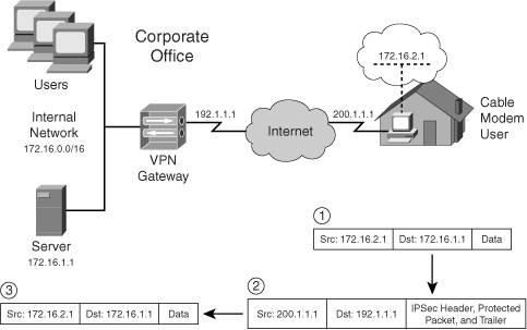
In Figure 3-2, the remote access client is assigned an internal IP address of 172.16.2.1 from the VPN gateway. When the client needs to send traffic to the internal server (172.16.1.1), it creates the packet shown in Step 1. The client, in Step 2, then protects the packet using IPsec (AH and/or ESP) and adds a second IP header to the packet, with the source address of 200.1.1.1 (assigned by the ISP) and a destination address of 192.1.1.1 (the VPN gateway). This packet is sent to the VPN gateway. In Step 3, the VPN gateway validates the IPsec packet and decrypts it, if necessary. Then the internally protected packet, now decrypted, is sent to the internal server. From the internal server's perspective, it appears that the remote access client is directly attached to the 172.16.0.0/16 network.
Client Connection Types
The assumption made in the last section was that the client was a user end-station, like a PC or laptop, when connecting to the corporate network; however, this doesn't necessarily have to be the case. For example, the remote access client could be a small router (Cisco 800, 900, and 1700 series), firewall (Cisco PIX 501 and 506E appliances), or hardware client (Cisco VPN 3002).
There are two types of Cisco remote access connections:
- Client mode
- Network or LAN extension mode
Client Mode
In client mode, the remote access client is assigned an internal IP address by the VPN gateway. However, this presents a problem for a hardware appliance that is the client. In this situation, devices behind the client need to access the tunnel to the corporate network. Cisco solves this problem by having the hardware appliance perform PAT on the inside devices' addresses to the assigned internal address before their traffic is sent across the tunnel. This process is shown in the top part of Figure 3-3, where the hardware appliance at the SOHO is a small-end router. The internal SOHO network segment is 192.168.1.0/24 and this traffic is translated to 172.16.2.1 by the router/client before being tunneled through the IPsec tunnel to the corporate site (172.16.2.1 is the client's internally assigned IP address).
Figure 3-3. Cisco Remote Access Connection Types
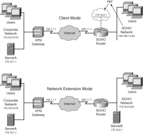
From the corporate site's perspective, the SOHO network actually looks like a single device: 172.16.2.1. Another advantage of client mode is that you can easily use a private address space at the SOHO. Actually, you could use the same address space at each SOHO using client mode, since the SOHO's traffic is PATed to a unique internal address assigned by the VPN gateway to the SOHO hardware appliance (the client).
When in client mode, you can either bring up the tunnel manually from the hardware client, or any user traffic behind the hardware client that needs to go to an external network will bring up the tunnel, even if the traffic is not destined to the central office. The tunnel must be brought up for the hardware client to learn the split tunneling policy, which dictates which traffic is tunneled and which traffic is sent to the ISP in clear-text.
LAN Extension Mode
One limitation of client mode is that the corporate office can't initiate connections to the SOHO devices because the SOHO hardware appliance is using PAT for address translation. To overcome this problem, Cisco developed network extension mode; Cisco sometimes refers to this as LAN extension mode.
Network extension mode simulates a site-to-site session, as shown in the bottom part of Figure 3-3; however, the session is still a remote access session and the SOHO device is treated as a client. Therefore, policies can still be applied to the group that the SOHO device (and the users behind it) belongs to.
In network extension mode, the VPN gateway doesn't assign an IP address to the client and the network segment at the SOHO must be unique throughout the network. The advantage of this approach is that if a device at the corporate site needs to initiate a connection to a SOHO device, the corporate device only would need to know the IP address of the specific SOHO device. For example, this would be necessary if you were using a voice over IP (VoIP) solution and had phones at both locations or needed to manage devices at the SOHOs. Also, unlike client mode, the hardware client would automatically bring up the remote access session to the VPN gateway, thereby allowing central office traffic to initiate connections to the SOHO devices.
Normally, the network number used at the SOHO in network extension mode is an extension of the address space used at the corporate site. In Figure 3-3, the corporation is using 172.16.0.0/16 and the SOHO is using a subnet of this: 172.16.2.0/24; however, you do not need to follow this process. Just remember that each SOHO site using network extension mode requires unique network numbers.
With Cisco, whether or not a remote access client can use client or network extension mode depends on the following two criteria:
- Only hardware appliances support both modes; software clients only support client mode.
- The use of network extension mode is a policy that sometimes must be enabled on a VPN gateway; otherwise, the hardware appliance might be restricted to using client modethis is true if the VPN gateway is a VPN 3000 concentrator.
Tip
I'm constantly asked which modeL2L or remote accessshould be used for connectivity from a SOHO or branch office when a hardware appliance is being used. I prefer to set the session up as a remote access session (instead of site-to-site) because I can easily centralize my remote access policies on the VPN gateway and push these down to the clients: hardware and software. Also, if the VPN device at the corporate office is a VPN 3000 concentrator, these typically support more remote access sessions than L2L sessions. When setting it up as a remote access session, if the corporate office needs to initiate connections to the SOHO devices, I'll use network extension mode; otherwise I'll use client mode.
Split Tunneling
As discussed in Chapter 1, split tunneling is the process of sending some traffic across a protected tunnel and some traffic in clear text. In remote access IPsec VPNs, the use of split tunneling is a policy defined on the VPN gateway and pushed to the client. In the Cisco implementation, split tunneling is, by default, disabled on the VPN gateway; therefore, once the IPsec tunnel comes up between the client and gateway, all traffic from the client is sent to the gateway across the protected connection. There is no option on the client to override this behavior. This gives you, the network administrator, control over what traffic should be protected.
In the Cisco implementation, two types of traffic are exceptions to this policy:
- ARP This must be allowed so that the client, if using an Ethernet interface, can learn the MAC addresses of devices so that it can communicate with directly connected devices, such as the ISP's access device.
- DHCP This must be allowed so that the client can obtain an address, typically from the ISP, and renew it once its lease expires.
Tip
Cisco recommends that if you use split tunneling, a firewall solution should be used to protect the client. If the client is a software client, a software firewall should be installed on the client to protect it against clear-text traffic from other sources, which could be attacks against the PC. For hardware appliances, I would either use a low-end PIX as a client, preferably, or a router with the IOS Firewall feature set installed; the 3002, as you will see in Chapter 14, "3002 Hardware Client," lacks the enhanced firewall capabilities of Cisco PIXs and routers.
Firewall Policies
Some remote access VPN implementations support the use of firewall policies. Firewall policies are defined on the VPN gateway and pushed to the client. The Cisco IPsec implementation supports two firewall policies:
- Are You There (AYT)
- Central Policy Protection or Push (CPP)
Both of these policies only apply to the Cisco VPN software client. With AYT, the policy is pushed down to the client and the client software periodically checks for the use of a firewall. If a firewall is not detected, the VPN Client software immediately tears down the IPsec session to the central site. This feature forces a remote access user to use a firewall to establish and maintain IPsec sessions to the VPN gateway.
One limitation of AYT is that it only detects the presence of a firewall. CPP allows you to push down specific filtering policies to the firewall product on the client. For example, you could push down a filter that allows the client to access specific destination addresses, but deny all other access. Both of these features are Cisco features and are not necessarily available in other vendors' IPsec remote access implementations. I'll discuss both of these features in more depth in Chapter 7, "Concentrator Remote Access Connections with IPsec."
Note
4.7 of the VPN 3000 concentrators support network admission control (NAC) in conjunction with the Cisco Trust Agent: this allows you to define other access policies, such as the use of anti-virus software on the client. Cisco routers also support NAC.
Split DNS
Another feature a VPN implementation may provide is the use of split DNS. Figure 3-4 illustrates the use of split DNS. In this network the DMZ devices are using private addresses (172.16.254.0/24); however, these devices are being represented with a static translation by the PIX with a global address from 192.1.1.0/24. When the SOHO client boots up and acquires an address from the ISP, it also acquires a DNS address (dynamically or manually). In this example, the DNS server address assigned to the client by the ISP is 200.1.1.254. Normally the client uses this address to resolve names to addresses; however, whenever the remote access client connects to the IPsec gateway, the gateway can also assign a DNS address to the client.
Figure 3-4. Split DNS Example
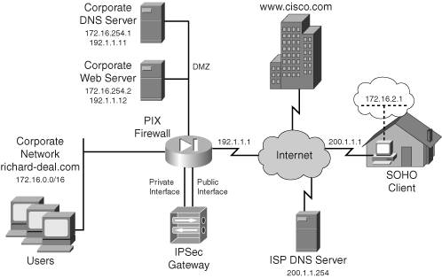
By default, split DNS is disabled; therefore, in Figure 3-4, if the SOHO client wanted to reach www.cisco.com, the DNS resolution would be forwarded across the IPsec tunnel to the DNS server (172.16.254.1) at the corporate office: the one assigned by the VPN gateway. However, this can cause problems. For example, let's assume the SOHO client wants to reach the DMZ web server. If the client wanted to reach a web server at the ISP, the DNS query would first go to the DMZ DNS server. The DMZ DNS server would forward this to a root DNS server, which, in turn, would forward this to the ISP DNS server to perform the resolution. In this situation, using the DMZ DNS server to perform all resolutions doesn't make sense.
Split DNS allows you, the IPsec gateway administrator, to control which DNS server the client uses. In this example, the corporate office's domain name is richard-deal.com. You could easily set up split DNS so that any resolution associated with richard-deal.com would be done by 172.16.254.1 and any other resolution would be done by the ISP's DNS server (200.1.1.254). To implement this, during IKE Mode Config, the IPsec gateway would send the list of DNS names to the client. If the client needed to do a DNS lookup for one of these names, it would use the DNS server assigned to it, during IKE Mode Config, by the IPsec gateway. Otherwise, the client would use the ISP's DNS server for name resolution.
Note
It is important to point out that in any DNS resolution done to the DNS server address, the VPN gateway supplied to the client is done across the secure data connection built in IKE Phase 2. In split DNS, if the client uses the ISP's DNS server, the DNS request is sent out in clear text directly to the ISP's server. This is basically a modified form of split tunneling. Likewise, split DNS won't work unless you also enable split tunneling, because resolutions for noncorporate devices must be sent clear-text to the ISP's DNS server. Also, split DNS is a Cisco feature that might not be available in other vendors' VPN implementations.
Reverse Route Injection
Remote access connectivity has routing issues. The top part of the network shown in Figure 3-5 illustrates this problem. In this network there are two VPN gateways for redundancy. The SOHO client has been configured and lists both VPN gateways, with VPN GatewayA the primary gateway and VPN GatewayB the backup gateway. The two routers, because they are in a different subnet (172.16.1.0/24) than the SOHO client (172.16.2.0/24), could have a static route pointing to VPN GatewayA; however, if this gateway were to go down and the client would connect to the backup gateway, VPN GatewayB, this would create a connectivity problem.
Figure 3-5. Remote Access and Routing Issues
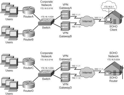
Another reachability issue can arise if the remote access client is a hardware appliance and is using network extension mode, like that shown in the bottom part of Figure 3-5. The problem in this situation is how the corporate office knows about the SOHO network, 172.16.3.0/24.
There are several ways of solving remote access routing problems, two of which are:
- Dynamic IP routing protocol
- Reverse Route Injection (RRI)
Using a dynamic routing protocol to solve the reachability issues that I previously mentioned presents problems. First, software clients might not support a routing protocol and therefore can't advertise their local routing information. Second, dynamic routing information that uses broadcasts and multicasts is not supported on IPsec connections. Only unicast traffic is supported. This can be circumvented by setting up a GRE tunnel between the remote access client and the VPN gateway device and sending routing traffic across this; but this assumes that these devices support GRE tunnels. Only Cisco routers and certain implementations of Unix support GRE, so this could pose a problem and might not be a viable solution.
The Cisco RRI provides the best approach for remote access clients. RRI is a Cisco-proprietary enhancement for IPsec. At the end of ISAKMP/IKE Phase 1, the remote access client does one of the following:
- If in client mode, the client is assigned an internal address by the VPN gateway; the VPN gateway will add this as a static route to its local routing table.
- If in network extension mode, the client sends the network number of its inside interface to the VPN gateway via an ISAKMP/IKE Phase 1 message.
On the VPN gateway side, the client or network route is placed in the local routing table as a static route and can be redistributed via a dynamic routing protocol to devices on the corporate network. This solution provides scalability because it doesn't matter which VPN gateway the client connects to, the routing information is updated dynamically and allows internal devices to learn which VPN gateway a remote access software or hardware client is connected to.
Note
One limitation of RRI is that only a single route can be advertised to the VPN gateway during ISAKMP/IKE Phase 1 for hardware clients using network extension mode. If the remote access hardware client had more than one network segment behind it, RRI won't solve this problem. In this situation, you would need to use a site-to-site implementation and use a static or dynamic routing process.
Part I: VPNs
Overview of VPNs
- Overview of VPNs
- Traffic Issues
- VPN Definition
- VPN Components
- VPN Designs
- VPN Implementations
- VPNs: Choosing a Solution
- Summary
VPN Technologies
IPsec
- IPsec
- IPsec Standards
- ISAKMP/IKE Phase 1
- ISAKMP/IKE Phase 2
- IPsec Traffic and Networks
- Summary
PPTP and L2TP
SSL VPNs
Part II: Concentrators
Concentrator Product Information
- Concentrator Product Information
- Concentrator Models
- Concentrator Modules
- Concentrator Features
- Introduction to Accessing a Concentrator
- Summary
Concentrator Remote Access Connections with IPsec
- Concentrator Remote Access Connections with IPsec
- Controlling Remote Access Sessions to the Concentrator
- IPsec Remote Access
- Network Access Control (NAC) for IPsec and L2TP/IPsec Users
- Summary
Concentrator Remote Access Connections with PPTP, L2TP, and WebVPN
- Concentrator Remote Access Connections with PPTP, L2TP, and WebVPN
- PPTP and L2TP Remote Access
- WebVPN Remote Access
- Summary
Concentrator Site-to-Site Connections
- Concentrator Site-to-Site Connections
- L2L Connectivity Example
- ISAKMP/IKE Phase 1 Preparation
- Adding Site-to-Site Connections
- Address Translation and L2L Sessions
- Summary
Concentrator Management
- Concentrator Management
- Bandwidth Management
- Routing on the Concentrator
- Chassis Redundancy
- Administration Screens
- Summary
Verifying and Troubleshooting Concentrator Connections
- Verifying and Troubleshooting Concentrator Connections
- Concentrator Tools
- Troubleshooting Problems
- Summary
Part III: Clients
Cisco VPN Software Client
- Cisco VPN Software Client
- Cisco VPN Client Overview
- Cisco VPN Client Interface
- IPsec Connections
- VPN Client GUI Options
- VPN Client Software Updates
- VPN Client Troubleshooting
- Summary
Windows Software Client
- Windows Software Client
- Windows Client
- Configuring the Windows VPN Client
- Configuring the VPN 3000 Concentrator
- Microsoft Client Connections
- Troubleshooting VPN Connections
- Summary
3002 Hardware Client
- 3002 Hardware Client
- Overview of the 3002 Hardware Client
- Initial Access to the 3002
- Authentication and Connection Options
- Connection Modes
- Administrative Tasks
- Summary
Part IV: IOS Routers
Router Product Information
Router ISAKMP/IKE Phase 1 Connectivity
- Router ISAKMP/IKE Phase 1 Connectivity
- IPsec Preparation
- ISAKMP/IKE Phase 1 Policies
- ISAKMP/IKE Phase 1 Device Authentication
- Monitoring and Managing Management Connections
- Routers as Certificate Authorities
- Summary
Router Site-to-Site Connections
- Router Site-to-Site Connections
- ISAKMP/IKE Phase 2 Configuration
- Viewing and Managing Connections
- Issues with Site-to-Site Connections
- Summary
Router Remote Access Connections
- Router Remote Access Connections
- Easy VPN Server
- Easy VPN Remote
- IPsec Remote Access and L2L Sessions on the Same Router
- WebVPN
- Summary
Troubleshooting Router Connections
- Troubleshooting Router Connections
- ISAKMP/IKE Phase 1 Connections
- ISAKMP/IKE Phase 2 Connections
- New IPsec Troubleshooting Features
- Fragmentation Problems
- Summary
Part V: PIX Firewalls
PIX and ASA Product Information
- PIX and ASA Product Information
- PIX Deployment Scenarios
- PIX and ASA Feature and Product Overview
- Summary
PIX and ASA Site-to-Site Connections
- PIX and ASA Site-to-Site Connections
- ISAKMP/IKE Phase 1 Management Connection
- ISAKMP/IKE Phase 2 Data Connections
- L2L Connection Examples
- Summary
PIX and ASA Remote Access Connections
- PIX and ASA Remote Access Connections
- Easy VPN Server Support for 6.x
- Easy VPN Remote Support for 6.x
- Easy VPN Server Support for 7.0
- Summary
Troubleshooting PIX and ASA Connections
- Troubleshooting PIX and ASA Connections
- ISAKMP/IKE Phase 1 Connections
- ISAKMP/IKE Phase 2 Connections
- Summary
Part VI: Case Study
Case Study
Index
EAN: 2147483647
Pages: 178
