Adding Site-to-Site Connections
Once you have set up your IKE policies for your management connection, you are ready to create your L2L session. To add (or modify) an L2L session, go to Configuration > Tunneling and Security > IPsec > LAN-to-LAN. The resulting screen lists the existing L2L connections.
Note
Chapter 6, "Concentrator Product Information," discussed the use of Quick Configuration to put a minimal configuration on your concentrator. This method only allows you to set up remote access connectivity. Before you can add an L2L session, you must configure the concentrator's public interface by, at minimum, assigning an IP address to it. This can be done using Quick Configuration or going to Configuration > Interfaces.
To assist you with building and maintaining L2L sessions, the following subsections cover these topics:
- Adding L2L Sessions
- Completing L2L Sessions
- Modifying L2L Sessions
Adding L2L Sessions
The following subsections cover these topics:
- Basic L2L Configuration Parameters
- Peer Connectivity
- Device Authentication Information
- Connection Policies
- Routing Options
- Local and Remote Networks
Basic L2L Configuration Parameters
To add a new session, click the Add button, where you'll be taken to the screen shown in Figures 9-3, 9-4, 9-5, and 9-6 (I've broken this screen into multiple figures). The first parameter at the top of the screen in Figure 9-3 is the Enable parameterclicking this check box enables this specific L2L session. This option allows you to disable a session without having to delete the session, which might be useful when you are trying to troubleshoot a problem.
Figure 9-3. L2L Screen: Part 1
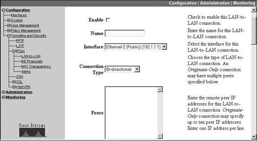
Figure 9-4. L2L Screen: Part 2
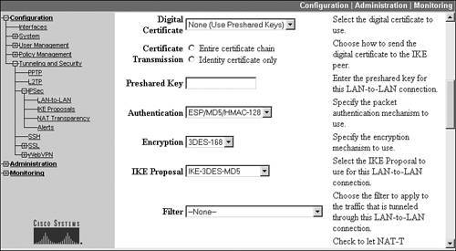
Figure 9-5. L2L Screen: Part 3
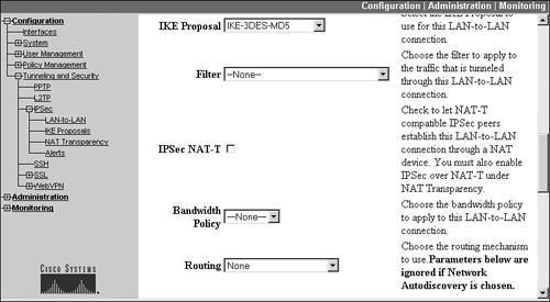
Figure 9-6. L2L Screen: Part 4
The Name parameter allows you to give a descriptive name (up to 32 characters) for the L2L session. Because this name is used for other related items the concentrator creates for the L2L session, such as a filter and data SA, I recommend that you keep the name of the session short (when you're done adding the connection, this name appears on the Configuration > Tunneling and Security > IPsec > LAN-to-LAN screen).
The Interface parameter specifies which interface the concentrator should use to reach the remote site. This defaults to "Public," which is probably the one you're using for the IPsec tunnel. Also, once you add an L2L session, you cannot change the interface to use for the session unless you delete the L2L session and re-add it with the correct interface.
Peer Connectivity
The Connection Type parameter specifies how the L2L connection will be built. There are three options:
- "Bidirectional" This option should be chosen if either this concentrator or the remote peer will initiate the L2L session; it's commonly used when no redundancy is being used between the two sites.
- "Answer-only" This option is used when you don't want this peer to initiate the session, but want the remote peer to do this; it's commonly chosen when redundancy is used between two sites. For example, in Figure 9-1, this would be configured on the two concentrators (ConcentratorA and ConcentratorB) at the corporate office. This is necessary to ensure that both of these concentrators don't set up two connections to a single remote site.
- "Originate-only" This option is used when you want this L2L peer to initiate a session to an "Answer-only" peer; it's commonly chosen when redundancy is used between two sites. For example, in Figure 9-1, this option would be configured at the three remote sites: Orlando, Tampa, and Miami.
Note
I'll talk more about redundancy for L2L sessions later in the chapter in the "Routing Options" section.
The Peer text box allows you to enter multiple peer addresses (up to ten). For example, in Figure 9-1, the Orlando concentrator would specify the two concentrator addresses at the corporate site, 200.1.1.1 for ConcentratorA and 200.1.1.2 for ConcentratorB, for redundancy. The order in which you enter the addresses is important: put the primary L2L peer's address first and the backup L2L peer second. Doing so will cause the concentrator to contact the L2L peer at the top of the list first.
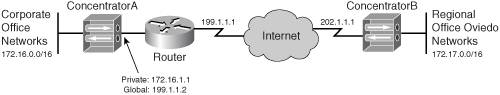
Also, if the remote peer is using a private address on its public interface, you'll need to configure the global NAT address associated with the private (local) address; in other words, if the remote peer has a private address, you need to specify the externally reachable or visible address that represents this peer (which will be translated to the private address). For example, in Figure 9-7, ConcentratorA has a private address (172.16.1.1) assigned to its public interface. A static NAT definition exists on the router that translates this to the global address of 192.1.1.2. Therefore, ConcentratorB needs to configure the global address as the peer address when establishing an L2L connection to ConcentratorA.
Figure 9-7. L2L Connection and Private Addressing
Note
In the example in Figure 9-1, each of the remote site concentrators will configure the same two peer addresses: 200.1.1.1 and 200.1.1.2; however, if you add them in this order on the remote concentrators, ConcentratorA will handle all three L2L sessions; therefore, you'll probably want to look at the traffic sent between the three remote sites and the corporate office, and have the L2L session of the remote site that sends the most traffic terminated on one corporate concentrator, and the other two remote sites' L2L sessions terminated on the second corporate concentrator. For example, if the Orlando office generated the most amount of traffic, its primary peer at the corporate office would be 2001.1.1.1, and its backup peer would be 200.1.1.2. However, on the other two remote office concentrators, I would configure the primary peer at the corporate office as 200.1.1.2 and the backup peer as 200.1.1.1. Given this configuration, I've split the L2L sessions between the two concentrators at the corporate site; plus, if either concentrator fails at the corporate site, the remote offices already have a backup peer configured. I'll talk more about redundancy for L2L sessions later in the chapter in the "Routing Options" section.
Device Authentication Information
The next two parameters, Digital Certificate and Certificate Transmission, are shown in Figure 9-4 (this is still the same screen). These parameters are only applicable if the two L2L peers will be using certificates for device authentication during ISAKMP/IKE Phase 1. The Digital Certificate parameter is a drop-down selector that allows you to choose your authentication option (assuming this matches what you've chosen in your IKE proposal). The default value for this parameter is "None (Use Preshared Keys)." If you are going to use certificates for device authentication, you'll need to use the drop-down selector to choose the actual identity certificate to use for this L2L session.
The Certificate Transmission parameter allows you to specify what certificate information is sent to the remote peer during device authentication. Your two options are:
- "Identity certificate only" Send the remote L2L peer only this concentrator's identity certificate specified in the Digital Certificate parameter.
- "Entire certificate chain" Send the remote L2L peer the concentrator's identity certificate specified in the Digital Certificate parameter, and the corresponding root and subordinate CA certificates (if you're using a hierarchical PKI implementation).
If you're using pre-shared keys for device authentication during ISAKMP/IKE Phase 1, you'll need to enter the pre-shared key value in the Preshared Key text box. The key can be from 432 alphanumeric characters. Whatever key you configure on this concentrator must be configured exactly the same on the remote L2L peer.
The Authentication drop-down selector allows you to choose the HMAC function that should be used for the ESP data connections. If you recall from Chapter 2, "VPN Technologies," HMAC functions are used to verify a packet's integrity (the packet hasn't been tampered with) and to authenticate the origin of the packet. Your options for this parameter are "None," "ESP/MD5/HMAC-128," and "ESP/SHA/HMAC-160."
Note
Please note that the concentrator doesn't support AH for L2L sessions, whereas other VPN gateway products, like Cisco routers, do.
The other ESP parameter you can configure is the Encryption algorithm, which specifies the encryption algorithm to use for the data connections. Your options are "Null" (no encryption), "DES-56," "3DES-168," "AES-128," "AES-192," and "AES-256." The configuration of these two parameters is used to build a data transform set that will be used during ISAKMP/ IKE Phase 2. Remember that what you configure on the local concentrator must match the data transform set on the remote L2L peer.
Connection Policies
The IKE Proposal drop-down selector allows you to choose the IKE policy that will be used to build and protect the ISAKMP/IKE Phase 1 management connection to the remote L2L peer. This is shown in Figure 9-5. The policies shown here are only the ones in the Active Proposals column on the Configuration > Tunneling and Security > IPsec > IKE Proposals screen. Remember that this management transform must match the one that is used on the remote L2L peer. I discussed the configuration of IKE policies for L2L connections earlier in the chapter in the "ISAKMP/IKE Phase 1 Preparation" section.
The Filter drop-down selector allows you to select an access control list (ACL) filter to filter traffic coming across the tunnel from the remote L2L peer. I discussed the creation of filters in Chapter 7, "Concentrator Remote Access Connections with IPsec." To create a filter, you must first create rules that define filtering actions; you then associate the rules to a filter.
If you recall from Chapter 3, "IPsec," and Chapter 7, "Concentrator Remote Access Connections with IPsec," NAT-T allows ESP to be tunneled through an address translation device performing PAT; the ESP packet is encapsulated in a UDP segment with a destination port number of 4,500, and then an outer IP header is added. Normally this is used to solve address translation issues with remote access clients accessing a VPN gateway. However, you might run into a situation where, for a small site, the ISP assigns a single public IP address to the small site, like that shown in Figure 9-8.
Figure 9-8. L2L and NAT-T

In this figure, the ISP assigned a single IP address to the Sanford office: 211.1.1.1, which is assigned to the external interface of the perimeter router. This presents a problem for the site-to-site session between the two concentratorsConcentratorA and ConcentratorBbecause the perimeter router at the Sanford site will have to perform PAT with this address to allow internal TCP and UDP traffic to access the Internet. For example, if ConcentratorA were to send traffic to 211.1.1.1, the perimeter router in Sanford would attempt to process the traffic itself.
To solve this problem of the Corporate office concentrator (ConcentratorA) accessing the Sanford concentrator (ConcentratorB), you would need to configure two static PAT translations (port address redirection, or PAR) on the Sanford perimeter router:
- One PAR rule for the ISAKMP/IKE Phase 1 management connection (UDP 500), where this traffic is redirected to 172.20.1.1
- One PAR rule for the ESP data connections
The problem with the second PAR rule on the perimeter router is that ESP is a Layer-3 protocol and PAR needs a Layer-4 protocol such as UDP or TCP. In this situation, you can use NAT-T for the ESP data connections. Recall from Chapter 7 that NAT-T uses a port number of UDP 4,500. Therefore, the second PAR rule would redirect any UDP port 4,500 traffic sent to 211.1.1.1 to 172.20.1.1. For this to work, you would need to do the following on both concentrators:
|
1. |
Enable NAT-T in the Configuration > Tunneling and Security > IPsec > NAT Transparency screen. |
|
2. |
Select the check box for the L2L connection in the Configuration > Tunneling and Security > IPsec > LAN-to-LAN add/modify screen. |
Note
When you have enabled and are using NAT-T, the following restrictions apply:
- Only one L2L session can use NAT-T.
- Only one Microsoft L2TP/IPsec client can use NAT-T and multiple IPsec clients can use NAT-T.
- Either one L2L session can use NAT-T or multiple IPsec remote access clients can use NAT-T.
Because of these restrictions, NAT-T is typically reserved for remote access use.
Also, please note that Microsoft was to provide a patch in July 2005 to remove the restriction of only one Microsoft L2TP/IPsec client using NAT-T.
Bandwidth policies allow you to limit traffic rates for sessions. There are two types of bandwidth policies: policing and reservation. Bandwidth policies can be applied to an interface, a group (remote access users), or an L2L session (which is treated as a group by the concentrator software). The Bandwidth Policy drop-down selector allows you to apply a bandwidth policy to the L2L session, ensuring that the L2L session receives enough bandwidth or doesn't use up all available bandwidth. I'll discuss the use and configuration of bandwidth management in more depth in Chapter 10, "Concentrator Management."
Routing Options
L2L connections support three routing options with the Routing parameter drop-down selector:
- "None"
- "Reverse Route Injection"
- "Network Autodiscovery"
The following sections will discuss the usage of these parameters.
None: Static Routing
If you choose "None" for the Routing parameter, then by default, the concentrator doesn't use any routing functions either to learn about the remote L2L peer's networks or to propagate these to internal devices. Figure 9-9 illustrates an example.
Figure 9-9. L2L Connections and Routing
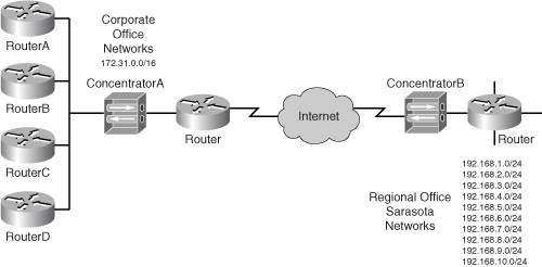
In this example, a regional office, Sarasota, has ten networks that need to reach the corporate office and the corporate office's B-class network needs to reach all networks at the Sarasota office. When you choose "None" for your Routing parameter on your concentrator, the corporate office will, by default, know nothing about the 192.168.x.0 networks at Sarasota.
In this situation, you will need to statically configure these networks below in the Remote Network section (see Figure 9-6) with a network list (I'll discuss the configuration of the network list later in the "Local and Remote Networks" section of the chapter.)
By configuring the networks locally on the corporate office concentrator, the concentrator now knows about the ten networks at Sarasota; however, using the "None" option doesn't place them in the routing and table and therefore ConcentratorA at the corporate office doesn't advertise them to the local routers and local devices. To solve this problem, you would need to configure static routes on the internal routers (RouterA, RouterB, RouterC, and RouterD) and point them to the concentrator. If there are more routers behind the four listed in Figure 9-9, you would need to redistribute the static routes into the local routing protocol to propagate the 192.168.x.0 networks throughout the corporate network.
Note
Because the "None"Routing option doesn't propagate L2L routing information, typically it is used in a spoke configuration where the concentrator doesn't need to advertise routing information, or minimal configuration is needed on routers to configure and propagate static routing information statically.
Reverse Route Injection
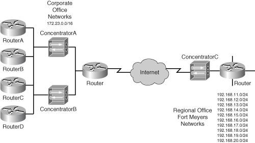
The "None" Routing option also has another problem, as illustrated in Figure 9-10. In this example, the corporate office has two concentrators for redundancy: ConcentratorA and ConcentratorB. ConcentratorC at Fort Myers is configured to use ConcentratorA as the primary concentrator and ConcentratorB as the backup. Given this situation, if you were to configure static routes at the corporate office routers to point to ConcentratorA, and this concentrator failed, then even when ConcentratorC rebuilt the connection to the backup concentrator at the corporate office, ConcentratorB, the corporate office devices still would be forwarding their traffic to the downed concentrator, ConcentratorA.
Figure 9-10. L2L Connections, Routing, and Redundancy
There are three possible solutions to this problem:
- NAD on the concentrators
- VRRP on the concentrators
- RRI on the concentrators
I'll discuss NAD in the next section. VRRP provides default gateway redundancy. If you choose the VRRP option to solve the problem, you must enable VRRP on both concentrators. When you do this, the internal routers would point to the virtual address to reach the tunnel, and whichever concentrator would be the master would process traffic sent to the remote site.
The main problem with VRRP is that you can't use it with the Virtual Cluster Agent (VCA) feature, which allows load balancing of remote access connections. Therefore it is typically not used when you are using the concentrator for both L2L and remote access. I'll discuss VRRP and its configuration in more depth in Chapter 10, "Concentrator Management."
Reverse Route Injection (RRI) is the second way to solve the problem in Figure 9-10. To enable RRI, set the Routing parameter to "Reverse Route Injection." RRI can be used when you need redundancy or load balancing for L2L or remote access sessions. In other words, for Figure 9-10, you might not know which concentrator ConcentratorC will connect to at the corporate site (nor, for that matter, which corporate site concentrator remote access clients will connect to). RRI can be used to dynamically share the concentrator's networks for IPsec sessions with devices behind it using a dynamic routing protocol. For example, in Figure 9-10, if ConcentratorC connects to ConcentratorA, ConcentratorC will advertise the 192.168.x.0 networks to the internal corporate office routers using a dynamic routing protocol. RRI supports both RIPv1/2 and OSPF.
If you had chosen "Reverse Route Injection" for the Routing parameter on the concentrator's L2L configuration screen in Figure 9-5, you would need to configure a few additional items on the concentrator. First, the L2L concentrators at both ends of the connection know nothing about the routes at the remote side. Therefore, you must manually configure these in the Local Network and Remote Network sections in Figure 9-6 of each concentrator. In the example in Figure 9-10, for ConcentratorC you would have to define 172.23.0.0/16 to be associated with the corporate site. On both ConcentratorA and ConcentratorB, you would need to configure the 192.168.x.0 networks to be associated with ConcentratorC.
This configuration brings up an interesting problem: if you configure the 192.168.x.0 routes on both ConcentratorA and ConcentratorB, these concentrators won't advertise the routes until something brings the tunnel up. Of course, someone at the Fort Myers office could do this. At the Fort Myers office, a default or specific route (172.23.0.0/16) would have to be set up and advertised to the Fort Myers routers so that internal users could reach the concentrator to reach the corporate office. When the tunnel would come up to either of the two corporate concentrators, RRI would allow them to advertise the 192.168.x.0 networks to the corporate users. Thus, the corporate users would be able to access any of the networks at the Fort Myers office.
However, what if someone at the corporate office was first in needing to send traffic to the Fort Myers office? How would they know which concentrator to go to in order to set up the session, because the concentrators aren't advertising the routes via RRI until the tunnel comes up?It's a catch22 situation. One option is to force the concentrators to advertise the routes. This feature is called hold-down routes. Hold-down routes force the concentrator to advertise the RRI routes whether or not the tunnel is up to the remote peer.
To set up hold-down routes, you would go to Configuration > Services > IP Routing > Reverse Route Injection, as shown in Figure 9-11.
Figure 9-11. RRI and Hold-Down Routes
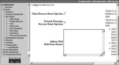
The Address Pool Hold-Down Routes text box allows you to manually enter routes you always want the concentrator to advertisewhether or not they are reachable. With RRI, you would manually enter the networks in the Remote Network that you entered in Figure 9-6. Each route is placed on a separate line and the syntax is:
x.x.x.x/y.y.y.y
x.x.x.x is the network and y.y.y.y is a wildcard mask, not a subnet mask. So for the example of ConcentratorA and ConcentratorB, you would enter 192.168.11.0/0.0.0.255 for the first network, and so on, for the rest of the networks. When done, click the Apply button at the bottom of the screen.
Once you do enter your hold-down router, RRI will cause the concentrator to always advertise the routes out of its private interface. At first this seems to fix the problem because now the corporate devices know that the two concentrators can reach the Fort Myers networks. However, this solution won't work; both concentrators are sharing the same routes, but which one should the corporate office useConcentratorA or ConcentratorB if both are advertising the routes? What if your routers are set up for load balancing and split the traffic between the two concentrators? This is true even if you would try to use VRRP, because both corporate office concentrators (master and backup) would still be advertising the same routing information.
Given this example, RRI is not a good solution to use when there are redundant concentrators: it's a good solution when there is a single concentrator at one side and there is only one possible path to reach the remote site (via the concentrator). For example, RRI with hold-down routes would be a better solution for the network in Figure 9-8. In this example, there are only two concentrators that can provide connectivity. By using RRI with hold-down routes, both concentrators can advertise the remote networks you have defined locally in the L2L screen instead of configuring static routes on your internal routers.
If you are going to use RRI in single concentrator locations, you must also enable a routing protocol for your private interface. For OSPF, you would need to enable it and assign a process ID to the routing process on the Configuration > System > IP Routing > OSPF screen, and then for either OSPF or RIP, you would need to enable the specific routing protocol on your concentrator's private interface. I discuss how you set up routing in more depth in Chapter 10, "Concentrator Management." I'll also discuss RRI in more depth in Chapter 14, "3002 Hardware Client," where I cover its use for remote access connections.
Network Autodiscovery (NAD)
As you saw in the last section, RRI doesn't work well (or at all) when you have redundant concentrators at a site. In such a situation, NAD is the solution of choice on the concentrators. With NAD, you do not need to manually define the local and remote subnets (statically or with network lists) that will traverse the L2L tunnel; instead, you have NAD do this dynamically.
For NAD to function, RIP must be enabled on the concentrator's private interface in the inbound and outbound direction. Once this is enabled, the concentrator will take RIP updates learned from the private interface, encrypt them, and send them across the tunnel to the remote concentrator. If a tunnel is not currently established between the two concentrators, one of the concentrators will automatically bring it up. This is different from the "None" and "Reverse Route Injection" routing options where user traffic must bring up the tunnel.
Note
NAD only supports RIP as a dynamic routing protocol; OSPF is not supported. For more information about setting up RIP on the concentrator, see Chapter 10, "Concentrator Management." Also, only concentrators support NAD, so you can't use a router or PIX as the remote end of the L2L session.
I'll look at two different situations where NAD can be useful. First I'll use Figure 9-9 as my example network. In this example, the Sarasota office has many 192.168.x.0 C-class networks that need to be reached at the corporate office. On both concentrators in the L2L configuration, you would set the Routing parameter to "Network Autodiscovery" (this parameter can be seen previously in Figure 9-5). With both concentrators, you don't need to specify the local and remote networks in the Local Network and Remote Network sections in Figure 9-6. Just leave these blank. Remember that NAD will bring up the tunnel and share the routes on the two sides via RIP automatically. As you can see, this was a fairly simple process to configure.
Let's look at a more complicated design like that shown previously in Figure 9-10, where the corporate office has redundant concentrators. At the corporate office, you don't want both concentrators establishing an L2L session to the Fort Myers concentrator. Therefore, you'll set the Connection Type parameter on each corporate concentrator to "Answer-Only" and the Fort Myers concentrator to "Originate-Only." This will cause Fort Myers to initiate the session, ensuring that there is only one L2L session between the two sites.
After you have configured the connection types properly, you'll need to enable NAD on the three concentrators by setting the Routing parameter to "Network Autodiscovery." Then, you will need to enable RIP in both the inbound and outbound directions of your concentrators' private interfaces. If your corporate office routers are not running RIP, then you'll need to enable it on the routers connected to ConcentratorA and ConcentratorB and redistribute the NAD RIP routes into the local routing protocol, like OSPF or EIGRP. If the local routing protocol is not RIP, you'll need to redistribute the local routes into RIP so that one of the two corporate office concentrators can advertise these to the Fort Myers concentrator. If the local routing protocol is OSPF, you can just enable OSPF on the concentrator and advertise the router OSPF routes directly to the corporate concentrator (via RIP). The corporate concentrator with the L2L to Fort Myers can then use NAD to advertise these as RIP routes to ConcentratorC.
At the Fort Myers office, you would list two remote peer addresses for the endpoints of the L2L connection, the address of each corporate office concentrator's public interface. Remember that if these are private addresses, and the corporate router is performing NAT, you would need to configure a static NAT translation on the perimeter router and then use the global (public) addresses in the configuration on ConcentratorC. You also would need to enable NAD for the Routing parameter. Last, on ConcentratorC, you would need to have it initiate the connection by setting the Connection Type to "Originate-Only," which would cause Fort Myers' concentrator to initiate the connection to the primary concentrator at the corporate site, ensuring that there would be only one connection between the two sites.
Caution
If you decide to use NAD, remember that both sides must be 3000 series concentrators: NAD won't work with other products. Also, NAD shares the entire routing table of each peer with the remote peer. If you don't want certain networks to be accessed by a remote peer, then you would need to configure a filter on your concentrator and apply it to the L2L session to block the unwanted traffic. (I discussed the use of filters for L2L connections earlier in the "Connection Policies" section.) Last, the concentrators must use RIP to advertise the routes to internal devices, which might present an issue if you are running a different routing protocol, like OSPF. In this situation you would have to set up redistribution to redistribute the concentrator RIP routes into the router's local routing process (like OSPF). This cannot be done on a concentrator, but can be done easily on an internal Cisco router connected to the concentrator.
Local and Remote Networks
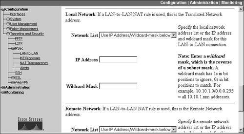
The Local Networks and Remote Networks section of the screen in Figure 9-6 needs to be configured if you have chosen "None" or "Reverse Route Injection" for the Routing parameter. These two sections allow you to manually define the network or networks located at each side of the two L2L peers. This configuration isn't necessary if you are using NAD, because NAD shares the routing information between the two peers dynamically.
The Local Networks section allows you to define the local networks that you want to protect when traffic is sent to the networks listed in the Remote Networks section. If you don't list a particular network in either section, traffic to or from that network is not protected by IPsec. In both sections, you can enter:
- A single network using the IP Address and Wildcard Mask fields
- A range of contiguous networks using the IP Address and Wildcard Mask fields
- A single network, a range of contiguous networks, or a list of networks using the Network List drop-down selector.
If you choose the last option, you must define the network list first (I discussed this process in Chapter 7, "Concentrator Remote Access Connections with IPsec," where network lists are configured by going to Configuration > Policy Management > Traffic Management > Network Lists). In most cases, if I need to list more than one network, I typically use the network list option.
In addition, the network configuration that you create on one concentrator must be mirrored on the remote L2L peer. I'll use Figure 9-8 to illustrate this. For ConcentratorA, the local network would be 172.20.0.0 0.0.255.255 and the remote network would be 172.21.0.0 0.0.255.255. On ConcentratorB, the local network and remote networks would be reversed (mirrored); the local network would be 172.21.0.0 0.0.255.255 and the remote network would be 172.20.0.0 0.0.255.255. Please note that because there is just a single network at each side, you don't have to use network lists, but could configure this easily using the IP Address and Wildcard Mask fields.
Note
If you are using L2L NAT, discussed later in the "Address Translation and L2L Sessions," section you would enter the global translated network in the Remote Network section.
Completing L2L Sessions
Depending on whether you are adding or modifying an L2L session, when you are finished, you'll see one of two screens. The next section discusses these two possible alternatives. Plus, when you add a new session, the concentrator automatically creates certain components it uses to implement the L2L session; the following section will cover these components.
If you were modifying your L2L session, click the Apply button at the bottom of the screen: you'll be taken back to the Configuration > Tunneling and Security > IPsec > LAN-to-LAN screen, where you'll see the list of L2L connections configured on the concentrator.
Caution
As soon as you make and apply your changes to an existing L2L session, and an IPsec tunnel is currently established to the remote L2L peer, the existing tunnel is terminated and a new one is built. This could cause a brief disruption in your user traffic.
However, if you were adding a new L2L session instead of modifying an existing one, click the Add button at the bottom of the screen. When you do this, the session is added and you are taken to the screen shown in Figure 9-12.
Figure 9-12. L2L Completion Screen
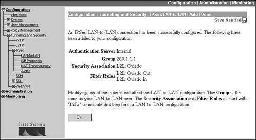
You'll notice some interesting items on this screen. First, the authentication of the remote L2L peer is done by the concentrator itself: the Authentication Server is set to "Internal." Also, three components for the L2L session are created automatically by the concentrator:
- A group for the L2L session (in the example in Figure 9-12, it is called "200.1.1.1," which is based on the IP address of the remote L2L peer configured on the screen shown in Figure 9-3)
- A security association for the L2L connection that defines how the two unidirectional data connections in ISAKMP/IKE Phase 2 will be protected (basically a transform set which is called "L2L: name," where the name is derived from the Name parameter in the L2L configuration in Figure 9-3)
- Two filtering rules that allow IPsec traffic between the remote L2L peer and this concentrator (the filters are named "L2L: name," where the name is derived from the Name parameter in the L2L configuration in Figure 9-3); these rules are automatically added to the filter on which the L2L connection is terminated (typically the public interface) and allows the IPsec traffic between the two peers
The following section will discuss these three items in more depth.
Click the OK button to return to the Configuration > Tunneling and Security > IPsec > LAN-to-LAN screen, where you'll see the list of L2L connections configured on the concentrator (including your new session).
Modifying L2L Sessions
As I mentioned in the last section, whenever you add an L2L session, the concentrator automatically creates the L2L session, a group for the L2L session, two filtering rules for the L2L session, and an IPsec SA for the L2L session. Likewise, any time you modify an L2L session, these components are automatically updated by the concentrator.
If you want to see the components the concentrator created, you can go to the following concentrator locations:
- The new group: Configuration > User Management > Groups
- The new IPsec SA: Configuration > Policy Management > Traffic Management > SAs
- The two new filtering rules: Configuration > Policy Management > Traffic Management > Rules
If you go to any of these screens, you'll see the parameters you specified from the Configuration > Tunneling and Security > IPsec > LAN-to-LAN Add/Modify screen or for other parameters that don't apply to L2L session, the default parameters for the screen(s).
Please note that you cannot delete the filtering rules, the SAs, or the group the concentrator added for the L2L session; however, you can modify the parameters for these three items in their respective screens. Also, if you delete the L2L session from the Configuration > Tunneling and Security > IPsec > LAN-to-LAN Add/Modify screen, the extra components added for the L2L connectionfilters, group, and SAare automatically deleted by the concentrator.
Tip
I highly recommend that you use only the Configuration > Tunneling and Security > IPsec > LAN-to-LAN Add/Modify screen when modifying an L2L connection, because modifying any of the other components from their respective screens could cause undesirable results. However, there are certain parameters available on screens for the groups and SAs that are not available on the LAN-to-LAN screen, such as the use of perfect forward secrecy (PFS) on the SA screen to use DH to share the encryption and hash keys for the data connections instead of using the existing management connection.
Part I: VPNs
Overview of VPNs
- Overview of VPNs
- Traffic Issues
- VPN Definition
- VPN Components
- VPN Designs
- VPN Implementations
- VPNs: Choosing a Solution
- Summary
VPN Technologies
IPsec
PPTP and L2TP
SSL VPNs
Part II: Concentrators
Concentrator Product Information
- Concentrator Product Information
- Concentrator Models
- Concentrator Modules
- Concentrator Features
- Introduction to Accessing a Concentrator
- Summary
Concentrator Remote Access Connections with IPsec
- Concentrator Remote Access Connections with IPsec
- Controlling Remote Access Sessions to the Concentrator
- IPsec Remote Access
- Network Access Control (NAC) for IPsec and L2TP/IPsec Users
- Summary
Concentrator Remote Access Connections with PPTP, L2TP, and WebVPN
- Concentrator Remote Access Connections with PPTP, L2TP, and WebVPN
- PPTP and L2TP Remote Access
- WebVPN Remote Access
- Summary
Concentrator Site-to-Site Connections
- Concentrator Site-to-Site Connections
- L2L Connectivity Example
- ISAKMP/IKE Phase 1 Preparation
- Adding Site-to-Site Connections
- Address Translation and L2L Sessions
- Summary
Concentrator Management
- Concentrator Management
- Bandwidth Management
- Routing on the Concentrator
- Chassis Redundancy
- Administration Screens
- Summary
Verifying and Troubleshooting Concentrator Connections
- Verifying and Troubleshooting Concentrator Connections
- Concentrator Tools
- Troubleshooting Problems
- Summary
Part III: Clients
Cisco VPN Software Client
- Cisco VPN Software Client
- Cisco VPN Client Overview
- Cisco VPN Client Interface
- IPsec Connections
- VPN Client GUI Options
- VPN Client Software Updates
- VPN Client Troubleshooting
- Summary
Windows Software Client
- Windows Software Client
- Windows Client
- Configuring the Windows VPN Client
- Configuring the VPN 3000 Concentrator
- Microsoft Client Connections
- Troubleshooting VPN Connections
- Summary
3002 Hardware Client
- 3002 Hardware Client
- Overview of the 3002 Hardware Client
- Initial Access to the 3002
- Authentication and Connection Options
- Connection Modes
- Administrative Tasks
- Summary
Part IV: IOS Routers
Router Product Information
Router ISAKMP/IKE Phase 1 Connectivity
- Router ISAKMP/IKE Phase 1 Connectivity
- IPsec Preparation
- ISAKMP/IKE Phase 1 Policies
- ISAKMP/IKE Phase 1 Device Authentication
- Monitoring and Managing Management Connections
- Routers as Certificate Authorities
- Summary
Router Site-to-Site Connections
- Router Site-to-Site Connections
- ISAKMP/IKE Phase 2 Configuration
- Viewing and Managing Connections
- Issues with Site-to-Site Connections
- Summary
Router Remote Access Connections
- Router Remote Access Connections
- Easy VPN Server
- Easy VPN Remote
- IPsec Remote Access and L2L Sessions on the Same Router
- WebVPN
- Summary
Troubleshooting Router Connections
- Troubleshooting Router Connections
- ISAKMP/IKE Phase 1 Connections
- ISAKMP/IKE Phase 2 Connections
- New IPsec Troubleshooting Features
- Fragmentation Problems
- Summary
Part V: PIX Firewalls
PIX and ASA Product Information
- PIX and ASA Product Information
- PIX Deployment Scenarios
- PIX and ASA Feature and Product Overview
- Summary
PIX and ASA Site-to-Site Connections
- PIX and ASA Site-to-Site Connections
- ISAKMP/IKE Phase 1 Management Connection
- ISAKMP/IKE Phase 2 Data Connections
- L2L Connection Examples
- Summary
PIX and ASA Remote Access Connections
- PIX and ASA Remote Access Connections
- Easy VPN Server Support for 6.x
- Easy VPN Remote Support for 6.x
- Easy VPN Server Support for 7.0
- Summary
Troubleshooting PIX and ASA Connections
- Troubleshooting PIX and ASA Connections
- ISAKMP/IKE Phase 1 Connections
- ISAKMP/IKE Phase 2 Connections
- Summary
Part VI: Case Study
Case Study
Index
EAN: 2147483647
Pages: 178
