ISAKMP/IKE Phase 2
ISAKMP IKE Phase 2
All of the things discussed in the last section only cover the setup of the management connection. No user data actually traverses this management connection; only ISAKMP/ IKE messages traverse this management connection. This section will discuss how the protected user data connections are built by covering the following:
- ISAKMP/IKE Phase 2 Components
- Phase 2 Security Protocols
- Phase 2 Connection Modes
- Phase 2 Transforms
- Data Connections
ISAKMP/IKE Phase 2 Components
ISAKMP/IKE Phase 2 only has one mode: Quick mode. Quick mode defines how protected data connections are built between two IPsec peers. Quick mode has two main functions:
- Negotiate the security parameters to protect the data connections.
- Periodically renew the keying information for the data connections (basically rebuilding the connections).
ISAKMP/IKE Phase 2 has one unique characteristic: there are actually two unidirectional data connections built between the two peers. For example, PeerA would have a data connection to PeerB and PeerB would have a separate data connection to PeerA. Because these connections are separate connections, the security parameters negotiated could be different between the two peers. For example, the PeerA-to-PeerB connection could use 3DES for encryption, but the PeerB-to-PeerA connection could use DES. However, this is commonly not done: the same security parameters typically are used for both data connections.
The following are policies that need to be determined to configure your devices to build ISAKMP/IKE Phase 2 connections:
- Which data traffic should be protected between the two peers? With site-to-site connections, this is either defined statically or learned dynamically; with remote access connections, this is determined by the split tunneling policy defined on the VPN gateway.
- What security protocol(s) should be used to protect the traffic? The two protocols defined by IPsec are AH and ESP.
- Based on the security protocol(s) selected, how should the data traffic be protected? For example, what HMAC function or encryption algorithm should be used?
- What mode of operation should the security protocols use? The two operation modes are tunnel and transport.
- When refreshing keying information, should the ISAKMP/IKE Phase 1 management be used to share the new keys or should perfect forward secrecy be used instead?
- What's the lifetime of the data connections? This can be based on time expired or amount of data transmitted across the connections.
The following sections will discuss this information in more depth.
Phase 2 Security Protocols
IPsec can use one or two security protocols to protect the data transmitted across the data connections built in ISAKMP/IKE Phase 2:
- AH
- ESP
Table 3-1 provides a brief comparison of the two protocols. The two subsequent sections will cover them in more depth.
|
Security Feature |
AH |
ESP |
|---|---|---|
|
Layer-3 IP protocol number |
51 |
50 |
|
Provides for data integrity |
Yes |
Yes |
|
Provides for data authentication |
Yes |
Yes |
|
Provides for data encryption |
No |
Yes |
|
Protects against data replay attacks |
Yes |
Yes |
|
Works with NAT |
No |
Yes |
|
Works with PAT |
No |
No[1] |
|
Protects the IP packet |
Yes |
No |
|
Protects only the data |
No |
Yes |
[1] Many firewall appliances performing PAT use proprietary methods to pass ESP traffic between interfaces. For example, Linksys firewall routers and Cisco PIX and ASA security appliances support this process; however, this feature is vendor-dependent and is implemented using a proprietary method.
AH
AH, defined in RFC 2402, provides three main security functions:
- Data integrity services
- Data authentication
- Protection against data replay attacks
When providing protection of a packet, AH protects the entire packet with the exception of mutable fields, like the TTL and TOS fields in the IP header. AH is an IP protocol like ICMP, TCP, and UDP. It is assigned an IP protocol number of 51. Figure 3-6 shows an example of AH being used to protect an IP packet.
Figure 3-6. AH Packetization Process
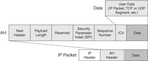
In the figure, if the connection is using tunnel mode, the first IP packet is considered the user data; if the connection is using transport mode, just the transport layer header and payload are considered user data. The "Connection Modes" section discusses these two connection modes in more depth. The user data is appended to an AH header.
Here's a description of the fields found in the AH header:
- Next header This field specifies the protocol of the data being encapsulated (like 6 for TCP or 17 for UDP); these numbers are defined by the IANA.
- Payload length This field defines the length of only the AH header and excludes the outer IP header and the encapsulated data.
- Reserved This field is currently reserved and not used.
- Security parameter index (SPI) This field uniquely identifies the connection to a remote peer with a numerical value; it is a number assigned by the receiving device for the unidirectional connection so that it can differentiate traffic from this connection compared to other connections from this or other peers. This field is 4 bytes in length, allowing for over a billion identifiers for SPI values on a device.
- Sequence number This field specifies a number unique to each packet traversing the data connection and is used to detect replay attacks.
- Integrity checksum value (ICV) This field provides authentication information for the packet; it is the digital signature created from the MD5 or SHA-1 HMAC function. The ICV value is created by taking all of the fields in the complete IP packet (IP packet header, minus the mutable fields, the AH header, minus the ICV field, and the user data), along with the shared HMAC key, and running it through an HMAC function. The peer at the other end can verify the integrity and origin of the packet assuming the remote peer knows about the same HMAC key.
One of the things you've probably noticed is that AH doesn't perform encryption as one of its protection services; therefore, it has limited use when you need to transmit data across public networks. Plus, AH doesn't work with NAT or PAT, for the following reasons:
- PAT needs a TCP or UDP outer header and AH is a Layer-3 protocol.
- NAT changes the source or destination IP addresses; but AH uses these when creating the ICV value.
Therefore AH is commonly used inside a network, typically with connections using transport mode, as between an internal router and a syslog server or a PIX and a TFTP server. I'll discuss address translation issues in more depth later in the "Address Translation Issues" section of this chapter.
ESP
ESP, defined in RFC 2406, provides Layer-3 protection of data. It has an IP protocol number of 50 and offers the same type of services that AH provides, but with two exceptions:
- ESP provides encryption of the user data.
- ESP's data authentication and integrity service include only the ESP header and payloadnot the outer IP header. Therefore, if someone were to tamper with the outer IP header, ESP wouldn't detect this (AH could); of course if your ESP traffic is going through a NAT device, this is an advantage.
Figure 3-7 shows the process ESP performs on user data to protect it between two IPsec peers. Depending on whether the connection mode is transport or tunnel, the upper layer data or the first IP packet is padded. The padding is used to reduce the likelihood of an eavesdropper guessing what the payload is based on its length. The length is added to this information, then the next header denotes the contents of the payloadthis is the same field used by AH.
Figure 3-7. ESP Packetization Process
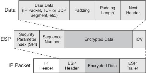
Typically the information is then encrypted and an ESP header and, optionally, a trailer, are added. The SPI field serves the same purpose it does with AH: it uniquely identifies each IPsec data connection terminated on a device. The sequence number is used to prevent replay attacks. Optionally, if you have enabled packet authentication, an ICV value is added at the end of the encrypted data. The ICV value is created by taking the ESP header, the encapsulated data, and a key, and running them through an HMAC function (creating a digital signature). An IP header is then added to the front of the ESP header to transport the information to the remote IPsec device.
When a remote IPsec peer receives ESP information, it performs the process in reverse. If authentication is used, the ICV value is verified. If valid, the encrypted data is decrypted. This makes sense, because there is no point in wasting extra CPU cycles to decrypt something if it has been tampered with.
Note
AH and ESP are not mutually exclusive of one another; they can be used in conjunction with each other because ESP provides encryption and AH provides better protection for data authentication and integrity. However, because AH has problems with intermediate devices changing information in the outer IP header, it is typically not used in public networks.
Phase 2 Connection Modes
As I mentioned in the last two sections, there are two types of modes that AH and ESP can use to transport protected information to a destination:
- Transport mode
- Tunnel mode
In transport mode, the real source and destination of the user data are performing the protection service. It becomes more difficult to manage as you add more and more devices using this connection mode. This mode is commonly used between two devices that need to protect specific information, like TFTP transfers of configuration files or syslog transfers of logging messages.
In tunnel mode, intermediate devices (typically) are performing the protection service for the user data. This connection mode is used for site-to-site and remote access connections. Because the original IP packet is protected and embedded in AH/ESP and an outer IP header is added, the internal IP packet can contain private IP addresses. Plus, if you're using ESP for encryption, the real source and destination of the user data is hidden from eavesdroppers. The main advantage of tunnel mode over transport mode is that the protection service function can be centralized on a small number of devices, reducing the amount of configuration and management required. Both of these modes were discussed in detail in Chapter 1, "Overview of VPNs."
Phase 2 Transforms
A data transform defines how the data connections should be protected. If you recall from the "ISAKMP/IKE Transforms" section earlier, to protect the management connection, an ISAKMP/IKE transform or transforms is defined. The same is true of the data connections in ISAKMP/IKE Phase 2. However, management transform sets and data transform sets contain different information. A data transform set contains the following information about how to protect traffic between IPsec peers:
- The security protocol: AH and/or ESP
- The connection mode for the security protocols: tunnel or transport (if you're using both AH and ESP, you must use the same connection mode for both)
- For ESP, encryption information: no encryption algorithm, DES, 3DES, AES-128, AES-192, or AES-256
- The packet authentication and verification HMAC function: MD5 or SHA-1 (with ESP, this is optional)
Data Connections
As mentioned in the "IPsec Connections" section earlier, a security association (SA) groups all of the necessary security components to communicate successfully with an IPsec peer. With data SAs, you'll have one data SA, per direction, per protected pipe. For example, if you were using only ESP for protection between two peers, you'd have two SAs: one for each peer. However, if the peers were using both AH and ESP, you'd have two SAs per peer: one for AH and one for ESP on both peers. Therefore, you can't really look at an SA as a "connection," because you could be using both AH and ESP to provide protection. Both would be separate SAs, but with one single connection to a remote peer. The following two sections will discuss the components of a data SA and how data SAs are negotiated.
Components of a Data SA
Here are the components you'll find in a data SA:
- The security protocol: AH and/or ESP.
- The SPI value for AH and/or ESP (this is assigned by the receiving device for a data connection).
- The connection mode for AH and/or ESP: tunnel or transport (you must use the same mode if using both AH and ESP).
- The lifetime of the SA: the lifetime can be measured in time (seconds) or amount of data transferred (KBs).
- The packet authentication and integrity HMAC function for AH and/or ESP, and the symmetric key(s): MD5 or SHA-1. The symmetric key used here is different from the one used in the ISAKMP/IKE Phase 1 management connection; actually a separate key can be used for each data connection.
- The encryption algorithm and symmetric key used if ESP is chosen: null (none), DES, 3DES, AES-128, AES-192, and AES-128. The symmetric key used here is different from the one used in the ISAKMP/IKE Phase 1 management connection; actually, there could be different keys for each data connection.
- Perfect Forward Secrecy (PFS) usage: By default, the existing ISAKMP/IKE Phase 1 management connection is used to share the encryption and HMAC symmetric keys; optionally, you can use Diffie-Hellman to do this. DH is more secure than the management connection because of the length of the key structure. For example, 3DES uses 168 bits and DH group 1 is 768 bits. However, the downside of using PFS is that there is more delay in using DH to share the data connection keys than using the existing management connection.
How Data SAs Are Negotiated
Once ISAKMP/IKE Phase 1 completes, the management connection is used for the two peers to communicate to each other with ISAKMP/IKE messages. The negotiation of the ISAKMP/IKE Phase 2 connections is done across the management connection. Each peer shares the following with its remote counterpart:
- The traffic that needs to be protected with the other peer (on Cisco routers and PIX and ASA security appliances, this is commonly called a crypto ACL).
- The list of data transforms that can be used to protect the traffic (the order is important because they are processed in the order that they are receivedtherefore, put the most secure transform at the beginning of the list and the least secure at the end). In a transform, you'll find the following: the security protocol (AH or ESP), the packet authentication and integrity HMAC function, the encryption algorithm, and the connection mode.
- Whether or not PFS should be used. If it is used, the DH key group needs to be negotiated.
- The local IP address that should be used in the outer header of the IP packet.
- The measurement of the lifetime, in seconds and/or KBs.
Let's look at a simple example of how the negotiation process takes place. Assume IPsecA has the following transforms:
|
1. |
Transform 1A: AH with MD5, ESP with AES-256, tunnel mode |
|
2. |
Transform 2A: ESP with MD5, ESP with AES-128, tunnel mode |
IPsecB has the following transforms:
|
1. |
Transform 1B: ESP with MD5, ESP with AES-128, tunnel mode |
|
2. |
Transform 2B: ESP with MD5, ESP with 3DES, tunnel mode |
Who makes the connection (remember, they're unidirectional) affects how the transforms are processed. The receiving device compares the first transform of the sending device with all of the transforms of the receiving device. If no match is found, the second transform of the sending device is compared with the transforms of the receiving device. This is done in both directions for the two unidirectional connections.
For example, IPsecA, acting as the receiving device, compares Transform 1B to 1A. There isn't a match, so it then compares 1B to 2A. In this case, a matching transform is found and this is used for the unidirectional connection from IPsecB to IPsecA. The same process takes place on IPsecB for the unidirectional connection from IPsecA to IPsecB.
Assuming that there is a matching transform, other things need to be compared or negotiated, such as the traffic that should be protected, the lifetime of the data SAs, and the DH key group to use for PFS, if this is specified and can be negotiated. If this information cannot be negotiated successfully, the data SA setup process fails and no user data can be transmitted between the two IPsec peers.
Note
The one thing that doesn't necessarily have to match between the two peers is the lifetime of the data connections. If there is a mismatch in the lifetime, the two IPsec peers should negotiate and use the lower value between them. However, some vendors don't follow this guideline; for those vendors you'll need to also match the lifetime values.
Part I: VPNs
Overview of VPNs
- Overview of VPNs
- Traffic Issues
- VPN Definition
- VPN Components
- VPN Designs
- VPN Implementations
- VPNs: Choosing a Solution
- Summary
VPN Technologies
IPsec
- IPsec
- IPsec Standards
- ISAKMP/IKE Phase 1
- ISAKMP/IKE Phase 2
- IPsec Traffic and Networks
- Summary
PPTP and L2TP
SSL VPNs
Part II: Concentrators
Concentrator Product Information
- Concentrator Product Information
- Concentrator Models
- Concentrator Modules
- Concentrator Features
- Introduction to Accessing a Concentrator
- Summary
Concentrator Remote Access Connections with IPsec
- Concentrator Remote Access Connections with IPsec
- Controlling Remote Access Sessions to the Concentrator
- IPsec Remote Access
- Network Access Control (NAC) for IPsec and L2TP/IPsec Users
- Summary
Concentrator Remote Access Connections with PPTP, L2TP, and WebVPN
- Concentrator Remote Access Connections with PPTP, L2TP, and WebVPN
- PPTP and L2TP Remote Access
- WebVPN Remote Access
- Summary
Concentrator Site-to-Site Connections
- Concentrator Site-to-Site Connections
- L2L Connectivity Example
- ISAKMP/IKE Phase 1 Preparation
- Adding Site-to-Site Connections
- Address Translation and L2L Sessions
- Summary
Concentrator Management
- Concentrator Management
- Bandwidth Management
- Routing on the Concentrator
- Chassis Redundancy
- Administration Screens
- Summary
Verifying and Troubleshooting Concentrator Connections
- Verifying and Troubleshooting Concentrator Connections
- Concentrator Tools
- Troubleshooting Problems
- Summary
Part III: Clients
Cisco VPN Software Client
- Cisco VPN Software Client
- Cisco VPN Client Overview
- Cisco VPN Client Interface
- IPsec Connections
- VPN Client GUI Options
- VPN Client Software Updates
- VPN Client Troubleshooting
- Summary
Windows Software Client
- Windows Software Client
- Windows Client
- Configuring the Windows VPN Client
- Configuring the VPN 3000 Concentrator
- Microsoft Client Connections
- Troubleshooting VPN Connections
- Summary
3002 Hardware Client
- 3002 Hardware Client
- Overview of the 3002 Hardware Client
- Initial Access to the 3002
- Authentication and Connection Options
- Connection Modes
- Administrative Tasks
- Summary
Part IV: IOS Routers
Router Product Information
Router ISAKMP/IKE Phase 1 Connectivity
- Router ISAKMP/IKE Phase 1 Connectivity
- IPsec Preparation
- ISAKMP/IKE Phase 1 Policies
- ISAKMP/IKE Phase 1 Device Authentication
- Monitoring and Managing Management Connections
- Routers as Certificate Authorities
- Summary
Router Site-to-Site Connections
- Router Site-to-Site Connections
- ISAKMP/IKE Phase 2 Configuration
- Viewing and Managing Connections
- Issues with Site-to-Site Connections
- Summary
Router Remote Access Connections
- Router Remote Access Connections
- Easy VPN Server
- Easy VPN Remote
- IPsec Remote Access and L2L Sessions on the Same Router
- WebVPN
- Summary
Troubleshooting Router Connections
- Troubleshooting Router Connections
- ISAKMP/IKE Phase 1 Connections
- ISAKMP/IKE Phase 2 Connections
- New IPsec Troubleshooting Features
- Fragmentation Problems
- Summary
Part V: PIX Firewalls
PIX and ASA Product Information
- PIX and ASA Product Information
- PIX Deployment Scenarios
- PIX and ASA Feature and Product Overview
- Summary
PIX and ASA Site-to-Site Connections
- PIX and ASA Site-to-Site Connections
- ISAKMP/IKE Phase 1 Management Connection
- ISAKMP/IKE Phase 2 Data Connections
- L2L Connection Examples
- Summary
PIX and ASA Remote Access Connections
- PIX and ASA Remote Access Connections
- Easy VPN Server Support for 6.x
- Easy VPN Remote Support for 6.x
- Easy VPN Server Support for 7.0
- Summary
Troubleshooting PIX and ASA Connections
- Troubleshooting PIX and ASA Connections
- ISAKMP/IKE Phase 1 Connections
- ISAKMP/IKE Phase 2 Connections
- Summary
Part VI: Case Study
Case Study
Index
EAN: 2147483647
Pages: 178
