IPsec Remote Access
Now that you have a basic understanding of some of the global tasks you'll perform no matter what type of remote access sessions will be terminating on your concentrator, the remainder of this chapter will focus on the setup of IPsec remote access sessions. If you recall from Chapter 3, "IPsec," IPsec is one standard that defines how to protect traffic between devices. It supports site-to-site and remote access connectivity. For remote access sessions, the following steps are performed to build a tunnel:
|
1. |
Negotiate the ISAKMP/IKE Phase 1 transform set. |
|
2. |
Perform Diffie-Hellman (DH) to come up with the shared secret key, and use this to encrypt the encryption key and HMAC function key to share between the peers. |
|
3. |
Perform device authenticationconcentrators only support pre-shared keys and digital certificates with a CA. |
|
4. |
Authenticate the user using XAUTH. |
|
5. |
Apply access policies to the user, such as assigning the user an internal IP address, defining split tunneling and split DNS usage, enforcing a firewall policy, and so on. Cisco commonly calls this step either IKE Mode Config or IKE Client Config. |
|
6. |
You can use reverse route injection (RRI) to advertise the client's internal addressing information; this is necessary if the following are true: - The client could connect to more than one concentrator at the corporate site and local address pools are not being used to assign addressing information to the client. - The client is a hardware client in network extension mode and needs to advertise the address of its private or inside interface to the corporate office. |
One of the issues of IPsec is that for remote access connections, how policies are applied to a client are not defined by the IPsec standardeach IPsec vendor does this differently. Therefore, when I explain how to configure Step 5 later in this chapter, it is specific to the Cisco implementation. Also, I'll cover Step 6 in Chapter 14, "3002 Hardware Client," Chapter 18, "Router Remote Access Connections," and Chapter 22, "PIX and ASA Remote Access Connections." This chapter will focus on the configuration of remote access software clients on the concentrator.
This part of the chapter will discuss:
- Configuring ISAKMP/IKE Phase 1 transform sets (proposals) for the management connection of IPsec clients.
- Defining device authentication.
- Configuring the group's general IPsec policies.
- Configuring the group's IKE Mode Config policies.
- Setting up IPsec client firewall policies.
- Configuring ISAKMP/IKE Phase 2 data transform sets.
ISAKMP/IKE Phase 1: IKE Proposals
The first configuration items I'll explain are how to configure Steps 1 and 2: negotiating the Phase 1 transforms and the use of DH to build the secure management connection. On the concentrator, this is referred to as setting up your "IKE Proposals or Policies." The following two sections will discuss how to set up your IKE proposals.
IKE Proposal Screen
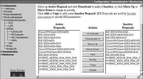
To define and use IKE Phase 1 proposals, go to Configuration > Tunneling and Security > IPsec > IKE Proposals. This screen is shown in Figure 7-18. The screen is broken into three columns:
- Active Proposals These are management transform sets that can be used to protect the ISAKMP/IKE Phase 1 management connection between the concentrator and another device, like a remote access client or an L2L peer.
- Actions These are actions that can be performed on a selected management transform set.
- Inactive Proposals These are management transform sets that have been created, but are not being used in the negotiation process between the concentrator and another IPsec device.
Figure 7-18. IKE Proposal Listings
Note
In Versions 4.0 and earlier of the concentrator software, to reach the IKE Proposal screen, go to Configuration > System > Tunneling Protocols > IPsec > IKE Proposals. Also, the term "proposal" when dealing with the concentrator is synonymous with the IKE Phase 1 management transform set.
Proposal Names
Each management transform set is given a descriptive name. For example, the first management transform set listed under the Active Proposals column is "CiscoVPNClient-3DES-MD5." Based on the Cisco predefined name, it is fairly simple to figure out what the transform is used for: Cisco Easy VPN Remote/Client products with 3DES encryption and MD5 HMAC function. Here is a list of typical uses of transform sets based on Cisco nomenclature:
- Names beginning with "CiscoVPNClient" or "HYBRID" are used by Cisco client products.
- Names ending in "DH7" are used by Certicom's Movian VPN client for PDAs.
- Names beginning with IKE are used for site-to-site or other remote access client products.
Note
Certicom's client has been discontinued. There are currently other vendors working on third-party replacement products. One of these vendors is Worldnet21, which recently purchased the Movian source code.
Action Buttons
When you click a proposal name in either column, you can then perform an action on the proposal from the Action buttons. Here's a brief explanation of each of these buttons:
- Activate Takes a selected proposal from the Inactive column and moves it over to the Active column.
- Deactivate Takes a selected proposal from the Active column and moves it over to the Inactive column.
- Move Up Moves a selected proposal set up in the list of proposals; this is important for the Active column because proposals are used in the order listed . . . top-down. Therefore order is important; the most secure entries should be at the top and the least secure at the bottom. However, the ones beginning with "CiscoVPNClient" should appear before the ones that begin with "IKE."
- Move Down Moves a selected set of proposals down in the list of proposals.
- Add Adds a new proposal (you don't have to select any proposal name when adding a new one).
- Modify Modifies a selected proposal.
- Copy Copies a selected proposal; this is useful when you need to create two proposals that are very similar.
- Delete Deletes a selected proposal.
IKE Proposal Components
If you choose to add or modify an IKE proposal, you are taken to the screen shown in Figure 7-19. In this example, I'm adding a new proposal. You must give the proposal a unique name (the name has local significance only). The name can include spaces and is case-sensitive; it can be up to 48 characters in length. Following the name, you need to choose an Authentication Mode, which specifies how authentication (device and user) is to be performed.
Figure 7-19. IKE Proposal Components
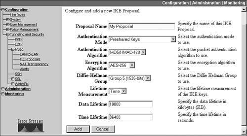
Table 7-2 lists the authentication modes you can specify. Hybrid authentication is new in concentrator software Version 4.1.4 and the VPN Client 4.0.5 software. Remember that the modes that have "XAUTH" or "HYBRID" in them are for IPsec remote access sessions only. Hybrid mode uses certificates to perform device authentication (on the concentrator only) and then the group's pre-shared key to validate a user's access to a groupon the VPN Client, this is referred to as "mutual group authentication."
|
Authentication Mode |
Uses |
Description |
|---|---|---|
|
Pre-shared Keys |
Site-to-site and some non-Cisco remote access clients |
A pre-shared key is used for device authentication |
|
RSA Digital Certificate |
Site-to-site and some non-Cisco remote access clients |
An RSA certificate is used for device authentication |
|
DSA Digital Certificate |
Site-to-site and some non-Cisco remote access clients |
A DSA certificate is used for device authentication (DSA algorithm used to generate keys) |
|
Pre-shared Keys (XAUTH) |
Remote access clients |
A pre-shared key is used for device authentication, with XAUTH for user authentication |
|
RSA Digital Certificate (XAUTH) |
Remote access clients |
An RSA certificate is used for device authentication, with XAUTH for user authentication |
|
DSA Digital Certificate (XAUTH) |
Remote access clients |
A DSA certificate is used for device authentication, with XAUTH for user authentication |
|
RSA Digital Certificate (HYBRID) |
Cisco remote access clients |
An RSA certificate is used for device authentication, with XAUTH for user authenticationthe group's pre-shared key also is used to authenticate a user's access to a specific group |
|
DSA Digital Certificate (HYBRID) |
Cisco remote access clients |
A DSA certificate is used for device authentication, with XAUTH for user authenticationthe group's pre-shared key also is used to authenticate a user's access to a specific group |
|
CRACK |
Nokia 92xx IP phones |
A challenge/response authentication method using cryptographic keys is supported in 4.7 for Nokia phones |
Below the Authentication Mode parameter, you can choose the HMAC function to use for packet integrity checking: MD5 or SHA-1. Your choices for an encryption algorithm are: DES, 3DES, AES-128, AES-192, and AES-256. For DH groups, the concentrator supports 1, 2, 5, and 7, with 5 being the most secure. The lifetime of the management connection can be measured in time or amount of kilobytes sent across it. Most administrators use time for the measurement, where the default lifetime is 86,400 seconds (1 day) for the management connection.
Tip
In today's world of computers, I would recommend one of the AES algorithms because they are more secure and less computationally intensive than their DES counterparts. Remember that even though SHA-1 is more secure, IPsec uses only 96 bits of the signature, making MD5 and SHA-1 basically equivalent.
If this is a new proposal, click the Add button at the bottom; for changes to an existing proposal, click the Apply button at the bottom. As you can see, setting up the management transform set is a fairly simple process with the concentrator's web-based interface and drop-down selectors.
Note
When you add a new proposal, it will show up in the Inactive column; therefore, you'll need to activate it and put it in the proper place in the Active column.
ISAKMP/IKE Phase 1: Device Authentication
Once you have set up your IKE proposals, you're now ready to define your authentication information based on what you've specified in your IKE proposal(s). As you saw in the last section, only two basic types of device authentication are supported: pre-shared keys and digital certificates. The next two sections will discuss the use of both of these.
Pre-Shared Keys
Of the two device authentication methods, setting up pre-shared keys is definitely the easiest. You'll need to do this if the authentication mode you chose in your IKE Proposal was either pre-shared keys or HYBRID. Defining a pre-shared key is done on a group-by-group basis. First access the group screen: Configuration > User Management > Groups. Next, select a group and click the Modify button. Within the Identity tab, as shown previously in Figure 7-3, enter the pre-shared key twice: once in the "Password" field and once in the "Verify" field. Then click the Apply button at the bottom to accept your changes.
Digital Certificates
Using certificates on the concentrator for device authentication is much more complex than using pre-shared keys; but it is a more secure method of authentication. Certificates are required if you chose a proposal that included DSA, RSA, or HYBRID. First, you must obtain two certificates for the concentrator: root and identity. Do this using either the file-based or network-based (SCEP) approach. Also, you can configure some parameters related to the use of CRLs and certificate group matching. Last, make sure that you have a corresponding IKE Proposal that specifies the user of certificates for device authentication. The following sections cover the configuration of these steps on the concentrator.
Allowing External Access to the CA
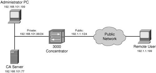
This step might not be necessary; however, let's examine Figure 7-20 to illustrate a problem that you might experience with using a CA. In Figure 7-20, the CA is internal to the network design. This is not a very common implementation; normally, the CA would be placed in a DMZ and a firewall would restrict access to it. However, in my example, the CA is internal and, by default, the concentrator denies HTTP access from the public interface. Therefore, remote access clients won't be able to access the CA to validate other devices' certificates, including the concentrator itself. In this situation, you need to modify the filter on the concentrator's public interface to allow HTTP access inbound and outbound from the CA, assuming that the CA is not located off the private interface of the concentrator. I discuss this process in more depth in Chapter 10, "Concentrator Management."
Figure 7-20. Internal CA
Obtaining a Certificate: File-Based
There are two methods you can use to obtain the root and identity certificates on your concentrator: file-based and network-based. This section will talk about the former. Here are the steps you'll go through:
|
Step 1. |
Assign a hostname by going to Configuration > System > General > Identification; the hostname is entered into the System Name text box. The name must be DNS-friendly. |
|
Step 2. |
Assign a domain name by going to Configuration > System > DNS Servers and entering a domain name in the Domain text box. A fully qualified domain name is needed to generate the public/private keys that are used to sign and validate the identity certificate. |
|
Step 3. |
Go to Administration > Certificate Management > Enrollment. Click the Enroll via PKCS10 Request (Manual) hyperlink. |
|
Step 4. |
You now need to enter the PKCS #10 information for the concentrator. This screen is shown in Figure 7-21. The only required field is Common Name, where you typically enter the fully qualified DNS name of the concentrator (you can enter a single name, though). The other fields are optional. One field that doesn't appear on the screen shot, but is at the bottom of the screen, is Key Size, which allows you to specify the size of the public/private keys to generate. The default is 512 bits, but this can be 768, 1024, and 2048. When finished filling out the PKCS #10 enrollment form, click the Enroll button at the bottom of the screen. Figure 7-21. Certificate PKCS #10 Enrollment 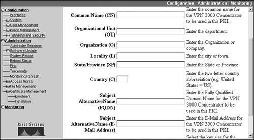
|
|
Step 5. |
A web browser window will pop up with the PKCS information that you need to send, out-of-band, to the CA administrator. Figure 7-22 displays the web browser window with the PKCS #10 information. This file also is stored in Flash memory of the concentrator, so if you accidentally close this window, you still can recall the PKCS #10 information. Please note that you need to send the entire contents, including the lines that begin with "---." Figure 7-22. PKCS #10 File 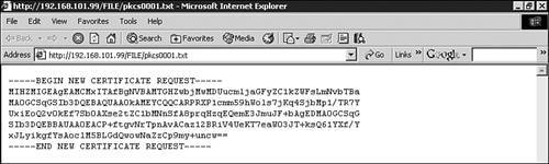
|
|
Step 6. |
The CA administrator will send back two certificates (typically out-of-band): the root and your concentrator's new identity certificates. You must install the root certificate first. To install the root certificate, go to Administration > Certificate Management > Installation. Click the Install CA Certificate hyperlink. |
|
Step 7. |
Click the Upload File From Workstation hyperlink. Click the Browse button and find the CA's root certificate on your PC's hard drive. Click the Install button to install the root certificate. You'll be returned to the Administration > Certificate Management screen. I'll discuss this screen in Step 10. |
|
Step 8. |
Now you need to install your identity certificate. Go to Administration > Certificate Management > Installation. Click the Install certificate obtained from enrollment hyperlink. The Enrollment Status screen is displayed, as shown in Figure 7-23. As you can see, the status is "In Progress." Figure 7-23. Enrollment Status Screen 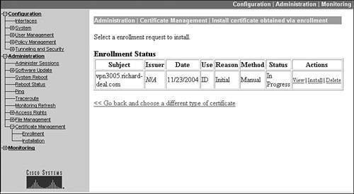
|
|
Step 9. |
Click the Install hyperlink. Click the Upload File From Workstation hyperlink. Click the Browse button and find the concentrator's identity certificate on your PC's hard drive. Click the Install button to install the root certificate. |
|
Step 10. |
You'll be returned to the Administration > Certificate Management screen, shown in Figure 7-24. From this screen you can see the root certificate (the Subject is "caserver") and the identity certificate (the Subject is "vpn3005.richard-deal.com"). To view either certificate, click the View hyperlink under the Actions column. Figure 7-25 shows the concentrator's identity certificate. Figure 7-24. Certificate Management Screen 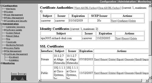
Figure 7-25. Concentrator's Identity Certificate 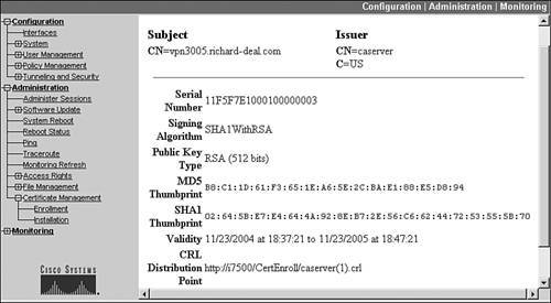
|
This completes the process for certificate file-based enrollment.
Note
The concentrator needs a name and a domain name in order to generate the RSA key pair that will be used to sign and validate the PKCS #10 information.
Obtaining a Certificate: Network-Based
The second method you can use to obtain the root and identity certificates is SCEP. Of the two methods, this is definitely easier than the file-based approach. Here are the steps you'll go through:
|
Step 1. |
Assign a hostname by going to Configuration > System > General > Identification; the hostname is entered into the System Name text box. The name must be DNS-friendly. |
|
Step 2. |
Assign a domain name by going to Configuration > System > DNS Servers and entering a domain name in the Domain text box. A fully qualified domain name is needed to generate the public/private keys that are used to sign and validate the identity certificate. |
|
Step 3. |
Go to Administration > Certificate Management > Enrollment. Click the Click here to install a new CA using SCEP before enrolling hyperlink. |
|
Step 4. |
This screen lets you retrieve the root certificate from the CA, shown in Figure 7-26. You'll need to enter the URL location to access the CA via SCEP. Each vendor has a unique URL for this. In my case, I'm using a Microsoft Windows 2000 Server for the CA, so the URL is: "http://192.168.101.77/certsrv/mscep/mscep.dll". Following this is the descriptor of the CA, which typically is a name. In my case, I entered "caserver." For some CA products, you must use the name configured on the CA: your CA administrator can tell you the correct name. Once you enter this information, click the Retrieve button. Figure 7-26. CA Location for SCEP Access 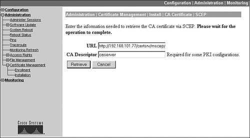
|
|
Step 5. |
If the retrieval process is successful, you should be taken to the Certificate Management screen shown previously in Figure 7-25. In the Certificate Authorities section you should see the root certificate, and the SCEP Issuer column should say "Yes." |
|
Step 6. |
Once you've installed the root certificate, you can proceed to generating your concentrator's PKCS #10 information and using SCEP to send this to the CA and to retrieve its identity certificate. To start the process, go to the Administration > Certificate Management > Enrollment screen. Click the Enroll via SCEP at caserver hyperlink. Please note that your particular situation won't say "caserver," because this is the name of the CA server I used. |
|
Step 7. |
You are taken to the PKCS #10 enrollment screen shown previously in Figure 7-21. You only need to enter the common name (the name of the concentrator) for the certificate. There is one difference between the SCEP PKCS #10 screen and the one in Figure 7-21: the SCEP screen prompts you for an optional challenge password. This password can be used to authenticate your identity certificate request and can be used to verify your identity when you want to revoke the concentrator's identity certificate. When finished filling out the PKCS #10 enrollment form, click the Enroll button at the bottom of the screen. |
|
Step 8. |
On an updated screen, you should see either "SCEP Status: Poll" or "SCEP Status: Installed," indicating a successful submission to the CA. If it says "Poll," the CA was set up to not automatically grant identity certificates; the CA administrator will have to log in to the CA and grant the certificate request. The concentrator will continue to poll the CA until the CA grants or revokes the certificate request. If it says "Installed," the CA automatically generated a certificate for you. |
|
Step 9. |
Go to the Administration > Certificate Management screen, shown in Figure 7-24, to see the installed certificates. From this screen you can see the root certificate (the Subject is "caserver") and the identity certificate (the Subject is "vpn3005.richard-deal.com"). |
This completes the process for certificate network-based enrollment.
Configuring CRL Parameters
By default, the concentrator does not use certificate revocation lists (CRLs). To enable the use of CRLs, or to customize CRL parameters, go to Administration > Certificate Management. This screen was shown previously in Figure 7-25. In the Certificate Authorities section, you'll see the root certificates listed. To the far right of the root certificates is a column called Actions. To configure CRL options for the associated CA, click the Configure button. This will take you to the screen shown in Figure 7-27. At the top of this screen are four tabs:
- Certificate Acceptance
- CRL Retrieval
- CRL Protocol
- CRL Caching
Figure 7-27. CRLs: Certificate Acceptance Tab

Click the tab to take you to the correct CRL configuration area. The default tab is the Certificate Acceptance tab. Here you can accept subordinate CA certificates if your CA implementation uses a hierarchy, and you also can accept identity certificates assigned by the CA(s).
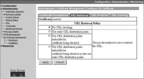
Clicking the CRL Retrieval tab will take you to the screen shown in Figure 7-28. You have the following options:
- You do not want to use CRLs (this is the default).
- You can specify that the concentrator use statically configured CRLs (you specify the URLs for finding the CRL locations).
- You have the concentrator use the CRL listed on the CA's root certificate. If you refer back to Figure 7-25, you'll see the CRL location at the bottom of the root certificate.
- You can have the concentrator use the embedded CRL location on the root certificate; and if this is not reachable, use a static CRL definition(s).
Figure 7-28. CRLs: CRL Retrieval Tab
When you are done making your retrieval policy changes within any of the tabs, click the Apply button at the bottom of the screen.
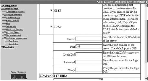
Clicking the CRL Protocol tab takes you to the screen shown in Figure 7-29. This screen allows you to specify which protocol(s) to use to retrieve the CRL: HTTP or LDAP are supported. For LDAP, you must specify the IP address of the server and authentication information. Below this, you can enter up to five URLs for your static CRL definitions/locations.
Figure 7-29. CRLs: CRL Protocol Tab
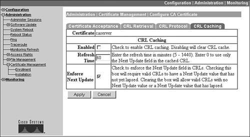
Clicking the CRL Caching tab takes you to the screen shown in Figure 7-30. CRL caching is disabled by default, which means that every time the concentrator needs to reference the CRL, the concentrator has to go out to a URL location and download it, which can be time-consuming. You can enable CRL caching by clicking the Enabled check box. When enabled, a CRL(s) is cached in RAM on the concentrator. Thus, every time you boot up the concentrator, it must go out and download the CRL(s). You can specify how often the concentrator will download the most current CRL(s), and also validate the date on the CRL.
Figure 7-30. CRLs: CRL Caching Tab
Note
There is a trade-off between performance and security when using CRL caching. The advantage, when caching, is that for lengthy CRLs, you can check the validity of a certificate immediately because you have the CRL in RAM. The disadvantage, however, is that if a certificate has been revoked since the last time your concentrator downloaded the CRL, the concentrator will see the certificate as valid. In most cases, I use caching, but I'll set the refresh time to once every hour or so if the CA is an in-house CA. For external CAs, especially public ones like Verisign, I set up a caching refresh time of typically once a day.
Configuring Certificate Group Matching Parameters
Using a certificate for device authentication can present a problem for remote access connectivity: IPsec doesn't define a way of sharing the group name the user wants to use. With pre-shared keys, this is accomplished by sending both the group name and the key for the group, commonly called group keying; but no such method is defined for certificates. Before Version 3.6 of the software, the concentrator used the OU (Organizational Unit), sometimes called the Department, field to represent the name of the group. But this process had limitations: the OU field had to have the correct group name. But what if this was not the case? Or what if a user changed from one group to another? Before 3.6, you would have to reissue a new certificate for the user. Obviously, this is not a flexible solution.
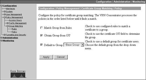
In Version 3.6, the concentrator supports a certificate group matching feature. This feature allows you to look at the values of one or more field on the certificate in order to associate a remote access user to a particular group. To define your group matching policies when certificates are used for device authentication, go to Configuration > Policy Management > Group Matching > Policy, which is shown in Figure 7-31. You have three options:
- Create your own rules as to how matching should occur based on information that appears on a user's identity certificate.
- Use the OU field on the certificate to represent the group name.
- Or, if the above two fail to find a match, put the user in a default group of your choosing.
Figure 7-31. Certificate Group Matching Policies
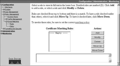
If you enable the first option, you'll need to create your own policy rules for group matching by going to Configuration > Policy Management > Group Matching > Rules, shown in Figure 7-32.
Figure 7-32. Certificate Group Matching Rules Listing
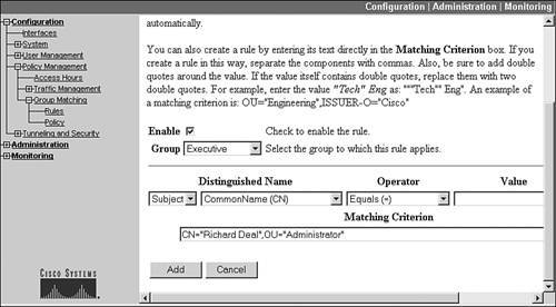
To add a rule, click the Add button, which takes you to the screen shown in Figure 7-33. Click the Enable check box to enable the rule. Used the Group pull-down selector to choose the group that the certificate will be associated with when a match occurs on a rule or rules associated with the group. Below this is a drop-down selector where you either can choose "Subject" (the user) or "Issuer" (the CA); in most cases you'll let it default to "Subject." Next, use the drop-down Distinguished Name (DN) selector to choose the field on the certificate that you want to match on. Next choose the Operator to match on and then the value that appears in the DN field. To the right of this information (cut from the screen shot) is a button labeled Append. Clicking this button will add the match criteria to the section labeled Matching Criterion at the bottom. This feature allows you to look at multiple fields on a certificate to determine which group the user belongs to. Click the Add button when you're done adding your rule, which takes you back to the screen listed in Figure 7-32.
Figure 7-33. Certificate Group Matching Rules Creation
You'll see the rules listed at the bottom of Figure 7-32. The order of the rules is important; because the first match is used by the concentrator when placing a user into a particular group, you can use the Move Up and Move Down buttons to re-sort the list.
Here's a simple example of the use of group matching. Assume you had a user called "Richard Deal," who showed up as this value in the CN field of his identity certificate. Richard currently belongs to the "Administrator" group, but was promoted to an executive position. Your concentrator is using the OU field for group matching, and Richard has "Administrator" in the OU field. However, now that Richard has been promoted, you want him to be placed in the "Executive" group. You can accomplish this by performing the following:
|
Step 1. |
Go to the screen in Figure 7-31 and click the "Match Group from Rules" check box. |
|
Step 2. |
Go to the screen in Figure 7-32 and click the Add button. In Figure 7-33, click the Enable check box and select the "Executive" group. |
|
Step 3. |
Then for the CN, enter "Richard Deal" and click the Append button. |
|
Step 4. |
If there were two Richard Deals, one in the Administrator group and one in the Programming group, you would need to append a second matching criterion like that shown in Figure 7-33: OU=Administrator. |
|
Step 5. |
When done, click the Add button. |
This newly created rule will look for two things on an identity certificate: "Richard Deal" in the CN field and Administrator in the OU field. If there is a match, the user of this identity certificate is associated with the Executive group automatically.
Tip
The most common method of associating a user to a particular group when using certificates is to match on the serial number of the certificate, because each certificate, within a CA's scope of domain, has a unique serial number.
Using Certificates
Once you have obtained your concentrator's identity certificate and want to use certificates for device authentication, the use of certificates by IPsec is defined in three places:
- IKE Proposals (this was discussed in the "IKE Proposal Components" section earlier).
- IPsec tab in the group section (this will be discussed in the "ISAKMP/IKE Phase 1: IPsec Tab" section next).
- Security Association (this will be discussed in the "ISAKMP/IKE Phase 2: Data SAs" section later).
Note
The 3005 supports up to two identity certificates, whereas the other models support up to 20; you need more than one identity certificate if you are using more than one root CA. In this case, you'll need to install a separate root certificate for each root CA and a separate identity certificate (obtained from each individual root CA).
ISAKMP/IKE Phase 1: IPsec Tab
To configure your general IPsec properties for connections, go to either the group or user screen and modify the appropriate value.
Groups IPsec Tab
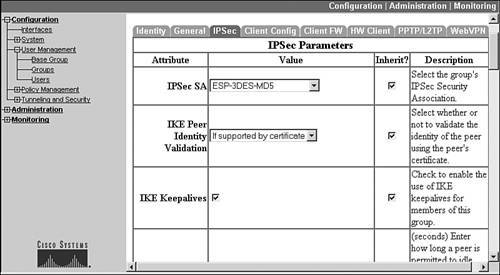
Most of the general IPsec properties for remote access connections are done from the Groups section under User Management: Configuration > User Management > Groups. From here, modify a group and then click the IPsec tab. The top part of the screen you'll see is shown in Figure 7-34. Here is a list of parameters you can change on this screen:
- IPsec SA This pull-down selector allows you to choose the name of the data transform you want to use to protect your unidirectional data connections built in Phase 2 (I discuss the configuration of these later in the "ISAKMP/IKE Phase 2: Data SAs" section).
- IKE Peer Identity Validation This pull-down selector allows you to choose whether or not certificates should be used for device authentication in this group. Your options are:
- If supported by certificate If the client wants to use a certificate and the concentrator has one, use this option.
- Required All users of this group must use certificates for device authentication.
- Do not check When using certificates, don't check the user's identity (in other words, ignore the user's certificate for authentication functions); this is used when the identity certificate is missing some information on the certificate that the concentrator might be expectinguse this option if the client will be using pre-shared keys or the HYBRID method of device authentication.
- IKE Keepalives This check box enables or disables IKE keepalives; this is a proprietary Cisco feature that uses the ISAKMP/IKE Phase 1 management connection to send keepalives periodically to ensure that the connection and peer are still operational. IKE keepalives are supported only on Easy VPN devices.
- Confidence Interval This is the number of seconds the concentrator should allow a peer to idle before beginning IKE keepalives. The value can be from 10300 seconds. For site-to-site sessions, it defaults to 10 seconds; for remote access sessions, it defaults to 300 seconds.
- Tunnel Type This drop-down selector allows you to choose the connection type: "LAN-to-LAN" or "Remote Access." Choose the latter for remote access client sessions (this is the default).
- Group Lock When this check box is checked, the concentrator examines the user's configuration and compares the group name under the user configuration to the group name the user is trying to connect to: if they're different, the user is denied remote access to the concentrator.
- Authentication This drop-down selector allows you to choose the XAUTH authentication method that should be used for the group (in other words, where the user accounts are locatedinternally or on an external server). These can be: "None," "RADIUS," "RADIUS with Expiry," "NT Domain," "SDI," "Kerberos/Active Directory," or "Internal." Use "None" if the group is using L2TP over IPsec or if WebVPN users in the base group are using digital certificates. "RADIUS with Expiry" allows users to change their passwords when they expire: MS-CHAPv2 is used in this process.
- Authorization Type This drop-down selector allows you to choose the authorization method used to authorize users of this group (in other words, where the group policy information is locatedinternally or on an external server). This value can be: "None" (default), "RADIUS," or "LDAP."
- Authorization Required This check box allows you to make authorization a mandatory process; the default is disabled, making it optional.
- DN Field This drop-down selector allows you to specify for IPsec and WebVPN users using digital certificates for authentication, which field in the certificate should be sent to the authorization server to identify the user. The default is "CN otherwise OU," but you can choose other fields on the certificate to represent the identity of the user. This field is used only if you are using authorization for the group.
- IPComp This drop-down selector allows you to enable LZS compression use by a user. This might be useful for dialup remote access clients where you want to maximize bandwidth efficiency. However, enabling this on both the concentrator and client might affect the CPU utilization of the client; therefore, ensure that users of the group only enable this if they are using dialup for remote access. The default for this parameter is "None" for no compression.
- Default Pre-shared Key This parameter appears only in the Base Group configuration. This is used for clients that don't understand the concepts of groups, like Microsoft's Windows XP/2000 L2TP over IPsec client. These clients send only a pre-shared key value (no group name). The pre-shared key can be up to 32 alphanumeric characters in length.
- Reauthentication on Rekey This check box, when selected, specifies that authentication will take place when the ISAKMP/IKE Phase 1 management connection expires and new keying information needs to be generated. Enabling this slows down the rebuilding process, but provides for better security.
- Client Type & Version Limiting This text box field allows you to specify rules to allow or deny client connections based on their type and software version. Rules are entered as follows:
p[ermit] | d[eny] client_type : version
An example would be "p vpn 3002 : 4.0*", which would allow any VPN 3002 running any sub-release of Version 4.0. You don't have to use a space between the client_type, the colon (":"), and the version values. You can enter multiple rules; just put them on separate lines. Rules are processed top-down; if no match is found, the client is denied access for the group automatically. If no rules are defined, there are no restrictions placed on the client type and software version the client uses. This feature needs the client to send the client type and software version information. If they don't, you still can match on this by using "n/a" for the type and version, like this: "p n/a : n/a", which means to permit clients that don't provide a type or version. You are restricted to 255 characters for all of your rules for a group.
- Mode Configuration This check box specifies whether or not IKE Mode/Client Config will take place during ISAKMP/IKE Phase 1 for the group. For non-Cisco clients, it is recommended to unselect this check box, since they don't understand the Cisco IKE Mode/Client Config.
Figure 7-34. Groups IPsec Tab
When you are done making changes to a group, click the Apply button at the bottom of the screen.
Users IPsec Tab
The user configuration also has an IPsec tab. If you go to Configuration > User Management > Users, select a user, and click the Modify button, you're taken into the user's configuration. Inside the user's configuration, click the IPsec tab. Unlike the same tab under the group configuration, the user's configuration has only two options:
- IPsec SA This pull-down selector chooses the data transform to use to protect the data connections for the user; this overrides the group's configuration.
- Store Password on Client This check box, when selected, allows the user to store his XAUTH password locally on his device. This is unchecked (disabled) by default, and I highly recommend that you keep it this way. This parameter overrides the same group parameter found in the group Mode/Client Config tab.
ISAKMP/IKE Phase 1: Mode/Client Config Tab
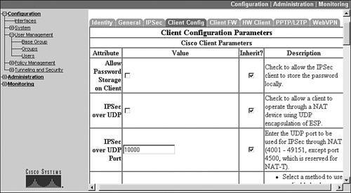
If you recall from the beginning of the "IPsec Remote Access" section, Cisco uses IKE Mode or Client Config to assign policies to Cisco Easy VPN Remotes (clients). This process is Cisco-proprietary. By checking the Mode Config check box from the group's IPsec tab, the parameters under the Client Config tab are used (in older software versions, it was called the Mode Config tab). This section will cover the configuration options available to you under the group's Client Config tab. The top part of this screen is shown in Figure 7-35. Here are your options:
- Allow Password Storage on Client If this check box is checked, the users can store their XAUTH passwords on their client device; it is unchecked, by default, and I highly recommend that you leave it this way.
- IPsec over UDP See the following section entitled "IPsec Tunneling."
- IPsec over UDP Port See the following section entitled "IPsec Tunneling."
- IPsec Backup Servers The pull-down selector allows you to choose three options for this parameter: "Use the List Below," "Use Client Configured List," and "Disable and Clear Client Configured List." If you choose the first option, you can enter, in the text box beneath it, up to 10 IPsec backup Easy VPN Server addresses; this list is then sent to the client during IKE Client Config. If the client already has a list, it is replaced with this list.
- Intercept DHCP Configure Message This check box, when enabled, allows Microsoft clients to implement split tunneling to the concentrator. For XP clients, the concentrator responds with a DHCP Inform message to the client with the subnet mask, domain name, and a classless static route for the tunnel IP address; for older Microsoft clients, the concentrator responds back with a domain name and subnet mask value.
- Subnet Mask The subnet mask to send to Microsoft clients requesting DHCP options (see the last bullet).
- IE Proxy Server Policy See the following section entitled "IE Proxy."
- IE Proxy Server See the following section entitled "IE Proxy."
- IE Proxy Server Exception List See the following section entitled "IE Proxy."
- Bypass Proxy Server for Local Addresses See the following section entitled "IE Proxy."
- Banner This text box allows you to enter a login in a banner for the group. The banner can be up to 510 characters in length and is displayed to Cisco software VPN Clients, WebVPN users, and the 3002 hardware client only during user authentication.
- Split Tunneling Policy See the following section entitled "Split Tunneling."
- Split Tunneling Network List See the following section entitled "Split Tunneling."
- Default Domain Name This text box allows you to assign a domain name to users who authenticate to this group.
- Split DNS Names See the following section entitled "Split DNS."
Figure 7-35. Groups Client Config Tab
The following sections will cover the parameters I did not discuss above, because a more detailed explanation is required for some of the parameter groupings.
IPsec Tunneling
As mentioned in Chapter 3, "IPsec," encapsulated data with AH doesn't work with any type of address translation; therefore, it normally isn't used with remote access VPNs. This is true of the Cisco Easy VPN: Cisco doesn't support it. ESP works fine with NAT, because ESP's packet integrity protection doesn't include the outer IP header; but because ESP is a layer-3 protocol, ESP doesn't work with PAT. As mentioned in Chapter 3, there are three methods you can use to solve PAT problems with ESP, compared in Table 7-3.
|
Encapsulation Method |
Standard |
Description |
Configured |
|---|---|---|---|
|
ESP |
RFC |
Used when no PAT address translation is encountered |
N/A |
|
IPsec Over UDP |
Cisco-proprietary |
Always encapsulates the ESP packet in a UDP header, then adds an outer IP header. This is used when you always know that your remote access client will encounter PAT or a firewall |
Group level |
|
NAT-Traversal (NAT-T) |
RFC |
Encapsulates the ESP packet in a UDP header, then adds an outer IP header only when a PAT device is discovered between the client and gateway; a discovery process is used to test for a device performing PAT |
Global level |
|
IPsec over TCP |
Cisco-proprietary |
Always encapsulates IKE and ESP packets in TCP segments, with an IP outer header added; this process is used when you have issues with IPsec over UDP or NAT-T going through a stateful firewall |
Global level |
The VPN 3000 concentrators can support all four encapsulation methods simultaneously: normal ESP, IPsec over UDP, NAT-T, and IPsec over UDP. If all are enabled, the concentrator looks for a match in this order:
- ESP
- IPsec over TCP
- NAT-T
- IPsec over UDP
The following sections will explain how to configure these on your concentrator.
IPsec over UDP
IPsec over UDP is configured on a group-by-group basis. To enable it, go into a group (Configuration > User Management > Groups) to the Client Config tab. Your two options can be seen in Figure 7-35.
- IPsec over UDP Clicking this check box enables this encapsulation for the group.
- IPsec over UDP Port This is the port number used for the destination UDP port field; it defaults to 10,000, but you can change it to any number from 4,001 to 49,151 except for port 4,500 (which is reserved for NAT-T).
Note
If you have a firewall this traffic travels through, you'll need to allow this UDP port (typically 10,000) through the firewall.
NAT-T
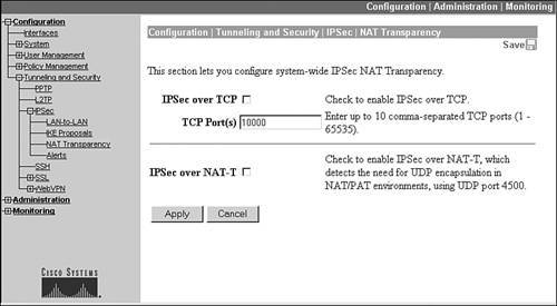
Unlike IPsec over UDP, NAT-T is enabled or disabled globally on the concentrator. To access the concentrator's NAT-T parameters, go to Configuration > Tunneling and Security > IPsec > NAT Transparency. This screen is shown in Figure 7-36. To enable NAT-T, go to this screen and check the IPsec over NAT-T check box.
Figure 7-36. NAT Transparency Screen
The Cisco 3.6 software version (concentrator and hardware and software clients) and later supports NAT-T. If Cisco remote access clients have both IPsec over UDP and NAT-T enabled, NAT-T is used first, then IPsec over UDP is used if NAT-T is not detected (not enabled) on the concentrator; this is common in ISP environments that drop IPsec traffic like ESP, treating this as a business service: they want money to pass this traffic. By encapsulating ESP in IPsec over UDP or TCP, typically you can get around this problem. Microsoft's L2TP/IPsec client also supports NAT-T and site-to-site sessions also can use it (assuming that the end devices support it).
IPsec over TCP
IPsec over TCP is configured globally on the concentrator. To enable it, go to the screen in Figure 7-36. Click the IPsec over TCP check box to enable the process. You can list up to 10 TCP ports, separated by a comma, that clients will use to terminate their TCP-encapsulated ESP connections; the default port number is 10,000.
Note
Please note that IPsec over TCP will not work with proxy-based firewallsonly with packet and stateful filtering firewalls.
IE Proxy
The IE Proxy feature allows the remote access client, assuming it's a Cisco software client, to modify Microsoft's Internet Explorer proxy settings. This option is found under the Client Config tab about halfway down the screen, as shown in Figure 7-37.
Figure 7-37. Groups Client Config Tab: IE Proxy
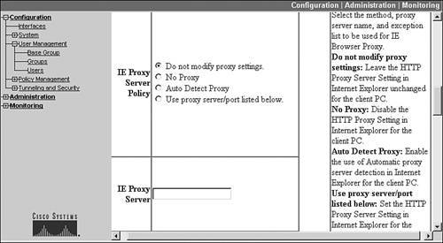
Of the four configuration options you can perform, two are shown in Figure 7-37. The first option, IE Proxy Server Policy, allows you to assign the proxy policy to the client. Your options are:
- Do not modify the proxy settings Leave the client's proxy configuration as it is.
- No proxy Disable the proxy setting on the client.
- Auto detect proxy Enable auto proxy server detection in the clients' Internet Explorer web browser; use this configuration if you want the client to learn the proxy on its directly connected network.
- User proxy server/port listed below Use the proxy server and, possibly, port number listed in the IE Proxy Server text box below this parameter; this configuration is necessary if you want to force Internet Explorer on the client to use a proxy at the corporate site (across the tunnel) instead of one statically configured or dynamically learned from the local LAN segment.
For the last option, in the IE Proxy Server text box, enter the name or IP address of the proxy. If you need to specify a port number, separate the name and port by a colon (":"). Here's a simple example: "proxy.dealgroup.com:8080".
Below the above text box (you can't see this in Figure 7-37) is a parameter called IE Proxy Server Exception List. This text box allows you to create a list of domain names or IP addresses that are exceptions to the proxy process (they won't use the proxy). You can enter wildcards ("*"), and each exception is listed on a separate line. Here is a simple exception example:
www.*.net
172.16.*
In this example, all domain names beginning with "www." and ending in ".net" don't use the proxy and all IP addresses that begin with "172.16." also don't use the proxy. This option typically is used when the web server is at the corporate office and it makes no sense to use the local proxy (split tunneling is enabled).
One more IE Proxy option below this is the Bypass Proxy Server for Local Addresses check box. Like the last option, this creates an exception to using a web proxy; in this case, any local address for web access will not involve a proxy.
Split Tunneling
As discussed in Chapter 1, "Overview of VPNs," split tunneling is a VPN process where some traffic is protected when sent from a client, and some is not. For example, if split tunneling is disabled, all traffic must be sent to a VPN gateway from the client. If the client wants to access his ISP's web servers, when split tunneling is disabled, the following sequence occurs:
|
1. |
The web traffic is protected by the client and sent to the VPN gateway. |
|
2. |
The VPN gateway verifies the traffic and decrypts it, forwarding it back out to the Internet to the client's local ISP. |
|
3. |
The local ISP responds with the web page information to the VPN gateway and the gateway protects this and sends it to the client. |
As you can see in this sequence of steps, for the client to access the local ISP's web server, the traffic has to go all the way to the VPN gateway and back, putting a bigger burden on the two IPsec devices.
The split tunneling feature in Cisco products allows you to define the split tunneling policies at the gateway end and push these, during IKE Mode Config, to the client. Split tunneling on the concentrator is set up in the group section under the Client Config tab about two-thirds of the way down the screen, as shown in Figure 7-38. The following subsections will discuss how to set up split tunneling on the concentrator.
Figure 7-38. Groups Client Config tab: Split Tunneling
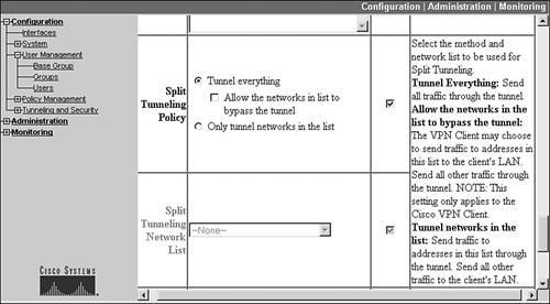
Split Tunneling Options
The Split Tunneling Policy parameter specifies your tunneling policies. The default is "Tunnel Everything," which means split tunneling is disabled and all of the client's traffic must be sent to the concentrator first, in a protected fashion. You have two additional split tunneling options:
- Allow networks in the list to bypass the tunnel
- Only tunnel networks in the list
Both of these parameters refer to the pull-down selector called Split Tunneling Network List at the bottom of Figure 7-38. The network list contains a list of networks. If you choose the first option, then when the client needs to access these networks, it sends traffic in clear text directly to these networks; otherwise, the client protects the traffic and sends it to the concentrator. This option might be useful in a small office where a handful of networks exist, and you want the client to access them directly in a clear-text fashion; but all other traffic should be protected and sent to the concentrator.
If you choose the latter option, only networks in the list are protected and all other traffic is sent out in clear text directly to the destination. An example of this configuration might require all traffic to be protected when accessing the corporate networks, but all other traffic doesn't have to be protected, like accessing the Internet.
Caution
If you enable split tunneling, I highly recommend that for remote access clients, you require them to have a firewall to protect traffic going to and from the clear-text networks; either a software-based firewall or a hardware appliance, like a low-end PIX (501 or 506E).
Network Lists
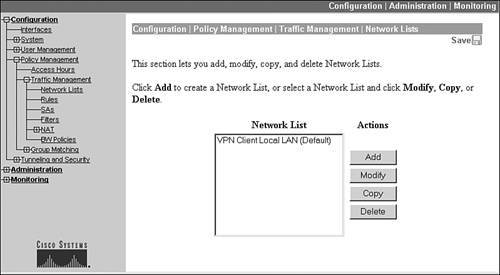
The network list that defines what is or isn't protected is specified with the drop-down Split Tunneling Network List parameter. However, first you need to create a network list before you can select it. To view the existing network lists, go to Configuration > Policy Management > Traffic Management > Network Lists, shown in Figure 7-39. There is one default network list, called "VPN Client Local LAN (Default)," which specifies local LAN traffic based on the IP address and subnet mask applied to the remote access client's NIC.
Figure 7-39. Existing Network Lists
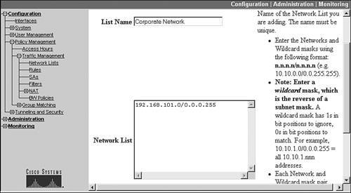
I'll use Figure 7-20 to illustrate a network list example for split tunneling. To add a network list, click the Add button in Figure 7-39. You'll see the screen shown in Figure 7-40. At the top of the screen, enter a unique name for the network list. In this example, I used "Corporate Network." In the Network List text box, enter your network lists. The format is: network_number/wildcard_mask. A wildcard mask is basically an inverted subnet mask. Enter different networks on separate lines. At the bottom of the screen (you can't see it), is a Generate Local List button; clicking this button automatically will populate the Network List text box with the networks off the concentrator's private interface. For the network shown previously in Figure 7-20, I entered a network list entry of "192.168.101.0/0.0.0.255" for the corporate office network. When you are done populating the networks in the Network List text box, click the Add button at the bottom of the screen. You'll be taken back to the screen in Figure 7-39, where you'll see the name of your new network list.
Figure 7-40. Adding a Network List
In my example from Figure 7-20, if you wanted to protect traffic only to the corporate network, and allow the client to send other traffic in clear text, you would go back to the Group's Client Config tab and select Only tunnel networks in the list; then use the pull-down Split Tunneling Network List selector beneath it to pull up the "Corporate Network" list.
Split DNS
By default, during IKE Mode Config, when the concentrator assigns a DNS server to the client, the client will use this over any other configured or obtained DNS server it has locally. This might cause problems where you want to use both servers depending on the destination that is being resolved. I'll use Figure 7-41 to illustrate split DNS. In this example, I'll assume the corporate office's domain name is richard-deal.com.
Figure 7-41. Split DNS Example
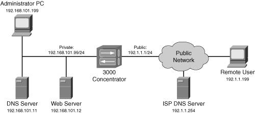
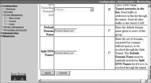
The network administrator wants the remote access clients to use the 192.168.101.11 DNS server when resolving names for the corporate office; but use the ISP's DNS server (192.1.1.254) when resolving any other name. To set this up, go to the Group configuration screen and click the Client Config tab; scroll all the way to the bottom of the screen until you see the Split DNS Names box (see Figure 7-42). In my example, I entered "richard-deal.com", which indicates that the concentrator-assigned DNS server will be used for name resolution of any name ending in ".richard-deal.com", and any other name will be resolved with the ISP's DNS server. You can put multiple domains in this text box; just separate them by commas (and no spaces). Click the Apply button when you're done with the group's configuration changes. Remember that split DNS is used in conjunction with split tunneling: its configuration will not work without split tunneling.
Figure 7-42. Groups Client Config Tab: Split DNS Names
ISAKMP/IKE Phase 1: Client FW Tab
The Client FW tab in the group configuration section allows you to specify a firewall policy for the group. Currently, only the Windows version of the Cisco VPN Client supports this functionality. There are three firewall policies that you can configure:
- Firewall Setting Whether or not a firewall should be used on the client.
- Firewall Product The firewall to be used on the client.
- Firewall Policy The firewall policy the users should use.
The configured firewall policy is pushed down to the client during IKE Mode Config and the Cisco VPN Client software implements the policy. The following sections will discuss each of these three settings.
Firewall Setting
At the top of the Client FW tab you'll find the Firewall Setting parameter, as shown in Figure 7-43. This parameter allows you to specify the use of a firewall. Your options are the following radio buttons:
- No Firewall The client is allowed to connect whether or not a firewall is installed and operational (this is the default option).
- Firewall Required The firewall specified by the Firewall parameter must be installed and operational on the client. The VPN Client polls the firewall every 30 seconds for its operational status; if the firewall is not operational, the VPN Client terminates any existing IPsec session and prevents further IPsec sessions until the specified firewall is operational.
- Firewall Optional The firewall specified by the Firewall parameter is optional on the client. During the IKE Mode Config step, if the VPN Client doesn't detect the specified firewall, a pop-up notification appears, warning the user of the recommended firewall; however, the VPN Client still allows the VPN session to proceed. This option is common when you're migrating users from a no-firewall environment to a required firewall environment.
Figure 7-43. Groups Client FW tab: Firewall Setting
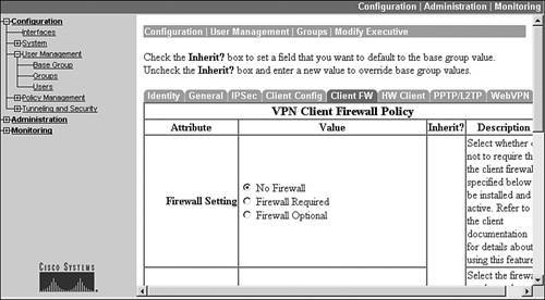
One of the above three options must be chosen.
Note
Currently, there is no way of changing the actual notification message the concentrator sends to the client.
Supported Firewalls
Beneath the Firewall Setting parameter is the Firewall parameter, shown in Figure 7-44. This drop-down selector allows you to choose a firewall that the VPN Client must or should have installed. Supported firewalls include:
- Cisco Integrated Client (CIC) This is a DLL from Zone Labs that provides a free stateful firewall function for Cisco's VPN Client for Windows software; its default policy is to allow outbound traffic, but deny all inbound traffic with the exception of ARP and DHCP messages.
- Cisco Intrusion Protection Security Agent (CSA).
- Zone Labs' ZoneAlarm, ZoneAlarm Pro, and Integrity.
- NetworkICE's BlackIce Defender/Agent.
- Sygate's Personal Firewall, Personal Firewall Pro, and Security Agent.
- Custom FirewallThis feature is used when the VPN Client is running a newer version of code than the concentrator, and thus supports additional firewalls. When this is the case, you choose this option on the concentrator and enter Vendor ID and Product ID values found on the Cisco web site for the firewallthis relieves you from having to upgrade the concentrator to add the additional firewalls the Cisco VPN Client supports.
Figure 7-44. Groups Client FW Tab: Firewall Selection

Firewall Policies
The last firewall parameter required is to choose a firewall policy. There are three firewall policies, as shown in Figure 7-45:
- Policy defined by remote firewall (AYT).
- Policy from Server.
- Policy Pushed (CPP)CPP stands for Central Policy Push or Central Policy Protection.
Figure 7-45. Groups Client FW Tab: Firewall Policy
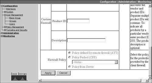
The AYT (are you there) feature has the software client verify that the specified firewall is operational on the client; however, the actual rules the firewall should use are left up to the user to define. With AYT, the VPN Client software polls the firewall every 30 seconds; if the firewall is disabled by the user, and the policy is "Required," the client terminates the VPN session to the concentrator.
The elements in the last two bullet points of the preceding list allow you to define your own firewall rules, and have them pushed down to the client firewall, and have the client firewall use these rules to enforce filtering decisions. The Policy from Server option applies only to users that have Zone Labs Integrity installed. With this firewall product, the users can obtain their firewall filtering rules from a Zone Labs Integrity Server. When choosing this option, you must go to Configuration > System > Servers > Firewalls and configure the Integrity server properties:
- IP address(es) of the Integrity Server(s).
- The Failure PolicyWhat should occur if the Integrity Server cannot be reached: permit or deny user access if the Integrity server(s) cannot be reached.
- Server Port, which defaults to 5054.
- An option to require the Integrity server to authenticate itself with a client SSL certificate.
Policy Pushed (CPP) allows you to push a firewall filter that you've defined on the concentrator to the VPN Client. When you choose this option, you also must specify the name of the filter on the concentrator that will be pushed down to the client during IKE Mode Config. The VPN Client, upon receiving the filter, will have the firewall use this filter and any locally defined filter to filter traffic entering and leaving the user's PC. Currently, only the CIC and Zone Labs' Zone Alarm products support CPP.
If you choose CPP as your firewall policy, you'll need to perform two things on the concentrator:
|
1. |
Create filtering rules that affect traffic coming into and leaving the client. |
|
2. |
Group the rules together in a filter. |
The following two sections discuss both of these items.
Creating Rules
A firewall rule is a statement that defines whether or not a particular type of packet is or is not allowed to come into or leave the client. To view the existing filtering rules, go to Configuration > Policy Management > Traffic Management > Rules, which can be seen in Figure 7-46.
Figure 7-46. Listing of Filtering Rules
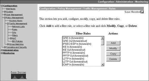
As you can see from this screen, there are a lot of predefined rules on the concentrator; all of these rules are generic in nature: specifying a particular protocol, such as ICMP, or an application, such as HTTP. You can create your own rules by clicking the Add button, taking you to the screen in Figure 7-47. This is only a partial screen shot, but you can be very specific about the information in your new filtering rule.
Figure 7-47. Adding a Filtering Rule
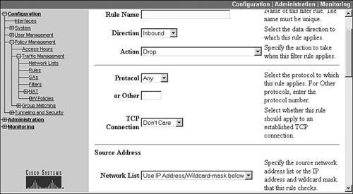
The rule is broken up into sections. At the top, you need to enter a name for the rule. Use a descriptive name that describes what the rule actually does, like "Deny HTTP traffic from 192.168.101.101". Below this is a drop-down selector that allows you to affect the direction of the rule: "inbound" affects traffic coming into the user's computer and "outbound" as traffic leaves the user's computer. Below this is the action the firewall should take when the packet being compared matches the rule:
- Drop (this is the default action if you don't override it)
- Forward
- Drop and Logdrop the packet and create a logging record; use the FILTERDBG event class to find these records in the concentrator's log file (event classes are discussed in more depth in Chapter 10, "Concentrator Management")
- Forward and Log
- Apply IPsecthis option is for site-to-site sessions only and needs to be associated with a specific site-to-site session (data SA)
- Apply IPsec and Log
In my "Deny HTTP traffic from 192.168.101.101" example, you would choose "Drop" or "Drop and Log".
Below the action is the IP protocol that should be examined. There is a drop-down selector where you can choose the name of the protocol, such as ICMP, TCP, UDP, and so on; if the name doesn't appear, you can put in the number of the IP protocol. Use "Any" to match on any IP protocol. For TCP, you specify "Don't care" or "Established" to indicate whether or not you want to include the TCP three-way handshake packets in the filter examination. In my "Deny HTTP traffic from 192.168.101.101", you would choose "TCP" as the IP protocol.
The next two sections are the Source and Destination Address. Here you can have the rule look at a specific source or destination address(es) in packets entering or leaving the user's computer. In each section, you have the option of specifying a network list for the list of addresses or network numbers. See "Network Lists" earlier in the chapter to see how to define a network list. Or you can specify an IP address or network number with a corresponding wildcard (not subnet) mask for each of these sections. In my "Deny HTTP traffic from 192.168.101.101" example, for the source address you would use 0.0.0.0 and a wildcard mask of 255.255.255.255; for the destination address, you would use 192.168.101.101 and a wildcard mask of 0.0.0.0.
Below the source and destination address sections are three protocol sections: TCP/UDP source port, TCP/UDP destination port, and ICMP packet type. For TCP and UDP packets, you can specify a single source or destination port or a range of ports. There is a pull-down selector to choose the name of the port, or you can enter the number (or range of numbers) for the port. For ICMP, you can be specific about the ICMP message type or range of message types of match. In my "Deny HTTP traffic from 192.168.101.101" example, you would leave the TCP/UDP source port information as is (defaults to all ports) and change the TCP/UDP destination port to "HTTP (80)" with the drop-down selector.
When you are done creating a rule, click the Add button at the bottom; this will take you back to the screen in Figure 7-46, where you'll see the name of your new rule.
Tip
I try to be as restrictive as possible with traffic entering and leaving the user's computer when the VPN tunnel is up. For example, many of my filters include rules that block instant messenger communications, peer-to-peer file sharing, and many others which are not business-related, but waste valuable bandwidth. For more information about filtering this kind of traffic using packet filtering rules, see my book entitled Cisco Router Firewall Security, published by Cisco Press.
Creating Filters
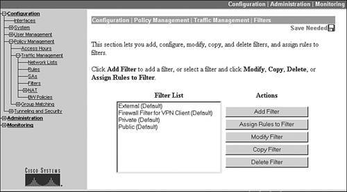
Once you are done creating your rules, you need to group them together into a filter. A filter is similar to an access control list (ACL) on an IOS router, PIX, or ASA. To create a filter, go to Configuration > Policy Management > Traffic Management > Filters (see Figure 7-48) and click the Add button. You must give the filter a name, assign a default action if none of the rules in the filter match a packet (drop, drop and log, forward, or forward and log), allow or deny source routing of packets (I would recommend that you deny source routing), allow or deny fragments (in most cases I would deny fragments), and then give an optional description.
Figure 7-48. Listing of Filters
At the bottom of this screen, click the Add button to add the filter and to assign rules to the new filter (shown in Figure 7-49).
Figure 7-49. Assigning Rules to a Filter
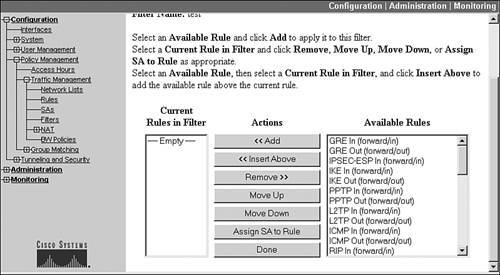
When assigning rules to filters, you'll see three columns on the screen. The left-hand column lists the current rules in the filter. The middle column contains action buttons to perform actions on a selected rule. The right-hand column lists rules you can add to the filter (you must add rules first, otherwise you'll see only the Cisco-defined rules). For example, to add a rule to a filter, in the third column, scroll down to the rule and click it; then click the Add button in the Actions column to add the rule to the left-hand column (Current Rules in Filter). Rules are added to the bottom of the filter, and rules are processed top-down. Therefore, the order of the rules in the left-hand column is important. You can re-sort the rules by clicking a particular rule in the Current Rules in Filter column and then clicking the Move Up or Move Down buttons. The Assign SA to Rule button applies only to site-to-site sessions. When you're done manipulating the rules in your filter, click the Done button in the middle column, taking you back to Figure 7-48.
You can see some default filters on the screen in Figure 7-48. There is one for the private, public, and external interfaces and one called "Firewall Filter for VPN Client (Default)," which can be used for remote access clients. This latter filter allows outbound traffic from the user's computer, but allows only returning traffic back into the user's computer. From the screen in Figure 7-48, you can manipulate the rules for a filter by clicking a filter and then clicking the Assign Rules to Filter button (this takes you to the screen shown previously in Figure 7-49). Remember that firewall filters only affect non-tunneled traffic on the client: you cannot use a firewall filter to filter traffic that will traverse the IPsec tunnel.
ISAKMP/IKE Phase 2: Data SAs
As you can see from the ISAKMP/IKE Phase 1 setup, the concentrator gives you many options to fine-tune your IPsec remote access connectivity. If you're using Cisco products for remote access clients, you probably don't need to worry about setting up the data transform set for ESP; Cisco already has some predefined ones on the concentrator. To see the existing data SA transform sets (or add new ones or modify old ones), go to Configuration > Policy Management > Traffic Management > SAs. There are more than half a dozen predefined data SAs. To create a new one, click the Add button; to modify an existing one, click the name of the transform set and click the Modify button.
Figures 7-50 and 7-51 show an example of modifying a data transform called "ESP-3DES-MD5." This is one of the Cisco default transform sets. As you can see from the name and the screen shots, the name defines how the data connections are protected; however, you can use any name you like. The Inheritance parameter below this has two possible values:
- From Rule One tunnel for each rule is created; thus, many hosts specified in the same rule set can use the same tunnel.
- From Data One tunnel for each address pair (within the rule set) is created.
Figure 7-50. ISAKMP/IKE Phase 2 Data Transforms: Top Screen
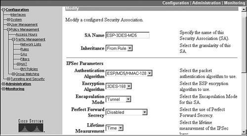
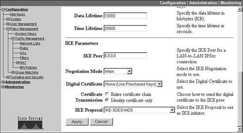
Figure 7-51. ISAKMP/IKE Phase 2 Data Transforms: Bottom Screen
This Inheritance parameter defaults to From Rule, which is the recommended setting and is only applicable to L2L sessions. From Data is more secure because separate address pairs in an L2L session (different internal devices between the two sites) have their own tunnel, and thus their own encryption keys; but this could place a heavy processing burden on the concentrator.
Below the Inheritance parameter is the packet HMAC Authentication Algorithm in the IPsec Parameters section. You can choose either "ESP/MD5/HMAC-128" or "ESP/SHA/HMAC-160." After this is the Encryption Algorithm parameter, which can have values of "DES-56," "3DES-168," "AES-128," "AES-192," "AES-256," and "Null" (no encryption). The Encapsulation Mode parameter can be either "Tunnel" or "Transport." For remote access and L2L sessions, you need to choose "Tunnel." The Perfect Forward Secrecy (PFS) parameter specifies the use of DH to share the data SA's HMAC and encryption keys instead of the ISAKMP/IKE Phase 1 management connection; for Easy VPN, PFS is only recently supported. If enabled, DH groups 1, 2, 5, and 7 are supported. The lifetime of the data connection can be measured in "Time," "Data," "Both," or "None." Below this, you can enter the lifetime in seconds or KBs transferred across the data connection. If you choose "Both," whichever lifetime is reached first causes the data connection to be rebuilt. "None" indicates that unless the data SA is terminated via some other means, it will be disconnected after 86,400 seconds.
The first field in the IKE Parameters section is the IKE Peer; this is used only for L2L sessions and should be left at 0.0.0.0 (any device) for remote access clients. Next is the Negotiation Mode that should be used: "Main" or "Aggressive." If you'll be using digital certificates for device authentication (see the "Using Certificates" section earlier in the chapter), change the Digital Certificate parameter from None to the actual certificate the concentrator should use when performing device authentication with this data SA. If you specified the use of certificates for device authentication, you'll need to choose a Certificate Transmission type:
- Entire Certificate Chain Sent the remote peer the concentrator's identity certificate and all issuing certificates (root CA and subordinate CA certificates).
- Identity Certificate Only This is the default.
Last is the IKE Proposal for ISAKMP/IKE Phase 1 that should be used. Select the Phase 1 transform name from the pull-down selector. When done, click the Apply button at the bottom of the screen.
Part I: VPNs
Overview of VPNs
- Overview of VPNs
- Traffic Issues
- VPN Definition
- VPN Components
- VPN Designs
- VPN Implementations
- VPNs: Choosing a Solution
- Summary
VPN Technologies
IPsec
PPTP and L2TP
SSL VPNs
Part II: Concentrators
Concentrator Product Information
- Concentrator Product Information
- Concentrator Models
- Concentrator Modules
- Concentrator Features
- Introduction to Accessing a Concentrator
- Summary
Concentrator Remote Access Connections with IPsec
- Concentrator Remote Access Connections with IPsec
- Controlling Remote Access Sessions to the Concentrator
- IPsec Remote Access
- Network Access Control (NAC) for IPsec and L2TP/IPsec Users
- Summary
Concentrator Remote Access Connections with PPTP, L2TP, and WebVPN
- Concentrator Remote Access Connections with PPTP, L2TP, and WebVPN
- PPTP and L2TP Remote Access
- WebVPN Remote Access
- Summary
Concentrator Site-to-Site Connections
- Concentrator Site-to-Site Connections
- L2L Connectivity Example
- ISAKMP/IKE Phase 1 Preparation
- Adding Site-to-Site Connections
- Address Translation and L2L Sessions
- Summary
Concentrator Management
- Concentrator Management
- Bandwidth Management
- Routing on the Concentrator
- Chassis Redundancy
- Administration Screens
- Summary
Verifying and Troubleshooting Concentrator Connections
- Verifying and Troubleshooting Concentrator Connections
- Concentrator Tools
- Troubleshooting Problems
- Summary
Part III: Clients
Cisco VPN Software Client
- Cisco VPN Software Client
- Cisco VPN Client Overview
- Cisco VPN Client Interface
- IPsec Connections
- VPN Client GUI Options
- VPN Client Software Updates
- VPN Client Troubleshooting
- Summary
Windows Software Client
- Windows Software Client
- Windows Client
- Configuring the Windows VPN Client
- Configuring the VPN 3000 Concentrator
- Microsoft Client Connections
- Troubleshooting VPN Connections
- Summary
3002 Hardware Client
- 3002 Hardware Client
- Overview of the 3002 Hardware Client
- Initial Access to the 3002
- Authentication and Connection Options
- Connection Modes
- Administrative Tasks
- Summary
Part IV: IOS Routers
Router Product Information
Router ISAKMP/IKE Phase 1 Connectivity
- Router ISAKMP/IKE Phase 1 Connectivity
- IPsec Preparation
- ISAKMP/IKE Phase 1 Policies
- ISAKMP/IKE Phase 1 Device Authentication
- Monitoring and Managing Management Connections
- Routers as Certificate Authorities
- Summary
Router Site-to-Site Connections
- Router Site-to-Site Connections
- ISAKMP/IKE Phase 2 Configuration
- Viewing and Managing Connections
- Issues with Site-to-Site Connections
- Summary
Router Remote Access Connections
- Router Remote Access Connections
- Easy VPN Server
- Easy VPN Remote
- IPsec Remote Access and L2L Sessions on the Same Router
- WebVPN
- Summary
Troubleshooting Router Connections
- Troubleshooting Router Connections
- ISAKMP/IKE Phase 1 Connections
- ISAKMP/IKE Phase 2 Connections
- New IPsec Troubleshooting Features
- Fragmentation Problems
- Summary
Part V: PIX Firewalls
PIX and ASA Product Information
- PIX and ASA Product Information
- PIX Deployment Scenarios
- PIX and ASA Feature and Product Overview
- Summary
PIX and ASA Site-to-Site Connections
- PIX and ASA Site-to-Site Connections
- ISAKMP/IKE Phase 1 Management Connection
- ISAKMP/IKE Phase 2 Data Connections
- L2L Connection Examples
- Summary
PIX and ASA Remote Access Connections
- PIX and ASA Remote Access Connections
- Easy VPN Server Support for 6.x
- Easy VPN Remote Support for 6.x
- Easy VPN Server Support for 7.0
- Summary
Troubleshooting PIX and ASA Connections
- Troubleshooting PIX and ASA Connections
- ISAKMP/IKE Phase 1 Connections
- ISAKMP/IKE Phase 2 Connections
- Summary
Part VI: Case Study
Case Study
Index
EAN: 2147483647
Pages: 178
