Configuring the Windows VPN Client
Once the Windows L2TP/IPsec client is running, you are ready to create a connection profile to protect traffic from the client to the corporate office. Creating a connection profile is done in four steps:
|
1. |
Obtaining certificates (optionalobtaining certificates on Microsoft Windows desktops is beyond the scope of this book; please consult your local Microsoft administrator for more details): for Windows 2000 and earlier, you will need certificates to use L2TP/IPsecpre-shared keys are not supported |
|
2. |
Creating a security policy |
|
3. |
Requiring the use of IPsec for L2TP |
|
4. |
Creating a VPN connection |
The following sections will discuss the last three steps in more depth.
Creating a Security Policy
Before you can create a VPN connection, you'll want to create a security policy. The security policy is used to define the method of authentication, such as pre-shared keys or certificates, and how the connection is protected. Here are the steps to create a security policy that your VPN connection will use:
|
1. |
Go to Start > (Programs) > Administrative Tools > Local Security Policy and click IP Security Policies on Local Machine under the Security Settings heading, shown in Figure 13-2. Figure 13-2. Local Security Settings Window 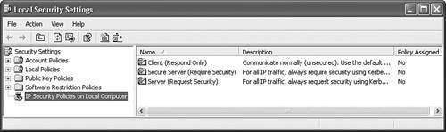
|
|
2. |
Right-click IP Security Policies on Local Machine and choose Create IP Security Policy. |
|
3. |
The IP Security Policy Wizard will begin. Click the Next button to go to the next screen. |
|
4. |
You are taken to the IP Security Policy Name window. Enter the name of the security policy; for example, "Corporate Network Policy." Give it something descriptive that defines what the policy will be used for. Optionally, you can enter a multi-lined detailed description of the policy. Click the Next button when done. |
|
5. |
You are taken to the Requests for Secure Communication window. This window allows you to activate the default response rule to use when the remote VPN gateway requests a security policy that doesn't match any that have been defined. There is only a check box on this screen labeled Activate the default response ruleit is recommended to keep this checked. Click the Next button when done. |
|
6. |
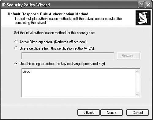
You are taken to the Default Response Rule Authentication Method window, shown in Figure 13-3. Here you define the type of authentication to use with the VPN gateway: Windows 2000 with Kerberos v5, certificates (if you've installed them), or pre-shared keys. In this example, I entered a pre-shared key of "cisco." This also will need to be configured on the VPN gateway. Please note that only through the use of certificates can you use groups on Cisco products, where the OU (Organizational Unit)/Department field contents represent the group name. If you use pre-shared keys, the users will be associated with the Base Group on Cisco concentrators. This is because there is no field in the L2TP/IPsec client which represents a group name when using pre-shared keys. Click the Next button to continue with the wizard. Figure 13-3. Authentication Method
|
|
7. |
Last, you are taken to the Completing the IP Security Policy Wizard window. There is only a check box on this screen, labeled Edit Properties, which is checked. If you click the Finish button, the wizard will complete, but you'll be taken to the Properties window for the policy you just created. |
Edit Properties Windows: Rules Tab
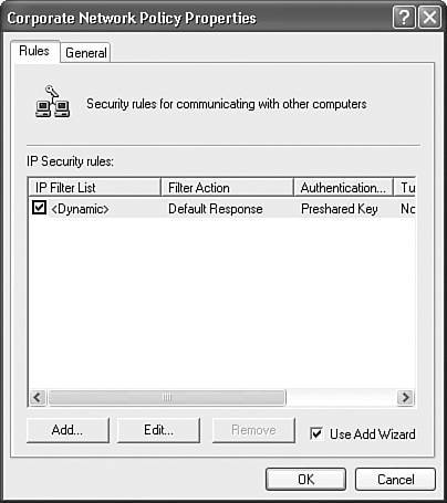
Assuming you left the Edit Properties check box checked on the Completing the IP Security Policy Wizard window, you'll be taken to the Properties window shown in Figure 13-4 (you can also reach this screen by right-clicking the name of the policy in the right-hand column of the Local Security Settings window). The Rules tab will be in the foreground. In the IP Security Rules section, you'll see one default rule, called "." From this screen you can modify the existing rule or create new rules. These rules define how traffic is to be protected based on the destination network to which you are sending it. Normally, you would not need to create more than one rule; however, you might want to edit the default one (""). Click the Edit button to do this.
Figure 13-4. Security Policy Properties Window: Rules
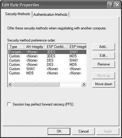
Here you'll see the Edit Rule Properties window shown in Figure 13-5, which displays the security policies, in order, that will be sent from the client to the VPN gateway to protect the IPsec data connections (ISAKMP/IKE Phase 2). You can add new rules, edit existing ones, delete rules, or reorder them, because they are sent in a top-down order to the VPN gateway and processed in this fashion. For sessions to Cisco gateway products, you should use ESP with encryption (3DES or DES) and an HMAC function (SHA or MD5). In the "Configuring the VPN 3000 Concentrator" section later in the chapter, I'll discuss how to set these up on the VPN 3000 concentrators. When adding or editing a rule's properties, you also can specify the lifetime of the data connection. The first policy listed uses ESP with SHA-1 and 3DES, with a data connection lifetime of 3,600 seconds).
Figure 13-5. Edit Rule Properties Window: Security Methods
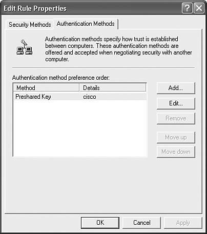
From the Edit Rule Properties window, if you click the Authentication Methods tab, you'll see the window shown in Figure 13-6. You can see the pre-shared key authentication method I defined when adding the security policy. You can add multiple authentication methods, and they are processed in the order listed.
Figure 13-6. Edit Rule Properties Window: Authentication Methods
Note
Only Windows XP systems and higher support pre-shared keys for device authentication; all other Windows systems must use certificates!
Edit Properties Windows: General Tab
In the Properties window shown in Figure 13-4, if you click the General tab, you'll be shown the window in Figure 13-7. If you click the Advanced button, you'll be taken to the window shown in Figure 13-8. You can enable PFS for the ISAKMP/IKE Phase 2 data connections (disabled by default) and change the default lifetime of the ISAKMP/IKE Phase 1 connection, which is 480 minutes (8 hours), but you can modify these.
Figure 13-7. Security Policy Properties Window: General
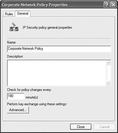
Figure 13-8. Key Exchange Settings Window
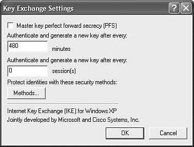
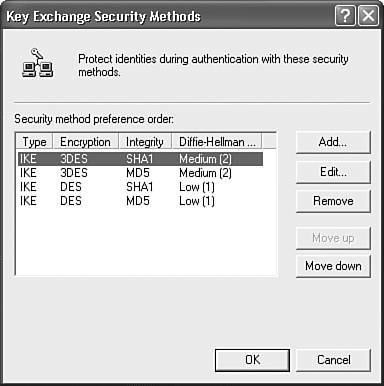
At the bottom of the window is a Methods button, which when clicked, displays the window in Figure 13-9. This is a list of pre-defined ISAKMP/IKE Phase 1 policies to use. At least one of these has to match one on the VPN gateway. You can change the integrity algorithm (SHA-1 or MD5), the encryption algorithm (3DES or DES), and the DH group to use (2 or 1). The first policy listed uses SHA-1, 3DES, and DH group 2 keys.
Figure 13-9. Key Exchange Security Methods Window
Policy Assignment
Once you have created your VPN connection policy, you must activate it for the policy to be used by any VPN connections. Right-click the policy name in the Local Security Settings window shown in Figure 13-2 and select Assign. In the far right-hand column, the Policy Assignment should change from "No" to "Yes."
Requiring the Use of L2TP
To enable your Windows computer to use L2TP instead of L2TP/IPsec (not recommended since MPPE is used for encryption) on Windows 2000 or XP, you must edit your Windows registry. Begin by going to Start > Run and entering regedit in the Open text box; then click the OK button. This opens up the editor for the registry. Then perform the following:
|
1. |
Go to the following place in the registry: |
|
2. |
In the register value window on the right-hand side, right-click and choose New > DWORD Value. For the new value, enter a name of "ProhibitIpSec." |
|
3. |
Then right-click ProhibitIpSec and choose Modify. In the Value data text box, set the value to "1." Then click the OK button. |
|
4. |
Reboot your computer for this change to take effect. |
Caution
Before you begin modifying the Windows registry, I highly recommend that you back it up first! Failure to do this can render the operating system inoperable if you incorrectly edit the registry.
Figure 13-10 shows an example of the registry after this change has been made. If you follow these steps, your Windows 2000 or XP computer will use L2TP without IPsec. However, since most of the Cisco products only support L2TP/IPsec, you should only perform the above when, possibly, connecting to a non-Cisco VPN gateway.
Figure 13-10. Registry Change for Using L2TP/IPsec

Creating a Microsoft VPN Connection
Once you have created your Windows client policy, you are now ready to create your remote access VPN session. The following sections will discuss how this is done.
Initial Connection Setup
Here are the steps to add a new remote access VPN session on your Windows computer:
|
1. |
On a Windows 2000 system, go to: Start > Settings > Network and Dial-up Connections > Make New Connection. On a Windows XP system, go to: Start > My Network Places and click View network connections, and then click Create a new connection. |
|
2. |
You'll be presented with the New Connection Wizard window. Click the Next button. |
|
3. |
For the Network Connection Type options, choose "Connect to the network at my workplace," which allows for the setup of dialup or VPN connections to your corporate office. Click the Next button. |
|
4. |
On this screen there are two options: "Dial-up connection" and "Virtual Private Network connection." Click the radio button for the latter and then click the Next button. |
|
5. |
In the Connection Name window, give the connection profile a descriptive name, such as "VPN Corporate Office Connection." Then click the Next button. |
|
6. |
In the VPN Server Selection window, enter the IP address of the VPN gateway, such as a VPN 3000 concentrator, and click the Next button. |
|
7. |
In the Completing the New Connection Wizard window, there is an optional check box to add a shortcut icon for this connection to your desktop. Click the Finish button to add the new connection profile. |
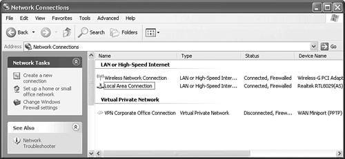
When you are done, the profile will automatically start up, where you either can change the properties of the connection profile or connect to the VPN gateway via your profile. Once you have added your profile, you can see it in the Network Connections window under the Virtual Private Network section, as shown in Figure 13-11.
Figure 13-11. Network Connections Window
Note
The above steps are based on using Windows XP Professional, so there might be some slight differences with other Windows operating systems.
Connection Properties
Once you've added the connection profile, you'll need to modify its properties before using it. To do this, from the Network Connections window, right-click the VPN connection profile you've added and click Properties.
General Tab
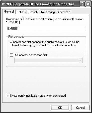
You'll see the window shown in Figure 13-12, with the General tab in the foreground. From this tab you can change the IP address of the VPN gateway (at the top of the window), specify a dialup profile to use to connect to the ISP, and then use the VPN profile to connect to the VPN gateway (in the middle of the window), and allow a PC icon to display in the taskbar when a VPN connection is up (at the bottom of the window).
Figure 13-12. Connection Properties Window: General Tab
Options Tab
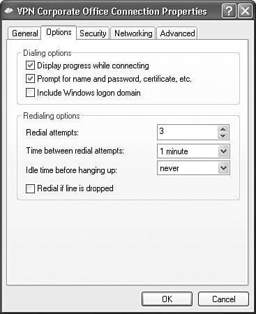
Clicking the Options tab takes you to the window shown in Figure 13-13. At the top are Dialing Options: you can have the connection profile manager display the status of the connection while the connection attempt is made, have the connection profile manager always prompt for a username and password (don't use the saved one), and include the Windows domain name in the login credentials. In the middle of the window are Redialing options, which specify the actions to take when a VPN connection is not set up successfully.
Figure 13-13. Connection Properties Window: Options Tab
Security Tab
Clicking the Security tab takes you to the window shown in Figure 13-14. If you use the Typical settings, you can require the use of a secured password (some form of CHAP) or use a smartcard for authentication, use the Windows logon name and password (including any domain name) for authentication, and require data encryption between the client and gateway (if this is selected and encryption can't be successfully negotiated, the connection is dropped by the client).
Figure 13-14. Connection Properties Window: Security Tab
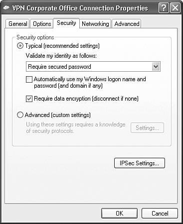
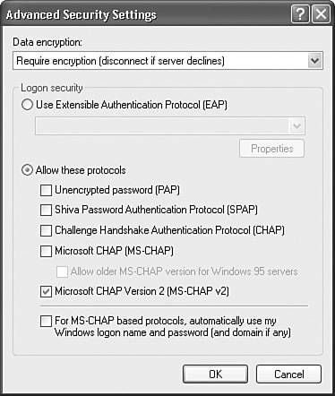
If you click the Advanced (custom settings) radio button and click the Settings button (grayed-out in Figure 13-14), you can customize the settings: This is the option you need to choose when connecting to a Cisco VPN 3000 concentrator! This screen is shown in Figure 13-15. Select the data encryption option, leave it as "Require Encryption," because this is the most secure, and change the authentication method to what you've configured on the VPN gateway; in this example, I've chosen only MSCHAPv2; however, most customers will use EAP because EAP supports the most flexible number of authentication choices. Click the OK button to close the window.
Figure 13-15. Advanced Security Settings Window
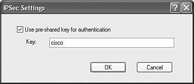
At the bottom of the window in Figure 13-14 is the IPsec Settings button. Clicking this takes you to the window in Figure 13-16. Here you can enter the pre-shared key that will be used during device authentication in ISAKMP/IKE Phase 1. This can be used to override the local policy configuration, which probably is necessary if you need to create multiple connection profiles for multiple VPN gateways. Click the OK button to accept your changes and return to the window in Figure 13-14.
Figure 13-16. IPsec Pre-shared Key Configuration
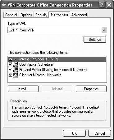
Network Tab
Clicking the Network tab in Figure 13-14 takes you to the window shown in Figure 13-17. At the top of the window you can choose the type of VPN: "Automatic," "PPTP VPN," or "L2TP IPsec VPN." If your client doesn't support L2TP/IPsec, you won't see the latter option, but just plain "L2TP VPN." I recommend that you choose L2TP/IPsec manually, because it is more secure than PPTP.
Figure 13-17. Connection Properties Window: Networking Tab
Caution
If you have set the ProhibitIpSec parameter in the registry to 1, then choosing "L2TP IPsec VPN" is misleading, because this selection causes your connection profile to use L2TP without IPsec!
In Figure 13-17, clicking the Settings button below the type selection will pop up a PPP Settings window where you can:
- Enable LCP extensions enabled by default; LCP extensions are used by PPP to establish a session
- Enable software compression enabled by default; for LAN connections, like cable modem or PPP over Ethernet, disable this!
- Negotiate multi-link for single link connections disabled by default
Tip
Be sure that for LAN connections, you disable the Enable software compression option in the PPP Settings window; otherwise, your VPN throughput will suffer dramatically.
Below the types of VPN selections in Figure 13-17 is the list of the networking protocols and features enabled. You might want to configure your TCP/IP settings for the VPN connection by double-clicking the "Internet Protocol (TCP/IP)." The screen you see here is the same you would see if configuring a physical adapter. Be sure the Obtain an IP address automatically radio box is selected. Unfortunately, split DNS is not supported, so if you need to resolve DNS names located at the corporate office where these devices are using private addresses, then you must ensure that the Obtain DNS server address automatically radio box is also selected.
At the bottom of this same window is an Advanced button; clicking this pulls up the Advanced TCP/IP Settings window where three tabs are shown:
- General allows you to define routing options.
- DNS allows you to define DNS options, like appending name suffixes together, dynamic DNS, and so on.
- WINS allows you to add multiple WINS server addresses, including the prioritization of their usage, enable LMHOSTS lookup, and enable or disable NetBIOS over TCP/IP (enabled by default).
The only tab I'll talk about is the General tab, because this can create connectivity problems if not properly configured (the other two tabs are self-explanatory). There is only one option in this window: a check box for Use default gateway on remote network, which specifies the VPN gateway as the default route when a VPN connection is established, overriding any other default route on your PC. This is enabled by default.
When you choose this option, the VPN default route is used for all traffic sent by your computer. In other words, all traffic is sent to the VPN gateway. Unfortunately, split-tunneling is not supported by Microsoft's client (if you used the Cisco VPN Client, then you wouldn't have this problem because you could enable split-tunneling). There are two ways you can solve your routing issues in this instance:
- Use the default route feature, causing all of your computer's traffic to be routed first to the VPN gateway, and then to its destination. In many instances this can place an undue burden on the VPN gateway. Example 13-1 shows the routing table of a computer with this option enabled. As you can see from this example, the internally assigned address from the VPN gateway is the default route, which means that all traffic must be sent across the VPN tunnel before going to its ultimate destination. The problem with this approach is that all trafficcorporate office and Internetmust be sent to the VPN gateway. The only exception to this is local LAN traffic.
Example 13-1. IP Configuration and Routing
C:> ipconfig Windows IP Configuration Ethernet adapter Local Area Network: Connection-specific DNS Suffix . : IP Address. . . . . . . . . . . .: 192.1.1.67 Subnet Mask . . . . . . . . . . .: 255.255.255.0 Default Gateway . . . . . . . . .: PPP adapter VPN Corporate Office Connection: Connection-specific DNS Suffix . : IP Address. . . . . . . . . . . .: 192.168.101.120 Subnet Mask . . . . . . . . . . .: 255.255.255.0 Default Gateway . . . . . . . . .: 192.168.101.120 C:> route print
 output omitted
images/U2192.jpg border=0> Active Routes: Network Dest Netmask Gateway Interface Metric 0.0.0.0 0.0.0.0 192.168.101.120 192.168.101.120 1 192.1.1.0 255.255.255.0 192.1.1.67 192.1.1.67 30
output omitted - Disable the default route feature. Upon doing this, your computer no longer will know how to reach destinations across the L2TP/IPsec tunnel at the corporate office.
Note
In Windows XP, the L2TP/IPsec client does support split-tunneling population via DHCP: this was a new feature added in VPN 3000 Concentrator's Version 4.0 software. Even though it doesn't have the same level of absolute enforcement as the Cisco VPN client, it is available and a more preferable solution than the two above bullet points.
To solve the latter problem in the previous bulleted list, you'll need to create static routes on your computer with the route command. For example, assume that there are two networks at the corporate office your computer needs to access across the L2TP/IPsec connection: 192.168.101.0/24 and 192.168.102.0/24. You'll need to create two static routes. However, for the next-hop address, you'll have to put the VPN gateway assigned address (the internal one), which is dynamically assigned to the client. This causes the computer to route traffic for the specified networks across the VPN connection. For example, if the VPN gateway assigned you an internal address of 192.168.101.120 (determined by using the ipconfig command), your two static routes would be like that shown in Example 13-2:
Example 13-2. Static Route Configuration
C:> route add 192.168.101.0 mask 255.255.255.0 192.168.101.120
C:> route add 192.168.102.0 mask 255.255.255.0 192.168.101.120
The problem with this approach is that because your computer always acquires its address dynamically, each time you establish a VPN connection, you would have to re-enter the static routes manually with the correct internally assigned address. If this creates problems, then configure an internal address on the client statically in the Network Settings for the VPN connection profile on the computer and then, on the concentrator, in the user's group under the PPTP/L2TP tab, check the Use Client Address check box. By using this option, you can create the static routes with the -d option, which makes them persistent routes: they'll stay in the computer's configuration even if you reboot the computer. Using this solution reduces the burden on the computer and VPN gateway because all traffic doesn't have to be protected and forwarded to the gateway. In this example, only 192.168.101.0/24 and 192.168.102.0/24 traffic is protected and forwarded to the VPN gateway.
Note
The above solution is not valid for laptops that will be connected directly to the corporate network sometimes and at other times connected via an L2TP/IPsec session.
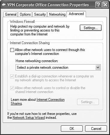
Advanced Tab
Clicking the Advanced tab in Figure 13-14 takes you to the window in Figure 13-18. In the Windows Firewall section at the top (Windows XP SP2 and higher only), clicking the Settings button pulls up the Windows Firewall window, which allows you to configure firewall rules for the VPN connection (if this is necessary). Below the Windows Firewall section is the Internet Connection Sharing section, where you can define sharing properties for allowing other network users to use your VPN session.
Figure 13-18. Connection Properties Window: Advanced Tab
Tip
If a corporate office network administrator needs to access your machine remotely for troubleshooting purposes, click the Exceptions tab in the Windows Firewall window and check the Remote Desktop check box.
Part I: VPNs
Overview of VPNs
- Overview of VPNs
- Traffic Issues
- VPN Definition
- VPN Components
- VPN Designs
- VPN Implementations
- VPNs: Choosing a Solution
- Summary
VPN Technologies
IPsec
PPTP and L2TP
SSL VPNs
Part II: Concentrators
Concentrator Product Information
- Concentrator Product Information
- Concentrator Models
- Concentrator Modules
- Concentrator Features
- Introduction to Accessing a Concentrator
- Summary
Concentrator Remote Access Connections with IPsec
- Concentrator Remote Access Connections with IPsec
- Controlling Remote Access Sessions to the Concentrator
- IPsec Remote Access
- Network Access Control (NAC) for IPsec and L2TP/IPsec Users
- Summary
Concentrator Remote Access Connections with PPTP, L2TP, and WebVPN
- Concentrator Remote Access Connections with PPTP, L2TP, and WebVPN
- PPTP and L2TP Remote Access
- WebVPN Remote Access
- Summary
Concentrator Site-to-Site Connections
- Concentrator Site-to-Site Connections
- L2L Connectivity Example
- ISAKMP/IKE Phase 1 Preparation
- Adding Site-to-Site Connections
- Address Translation and L2L Sessions
- Summary
Concentrator Management
- Concentrator Management
- Bandwidth Management
- Routing on the Concentrator
- Chassis Redundancy
- Administration Screens
- Summary
Verifying and Troubleshooting Concentrator Connections
- Verifying and Troubleshooting Concentrator Connections
- Concentrator Tools
- Troubleshooting Problems
- Summary
Part III: Clients
Cisco VPN Software Client
- Cisco VPN Software Client
- Cisco VPN Client Overview
- Cisco VPN Client Interface
- IPsec Connections
- VPN Client GUI Options
- VPN Client Software Updates
- VPN Client Troubleshooting
- Summary
Windows Software Client
- Windows Software Client
- Windows Client
- Configuring the Windows VPN Client
- Configuring the VPN 3000 Concentrator
- Microsoft Client Connections
- Troubleshooting VPN Connections
- Summary
3002 Hardware Client
- 3002 Hardware Client
- Overview of the 3002 Hardware Client
- Initial Access to the 3002
- Authentication and Connection Options
- Connection Modes
- Administrative Tasks
- Summary
Part IV: IOS Routers
Router Product Information
Router ISAKMP/IKE Phase 1 Connectivity
- Router ISAKMP/IKE Phase 1 Connectivity
- IPsec Preparation
- ISAKMP/IKE Phase 1 Policies
- ISAKMP/IKE Phase 1 Device Authentication
- Monitoring and Managing Management Connections
- Routers as Certificate Authorities
- Summary
Router Site-to-Site Connections
- Router Site-to-Site Connections
- ISAKMP/IKE Phase 2 Configuration
- Viewing and Managing Connections
- Issues with Site-to-Site Connections
- Summary
Router Remote Access Connections
- Router Remote Access Connections
- Easy VPN Server
- Easy VPN Remote
- IPsec Remote Access and L2L Sessions on the Same Router
- WebVPN
- Summary
Troubleshooting Router Connections
- Troubleshooting Router Connections
- ISAKMP/IKE Phase 1 Connections
- ISAKMP/IKE Phase 2 Connections
- New IPsec Troubleshooting Features
- Fragmentation Problems
- Summary
Part V: PIX Firewalls
PIX and ASA Product Information
- PIX and ASA Product Information
- PIX Deployment Scenarios
- PIX and ASA Feature and Product Overview
- Summary
PIX and ASA Site-to-Site Connections
- PIX and ASA Site-to-Site Connections
- ISAKMP/IKE Phase 1 Management Connection
- ISAKMP/IKE Phase 2 Data Connections
- L2L Connection Examples
- Summary
PIX and ASA Remote Access Connections
- PIX and ASA Remote Access Connections
- Easy VPN Server Support for 6.x
- Easy VPN Remote Support for 6.x
- Easy VPN Server Support for 7.0
- Summary
Troubleshooting PIX and ASA Connections
- Troubleshooting PIX and ASA Connections
- ISAKMP/IKE Phase 1 Connections
- ISAKMP/IKE Phase 2 Connections
- Summary
Part VI: Case Study
Case Study
Index
EAN: 2147483647
Pages: 178
