Connection Modes
The Cisco hardware clients, including the 3002, support two connection modes to an Easy VPN Server: client mode and network extension mode. Both of these modes were discussed in Chapter 3, "IPsec." The following sections will discuss the two modes and how to enable them.
Client Mode
The top part of Figure 3-3 from Chapter 3 shows an example of client mode. As a quick review, in client mode, the Easy VPN Server assigns the remote access hardware client a single, internal IP address. For devices behind the hardware client to access the corporate site across the tunnel, the hardware client performs PAT on the inside packets to the internal IP address assigned to it by the Server. From the corporate office's perspective, it looks as if a single device is connected to the network, when in reality, it could be a few hundred (with the 3002, the limit is 253 devices off of the private interface).
Note
The default behavior of the 3002 is to use client mode; in other words, it's already set up to PAT addresses going across the tunnel.
Network Extension Mode
The bottom part of Figure 3-3 shows an example of network extension mode. Network extension mode simulates an L2L tunnel. Please note that it is not, however, an L2L session. The hardware client, like the 3002, is still a client and connects to the Easy VPN Server, where in ISAKMP/IKE Phase 1, XAUTH and IKE Mode Config occur (which is not the case with a true L2L tunnel session). The main difference is that the remote access client will share the network number and subnet mask of its private interface, during ISAKMP/IKE Phase 1, with the Server via reverse route injection (RRI).
The main limitation of client mode is that the central office cannot initiate a connection to a device behind the hardware client because PAT is being used. With network extension mode, no address translation occurs; typically, the network number off of the private interface of the hardware client is a unique subnet of a network used from the corporate office. Using this mode, a device at the central office can access a device at the SOHO easily. This might be necessary for management, file-sharing, or VoIP purposes.
Note
In network extension mode, only the directly connected network of the private interface is advertised to the Easy VPN Server. If you had more than one network behind the hardware client, these additional networks would be unknown to the VPN gateway. Therefore, if you had multiple subnets behind your hardware client, you would have to use client mode or use a different VPN device that supported L2L sessions.
The configuration of network extension mode involves three configuration steps: two on the 3002 and one on the Easy VPN Server. The following sections will discuss the setup of these items on both the 3002 and VPN 3000 concentrators.
3002 Network Extension Mode Configuration
By default, the 3002 uses client mode for its connection to an Easy VPN Server. There are two configuration steps you need to perform on the 3002 to enable network extension mode:
|
Step 1. |
Change the IP address on the private interface to something different than 192.168.10.1. |
|
Step 2. |
Disable PAT. |
Either you can perform these steps from Quick Configuration mode (go to Configuration > Quick Configuration), which I discussed in the "Quick Configuration" section earlier in the chapter, or do them from the main menu Configuration section.
Within Quick Configuration, you need to click to the Private Intf hyperlink first and change the private interface IP address to something different from 192.168.10.1 (Figures 14-6 and 14-7) and then click the PAT hyperlink and select the No, use Network Extension mode option (Figure 14-10 shows an example where the IP address wasn't changed from 192.168.10.1). Click the Done hyperlink when you're finished with Quick Configuration mode.
If you are going to do it using the latter method, to perform the first step, go to Configuration > Interfaces and click the hyperlink labeled Ethernet 1 (Private). Change the IP address and, possibly, subnet mask, and click the Apply button. Once you have done this, then go to Configuration > Policy Management > Traffic Management > PAT > Enable and uncheck the check box labeled PAT Enabled. Click the Apply button to accept your change.
Concentrator Network Extension Mode Configuration
The last step you must perform is on the Easy VPN Server, such as a VPN 3000 concentrator. On a concentrator, this is performed under the group configuration (Configuration > User Management > Groups). Select the group name and click the Modify button; then click the HW Client tab. If you refer back to Figure 14-17, the last option under this tab is Allow Network Extension Mode; click the check box for this option and click the Apply button at the bottom. Now, if any hardware client in the group is set up for network extension mode, the connection mode will be allowed.
Note
It is important to point out that if you don't enable network extension mode on the VPN 3000 concentrator, the 3002 can only use client mode; and if you have disabled PAT, then devices behind the 3002's private interface won't be able to access the central site via the IPsec tunnel.
Network Extension Mode Verification
There are a few ways that you can verify if your IPsec tunnel to the VPN 3000 concentrator is using network extension mode. First, on the 3002, go to Monitoring > System Status. Examine Figure 14-16. If you see the line Assigned IP Address and an internal IP address assigned by the Easy VPN Server, then you're operating in client mode. You won't see this line when operating in network extension mode.
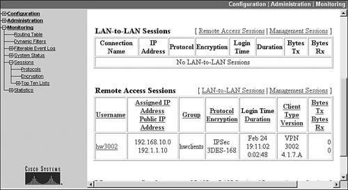
On the VPN 3000 concentrator, go to Monitoring > Sessions and scroll down to the Remote Access Sessions section, like that shown in Figure 14-23. Examine the Assigned IP Address Public IP Address column. With a session using client mode, you'll see the assigned IP address from the address pool the concentrator is using (or from an AAA or DHCP server if the address pool is defined externally); with network extension mode, you'll see the network number of the hardware client's private interface. In Figure 14-23, this is 192.168.10.0.
Figure 14-23. Verifying Network Extension Mode on a Concentrator
If there is a problem connecting using network extension mode, the 3002's Event Log is not too illuminating about this particular problem; however, if you look at the concentrator's Event Log, you'll see something like that shown in Example 14-2. In this example, a 3002 with an address of 192.1.1.10 is trying to make a connection. Event 823 indicates that device and XAUTH authentication are successful. Event 826, however, displays that the group the 3002 belongs to is not configured for network extension mode, but the 3002 is trying to use it (PAT is disabled). Given this, the ISAKMP/IKE Phase 1 connection will fail.
Example 14-2. Network Extension Mode Misconfiguration
817 02/26/2005 15:49:05.310 SEV=5 IKEDBG/64 RPT=45 192.1.1.10
IKE Peer included IKE fragmentation capability flags:
Main Mode: True
Aggressive Mode: True


819 02/26/2005 15:49:05.800 SEV=5 IKE/172 RPT=45 192.1.1.10
Group [hwclients]
Automatic NAT Detection Status:
 Remote end is NOT behind a NAT device
 This end is NOT behind a NAT device


823 02/26/2005 15:49:06.120 SEV=4 IKE/52 RPT=43 192.1.1.10
Group [hwclients] User [hw3002]
User (hw3002) authenticated.
824 02/26/2005 15:49:06.150 SEV=5 IKE/184 RPT=43 192.1.1.10
Group [hwclients] User [hw3002]
Client Type: VPN 3002
Client Application Version: 4.1.7.A


826 02/26/2005 15:49:06.150 SEV=4 IKE/174 RPT=34 192.1.1.10
Group [hwclients] User [hw3002]
Hardware Client connection rejected!
Network Extension Mode is not allowed for this group!
If the negotiation of network extension mode is successful, instead of seeing event 826 in Example 14-2, you would see the event in Example 14-3. In this example, you can see the client type and version. Of course, this message has nothing to do with network extension mode, but this is what you will see if policies are successfully negotiated.
Example 14-3. Successful Negotiation of Network Extension Mode
1679 02/26/2005 15:54:59.910 SEV=5 IKE/184 RPT=114 192.1.1.10
Group [hwclients] User [hw3002]
Client Type: VPN 3002
Client Application Version: 4.1.7.A
Note
To use network extension mode, the 3002's IP address cannot be 192.168.10.1. However, this does not mean you have to change the network addressing scheme; you can easily change the IP address to 192.168.10.2, which would fulfill the address change requirements. In Figure 14-23, the 3002 has this address on its private interface. However, each hardware client needs a unique network number for its private interface.
Routing and Reverse Route Injection
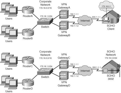
One of the problems with remote access clients connecting to a central office using client mode or network extension mode is that if there are two Easy VPN Servers, like that shown in Figure 14-24, then which of the Servers should central office devices use to reach the client? This is especially problematic if you're using VCA load balancing or VRRP redundancy. Which of the Servers is the client connected to? And even if you would find out this information, it might change based on the next session the client builds to the central office.
Figure 14-24. Remote Access Clients, Central Site Redundancy, and Routing Issues
Routing Features
The only way to deal with this reachability problem is to:
- Use a dynamic routing protocol on the VPN gateways and have the gateways advertise this information to the central site layer-3 devices; this is necessary if an AAA RADIUS or DHCP server will be assigning addresses to the clients using client mode or the client is using network extension mode
- Use static routing on the layer-3 devices to point to the correct concentrator; this will only work for client mode connections where each concentrator has its own pool of addresses it assigns to clients
Assuming you're using the first bullet point as your solution. No matter what Easy VPN Server a remote access client is connected to, the Servers will propagate the updated routing information to the internal layer-3 devices so that corporate office devices can reach the remote access clients.
One of the interesting things about this process is that remote access clients don't advertise routing information via a routing protocol. Instead, either the internally assigned IP address (client mode) or the network number of the private interface (network extension mode) is shared with the Easy VPN Server. Only the Server understands this and associates these numbers with the IPsec SAsthis information doesn't even appear in the Server's routing table.
However, Cisco Easy VPN Servers support a process called reverse route injection (RRI) to place the client's routing information in the Easy VPN Server's local routing table as a static route and allow the static routes to be redistributed via a local routing protocol out of the Server's other interfaces. With the VPN 3000 concentrators, the static routes can be redistributed using RIPv1, RIPv2, or OSPF.
RRI Configuration
Configuring RRI is an Easy VPN Server configuration task: the remote access clients have no clue, nor do they care, that this process is occurring. On the VPN 3000 concentrators, this configuration is done in two steps:
|
Step 1. |
Enable RRI. |
|
Step 2. |
Configure the dynamic routing protocol. |
I already discussed Step 2 in Chapter 10, "Concentrator Management." You need to configure the routing protocol, if it happens to be OSPF, and enable the routing protocol on the private, and possibly external, interface of the concentrator. In this section, I'll only discuss the first step: Enabling RRI.
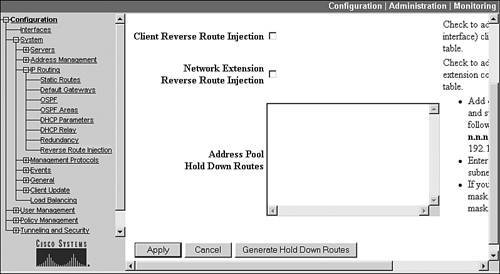
To enable RRI on your VPN 3000 concentrator, go to the Configuration > System > IP Routing > Reverse Route Injection screen, shown in Figure 14-25. If you use both types, select both check boxes: Client Reverse Route Injection and Network Extension Reverse Route Injection. If you don't select an RRI type, that type doesn't show up as a static route in the concentrator's local routing table and thus can't be redistributed to other central office devices. The Address Pool Hold Down Routes allows you to list routes the concentrator will always advertise as reachable: this option can be used if a client always connects to the same concentrator no matter what, and you always want the concentrator to advertise the route, especially with RIP, to reduce convergence time when an IPsec tunnel is being built or rebuilt by the client. Once you've configured the information on the screen, click the Apply button to save your changes.
Figure 14-25. RRI Configuration on a Concentrator
Once you have configured RRI, you can verify that it's working by examining the concentrator's local routing table: Monitoring > Routing Table. For clients using network extension mode, you should see their private interface network numbers show up as static routes in the routing table; for clients using client mode, you should see their internal IP addresses show up as static host routes.
Part I: VPNs
Overview of VPNs
- Overview of VPNs
- Traffic Issues
- VPN Definition
- VPN Components
- VPN Designs
- VPN Implementations
- VPNs: Choosing a Solution
- Summary
VPN Technologies
IPsec
PPTP and L2TP
SSL VPNs
Part II: Concentrators
Concentrator Product Information
- Concentrator Product Information
- Concentrator Models
- Concentrator Modules
- Concentrator Features
- Introduction to Accessing a Concentrator
- Summary
Concentrator Remote Access Connections with IPsec
- Concentrator Remote Access Connections with IPsec
- Controlling Remote Access Sessions to the Concentrator
- IPsec Remote Access
- Network Access Control (NAC) for IPsec and L2TP/IPsec Users
- Summary
Concentrator Remote Access Connections with PPTP, L2TP, and WebVPN
- Concentrator Remote Access Connections with PPTP, L2TP, and WebVPN
- PPTP and L2TP Remote Access
- WebVPN Remote Access
- Summary
Concentrator Site-to-Site Connections
- Concentrator Site-to-Site Connections
- L2L Connectivity Example
- ISAKMP/IKE Phase 1 Preparation
- Adding Site-to-Site Connections
- Address Translation and L2L Sessions
- Summary
Concentrator Management
- Concentrator Management
- Bandwidth Management
- Routing on the Concentrator
- Chassis Redundancy
- Administration Screens
- Summary
Verifying and Troubleshooting Concentrator Connections
- Verifying and Troubleshooting Concentrator Connections
- Concentrator Tools
- Troubleshooting Problems
- Summary
Part III: Clients
Cisco VPN Software Client
- Cisco VPN Software Client
- Cisco VPN Client Overview
- Cisco VPN Client Interface
- IPsec Connections
- VPN Client GUI Options
- VPN Client Software Updates
- VPN Client Troubleshooting
- Summary
Windows Software Client
- Windows Software Client
- Windows Client
- Configuring the Windows VPN Client
- Configuring the VPN 3000 Concentrator
- Microsoft Client Connections
- Troubleshooting VPN Connections
- Summary
3002 Hardware Client
- 3002 Hardware Client
- Overview of the 3002 Hardware Client
- Initial Access to the 3002
- Authentication and Connection Options
- Connection Modes
- Administrative Tasks
- Summary
Part IV: IOS Routers
Router Product Information
Router ISAKMP/IKE Phase 1 Connectivity
- Router ISAKMP/IKE Phase 1 Connectivity
- IPsec Preparation
- ISAKMP/IKE Phase 1 Policies
- ISAKMP/IKE Phase 1 Device Authentication
- Monitoring and Managing Management Connections
- Routers as Certificate Authorities
- Summary
Router Site-to-Site Connections
- Router Site-to-Site Connections
- ISAKMP/IKE Phase 2 Configuration
- Viewing and Managing Connections
- Issues with Site-to-Site Connections
- Summary
Router Remote Access Connections
- Router Remote Access Connections
- Easy VPN Server
- Easy VPN Remote
- IPsec Remote Access and L2L Sessions on the Same Router
- WebVPN
- Summary
Troubleshooting Router Connections
- Troubleshooting Router Connections
- ISAKMP/IKE Phase 1 Connections
- ISAKMP/IKE Phase 2 Connections
- New IPsec Troubleshooting Features
- Fragmentation Problems
- Summary
Part V: PIX Firewalls
PIX and ASA Product Information
- PIX and ASA Product Information
- PIX Deployment Scenarios
- PIX and ASA Feature and Product Overview
- Summary
PIX and ASA Site-to-Site Connections
- PIX and ASA Site-to-Site Connections
- ISAKMP/IKE Phase 1 Management Connection
- ISAKMP/IKE Phase 2 Data Connections
- L2L Connection Examples
- Summary
PIX and ASA Remote Access Connections
- PIX and ASA Remote Access Connections
- Easy VPN Server Support for 6.x
- Easy VPN Remote Support for 6.x
- Easy VPN Server Support for 7.0
- Summary
Troubleshooting PIX and ASA Connections
- Troubleshooting PIX and ASA Connections
- ISAKMP/IKE Phase 1 Connections
- ISAKMP/IKE Phase 2 Connections
- Summary
Part VI: Case Study
Case Study
Index
EAN: 2147483647
Pages: 178
