Chassis Redundancy
The concentrators support two general types of redundancy: intra- and inter-chassis redundancy. Intra-chassis redundancy is available on the 3015 concentrators and higher, where dual power supplies and redundant SEP cards are supported. All of the Cisco concentrators, however, support inter-chassis redundancy through one of two solutions:
- Virtual Router Redundancy Protocol (VRRP)
- Virtual Cluster Agent (VCA), sometimes referred to as Remote Access Load Balancing
Both are mutually exclusive. You can use one or the other; both have advantages and disadvantages. For example, VRRP, because it is a standard, can be used to provide redundancy using concentrator and nonconcentrator products (such as Cisco routers); however, VRRP does not support load balancingonly redundancy. VCA, on the other hand, allows for load balancing of incoming remote access sessions; however, VCA is supported only by the VPN 3000 concentrators and the ASA security appliances.
The following two sections will discuss how these inter-chassis redundancy features are implemented on the concentrators.
VRRP
VRRP provides inter-chassis redundancy and is an open standard; even Cisco routers support it. VRRP is typically used to provide default gateway redundancy; however, it can also be used to provide redundancy for VPN connectivity.
With VRRP, an election process is used to elect a master device responsible for handling traffic, including VPN traffic. A virtual address is then assigned by the master, and remote devices connect to this virtual address. The virtual addresses are most commonly the configured IP addresses on the interfaces of the master, but can be a virtual address. The master will process packets sent to the virtual address. One or more backup VRRP peers monitor the status of the master; if the master fails, one of the backups will be promoted to the master role and will begin processing packets sent to the virtual address.
VRRP Example
Figure 10-10 illustrates how VRRP works. In this example, there are two concentrators at the corporate site. One VRRP group is used off of each interface: Group 1. ConcentratorA is the master for each group (you can influence the election process by changing the priority of the master). Note that the virtual addresses used are those of the master concentrator.
Figure 10-10. VRRP Example
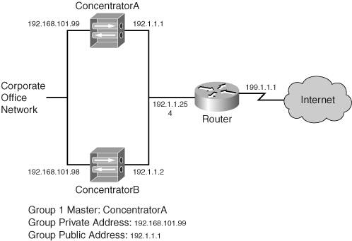
All concentrators in the group periodically send hellos. The default polling period is once every three seconds, but this can be reduced to one second; if three hellos are missed from the master, the backup will promote itself to the master role. Based on the hello interval, this can range from 310 seconds.
When the master fails, all VPN sessions handled by the master also fail. The backup concentrator will take over only when it stops receiving the master's hello off of all interfaces enabled for VRRPa single interface failover on the master will not cause a failover.
Tip
To ensure that inadvertent cutovers don't take place because of spanning tree (where the concentrators are connected to switches), configure your switches using the PortFast feature for the ports the concentrators are connected to.
L2L sessions will be rebuilt to the new master automatically when a cutover takes place; however, remote access sessions will have to be rebuilt by the client user unless auto-initiation for software clients or network extension mode for hardware clients is usedthis is also true of the VCA feature.
Note
In the example in Figure 10-10, you would probably have dual routers connected to the Internet for redundancy and set up HSRP or VRRP between them. Then you would create a default route on the concentrators and point them to the virtual address. The configuration of this is beyond the scope of this book; however, I discuss this type of configuration, from a security perspective, in my book Cisco Router Firewall Security from Cisco Press.
VRRP Configuration
To set up VRRP, go to the Configuration > System > IP Routing > Redundancy screen, as shown in Figure 10-11. To enable VRRP, click the Enable VRRP check box. The Group ID parameter assigns a number to the VRRP groupthis needs to be the same on all the concentrators. Because it is rare that you would have more than one group on a LAN, you can probably accept the default value, which is 1; however, the number can range from 1255.
Figure 10-11. VRRP Configuration
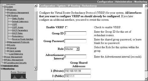
To provide additional security, you can password-authenticate VRRP messages by entering a password in the Group Password parameter; however, this value is sent across the wire in clear text, so it doesn't provide that much additional security! The Role drop-down selector allows you to choose the role the concentrator will play: "Master" and "Backup 1" through "Backup 5." The hello interval defaults to one second, but can be changed with the Advertisement Interval parameter; making this a higher number slows down a failover.
At the bottom of the screen are the Group Shared Addresses. These are the "virtual" addresses other devices will use to reach the concentrator. These addresses default to the IP addresses on the concentrator's interfaces; however, on the backup concentrators, you must change these to match that of the master's IP addresses on its respective interfaces. Please note that you don't have to use the physical IP addresses of the master for the virtual addressesyou can use an unused address off the concentrator's specified interface (this is a common practice).
If you have filters on the concentrator interfaces, like the public interface, you'll need to make sure you have VRRP rules on the interface filter(s) to allow the VRRP messages to be generated on the interface and received on the interface (outbound and inbound, respectively). Also, to verify that VRRP is functioning correctly between VRRP devices, go to the Monitoring > Statistics > VRRP screen and examine its output. You should be able to see which role the concentrator is playing (for example, master) and you should see the Advertisements Received value incrementing when you refresh the screen periodically. If you see any of the error values increasing, you have a configuration problem.
Note
Because only one VRRP group can be configured on the concentrators, only one member will handle traffic sent to the virtual addresses. This means that other members will monitor the master only passively and will not pass VPN traffic. Therefore, a better solution would be to use routers, which support multiple VRRP (or HSRP) groups, which allow redundancy while at the same time allowing the use of one router in each group. This solution allows you to load balance on the router; however, the disadvantage is that concentrators are more scalable than routers when it comes to handling large numbers of remote access sessions.
VRRP Configuration Synchronization
When using VRRP for redundancy, most of the configuration of the master must be identical on the backup peers. For example, if you have remote access users connecting to you, the group and user configurations need to be replicated between the concentrators. This would be true of other VPN configurations on your concentrator. The hard way of accomplishing this would be to configure each concentrator manually and separately.
Unfortunately, there is no automatic configuration replication between concentrators. Therefore, I discuss the next-best method of accomplishing this. Many of the things discussed here will be discussed in more depth later in the "File Management" section.
The first thing you'll do is save the master's configuration. Go to the Administration > File Management screen on the master concentrator, which is shown later in Figure 10-15. For the file called "CONFIG," click its View hyperlink, displaying the current concentrator configuration. Select and copy the entire configuration and paste it into a text editor such as Windows Notepad.
In the text editor, find the following three sections: [ip 1], [ip 2], and [ip 3], as shown in Example 10-1:
Example 10-1. Master Concentrator Configuration File: IP Addressing
output omitted
images/U2192.jpg border=0> [ip 1] enable=1 address=192.168.101.99 mask=255.255.255.0
Please note that for a 3005, you'll have only the first two sections because this concentrator only has two interfaces. These are the IP addresses on the master's interfaces. For the backup concentrator, these will need to be changed to represent what the backup concentrator will use. In the example in Figure 10-10, these would be 192.168.101.98 for "ip 1" and 192.1.1.2 for "ip 2".
Next, look for the [vrrpif 1.1], [vrrpif 2.1], and [vrrpif 1.1] sections in the master's configuration, as shown in Example 10-2:
Example 10-2. Master Concentrator Configuration File: VRRP
[vrrpif 1.1] rowstatus=1 state=1 priority=255
In each vrrpif section, change the priority parameter from 255 to something smaller, such as 254. Save the file as a text file (.txt extension).
Once you have completed these steps, you'll use this configuration on the backup concentrator in the VRRP group. In the example in Figure 10-10, you would log in to the backup concentrator and go to Administration > File Management. Click the File Upload hyperlink. For the File on the VPN 3000 Concentrator parameter, enter CONFIG.BAK. For the Local File parameter, use the Browse button to find the text file you just created. Then click the Upload button to upload this configuration file of the backup concentrator to Flash memory.
At this point, the backup concentrator isn't using this configuration. To use this modified configuration, you would need to click the Swap Configuration Files hyperlink on the Administration > File Management screen. Click the OK button to swap the CONFIG.BAK file with the CONFIG file; this will switch the two configuration files. Then reboot the concentrator by going to the reboot screen: Administration > System Reboot. You can then choose the following options:
- Reboot
- Reboot without saving the active configuration
- Now
Then click the Apply button. When the backup concentrator reboots, the file you changed will be loaded on the backup concentrator. Please note that this synchronization process also applies if you will be using VCA for redundancy, which is discussed in the next section.
Note
Please note that other parameters might need to be changed on the backup concentrator depending on other features you have enabled in your concentrator configuration.
Also, you can use this handy shortcut to move other types of configurations between concentrators, such as remote access groups and their parameters.
VCA
VCA is a VPN 3000 concentrator and ASA security appliance feature that provides redundancy for remote access sessions. This feature was first introduced in 3.0 on the concentrator. VCA is part of the concentrator's operating system and requires no additional software. The next couple of sections will discuss this feature.
Note
VCA and VRRP are mutually exclusive: you can only use one of these redundancy features on a concentrator.
VCA Operation
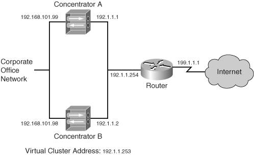
Figure 10-12 illustrates how VCA works. There are three basic steps in the operation of VCA:
|
1. |
Elect a master |
|
2. |
Load-balance remote access sessions |
|
3. |
Verify the operation of the master |
Figure 10-12. VCA Example
Elect a Master
With VCA, the concentrators form a cluster, with one member of the cluster performing the function of a master. The master is elected by using the one with the highest VCA priority. Each concentrator has a default priority based on its hardware model: the more powerful the concentrator, the higher the priority. The election process happens at the time the concentrators boot up and their interfaces become active. If all concentrators boot up at the same time, and they have the same priority, the one with the lowest IP address (on the public interface) is chosen as the master.
Once the master is elected, it maintains this role even if another concentrator comes online with a higher priority. Unlike other redundancy protocols such as HSRP, VCA doesn't support a preemption process. The only time a master is elected is upon the initial bootup of the concentrators or when the current master fails. For example, in Figure 10-12, if both concentrators were the same model, like 3030s, and if both booted up at the same time, ConcentratorA would be elected as master because it has a lower IP address.
Load-Balance Remote Access Sessions
The cluster itself is represented by a logical address, commonly referred to as a virtual address. This address must be an unused address associated with the LAN segment the concentrators' public interfaces are connected to. For example, in Figure 10-12, the public interface LAN segment is 192.1.1.0/24 and three addresses already are used. For this example, 192.1.1.253 has been chosen as the virtual address.
All remote access clients must use the virtual address when making a connection to the cluster. The master will process traffic sent to this address; so for the session from the client, the master will answer the session request; however, the master will not, by default, terminate the session on itself. Instead, the master looks at the current loads of the concentrators in the cluster and chooses the one with the least load.
Remember that load is not based on the amount of traffic going through the concentrator, but on the number of current sessions terminated on the concentrator. Load is calculated by taking the current number of sessions on the concentrator and dividing that number by the total number of sessions supported by the concentrator. This ensures that higher-end concentrators handle more sessions than lower-end ones, which makes sense. For example, if you had a 3005 and 3080 in a cluster, for every one connection the 3005 would handle, the 3080 would handle 100 or 50, depending on the version of software on the 3005. The current session information is periodically shared with the master.
Note
The number of sessions supported on a concentrator is tunable; you can make it smaller. You might want to do this in environments where you want a smaller concentrator to handle more sessions than it normally would in a cluster.
The master then sends a redirection message to the remote access client requesting the session, where the message contains the public interface IP address of the concentrator that will handle the session (which could be the master itself). Only Cisco VPN clients (software and hardware) and web browsers (WebVPN) understand this redirection message. The remote access client then tears down the initial attempt and starts the session process with the new address.
Note
Only the Cisco Easy VPN IPsec software and hardware clients and WebVPN clients understand the redirection message the master sends. Other VPN implementations, such as PPTP and L2TP/IPsec, still are supported on the concentrators when you are using VCA. However, they can't participate in load balancing. In this instance, you would configure these remote access clients to use the public IP addresses of the concentrators, not the virtual address of the cluster. Also, load balancing of L2L sessions is not supported with VCA. This makes sense, because VCA performs load balancing based on sessions, not amount of traffic, on a concentrator.
Verify the Operation of the Master
Once the master is elected, the backup concentrators in the cluster are responsible for ensuring that the master is still performing its role in addition to handling the setup of any redirected sessions. All the concentrators periodically generate VCA hello/keepalive messages to verify their operation and share their load information. These messages are sent to UDP port 9,023 as multicasts. Therefore, each set of interfaces of the cluster (public, private, and external) must be in the same respective broadcast domains. Optionally, these messages can be encrypted. Plus, if you have filters on the concentrators' interfacesfor example, the public interfaceyou'll need to ensure that you have VCA rules in the interface filter(s) to allow the VCA messages to be generated and received on the interface. VCA filtering rules have already been predefined on the concentrator: you only need to activate them for the interface filter (Configuration > Policy Management > Traffic Management > Filters).
VCA Configuration
To enable and configure VCA, go to Configuration > System > Load Balancing. Figure 10-13 shows the top of this screen and Figure 10-14 the bottom.
Figure 10-13. VCA Configuration: Top
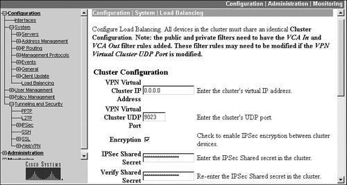
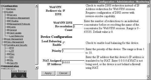
Figure 10-14. VCA Configuration: Bottom
At the top of the screen you need to enter the virtual IP address of the cluster in the VPN Virtual Cluster IP Address parameter. For example, for the concentrators shown in Figure 10-12, you would enter 192.1.1.253 on both members of the cluster. Below this is the VPN Virtual Cluster UDP Port parameter, where the UDP port defaults to 9,023. If you change this on one concentrator in the cluster, you must change it on all the members.
Optionally, you can encrypt the VCA messages between members of the cluster. If you check the Encryption check box, you'll need to enter the key for the encryption process in the IPsec Shared Secret and Verify Shared Secret parameters. This configuration needs to be the same on all peers on the cluster.
In 4.7, two new parameters were added to this screen, shown in Figure 10-14. The WebVPN Redirect via DNS parameter allows the master to redirect connections based on DNS names on the WebVPN client's certificate instead of its IP address. This is disabled by default; if you enable this parameter, you have the option of changing the WebVPN DNS Re-resolution Count parameter; this parameter specifies the maximum number of redirections to a cluster member before the IP address must be revalidated by performing a reverse DNS lookup. The default is 0, which means that no re-resolution takes place: this value can range from 065,535.
To enable VCA, you must click the Load Balancing Enable check box on each member of the cluster. This enables redirection for all supported remote access clients: Cisco VPN Client, Cisco hardware IPsec clients, and WebVPN clients. Optionally, you can change the priority of the concentrator, which affects which member will become the master. The priority can range from 110, where 10 is the highest. Cisco has a default value for the priority based on the concentrator model. Table 10-1 shows the default priorities. Cisco recommends that you leave the priorities at their default values if the concentrators are different models in the cluster, because, based on the default values, the higher-end (and therefore more suitable) concentrator will typically perform the additional tasks of the master.
|
Concentrator |
Priority |
|---|---|
|
3005 |
1 |
|
3015 |
3 |
|
3030 |
5 |
|
3060 |
7 |
|
3080 |
9 |
The last parameter on the screen in Figure 10-14 is the NAT Assigned IP Address parameter. The configuration of this parameter is necessary only if the public IP addresses the cluster members and the virtual address of the cluster are private addresses and are being NATed statically by an address translation device, such as the router in Figure 10-12. If this were true, you would put in the global (publicly visible) IP address that external remote access clients would be using to connect to the cluster in this parameter and still enter the virtual IP address of the cluster (the one associated with the physical LAN segment of the public interface) in the VPN Virtual Cluster IP Address parameter. If the concentrators are using public addresses, then you can leave this parameter configured for "0.0.0.0," which means that no address translation is being performed.
Tip
Remember that, just as with VRRP, the concentrators need similar configurations to support IPsec remote access sessionsin this situation, I would probably use an AAA server to maintain at least the user, and possibly group, information. Therefore, this information wouldn't need to be replicated across the members of the cluster.
VCA Verification
Once you have set up VCA on your cluster members, you'll want to ensure that load balancing is functioning correctly. First, be sure that the members of the cluster can communicate with each other. You can see this information by going to the Monitoring > Statistics > Load Balancing screen. From this screen you can view the following information:
- The role of the concentrator: master or secondary (backup)
- The current load of the concentrator
- The list of VCA peers of this concentrator, and their addresses, role, concentrator model, priority, cluster uptime, and other information
If you have enabled the encryption option for VCA messages, you can see the status of the connections between the concentrators by going to the Monitoring > Sessions screen and looking at the Management Sessions. You should see the IP addresses of the peers in the cluster with a corresponding connection protocol of "VCA/IPsec." If you're not seeing the information I mentioned above in the two Monitoring screens, you probably have a configuration problem on one or more of the concentrators in the cluster. Also, be sure that each concentrator in the cluster can ping other members of the cluster off each interface that is enabled and that you have added the VCA rules to all filters being used on the concentrators.
The virtual IP address cannot be pinged for testing functions. If you need to test connectivity between the remote access client and the cluster, have the client ping the IP address assigned to the master's public interface.
Tip
Because VRRP and VCA are mutually exclusive, I'm often asked which of the two should be used for redundancy. If you have two or more concentrators that primarily are terminating remote access sessions, then I would use VCA, because VCA allows you to use all members in the cluster. Just take care that any L2L sessions do not point to the virtual address of the cluster, but to one of the physical addresses of the concentrators in the cluster; otherwise the L2L session will fail to establish. If you need just temporary redundancy and you have a concentrator and a router, you can use VRRP to provide this function. However, the drawback here is that you must configure the router to support remote access connectivityI might do this just for the most important users. If the setup primarily used L2L sessions on the concentrators, I would use VRRP, because VRRP supports redundancy for both L2L and remote access sessions.
Part I: VPNs
Overview of VPNs
- Overview of VPNs
- Traffic Issues
- VPN Definition
- VPN Components
- VPN Designs
- VPN Implementations
- VPNs: Choosing a Solution
- Summary
VPN Technologies
IPsec
PPTP and L2TP
SSL VPNs
Part II: Concentrators
Concentrator Product Information
- Concentrator Product Information
- Concentrator Models
- Concentrator Modules
- Concentrator Features
- Introduction to Accessing a Concentrator
- Summary
Concentrator Remote Access Connections with IPsec
- Concentrator Remote Access Connections with IPsec
- Controlling Remote Access Sessions to the Concentrator
- IPsec Remote Access
- Network Access Control (NAC) for IPsec and L2TP/IPsec Users
- Summary
Concentrator Remote Access Connections with PPTP, L2TP, and WebVPN
- Concentrator Remote Access Connections with PPTP, L2TP, and WebVPN
- PPTP and L2TP Remote Access
- WebVPN Remote Access
- Summary
Concentrator Site-to-Site Connections
- Concentrator Site-to-Site Connections
- L2L Connectivity Example
- ISAKMP/IKE Phase 1 Preparation
- Adding Site-to-Site Connections
- Address Translation and L2L Sessions
- Summary
Concentrator Management
- Concentrator Management
- Bandwidth Management
- Routing on the Concentrator
- Chassis Redundancy
- Administration Screens
- Summary
Verifying and Troubleshooting Concentrator Connections
- Verifying and Troubleshooting Concentrator Connections
- Concentrator Tools
- Troubleshooting Problems
- Summary
Part III: Clients
Cisco VPN Software Client
- Cisco VPN Software Client
- Cisco VPN Client Overview
- Cisco VPN Client Interface
- IPsec Connections
- VPN Client GUI Options
- VPN Client Software Updates
- VPN Client Troubleshooting
- Summary
Windows Software Client
- Windows Software Client
- Windows Client
- Configuring the Windows VPN Client
- Configuring the VPN 3000 Concentrator
- Microsoft Client Connections
- Troubleshooting VPN Connections
- Summary
3002 Hardware Client
- 3002 Hardware Client
- Overview of the 3002 Hardware Client
- Initial Access to the 3002
- Authentication and Connection Options
- Connection Modes
- Administrative Tasks
- Summary
Part IV: IOS Routers
Router Product Information
Router ISAKMP/IKE Phase 1 Connectivity
- Router ISAKMP/IKE Phase 1 Connectivity
- IPsec Preparation
- ISAKMP/IKE Phase 1 Policies
- ISAKMP/IKE Phase 1 Device Authentication
- Monitoring and Managing Management Connections
- Routers as Certificate Authorities
- Summary
Router Site-to-Site Connections
- Router Site-to-Site Connections
- ISAKMP/IKE Phase 2 Configuration
- Viewing and Managing Connections
- Issues with Site-to-Site Connections
- Summary
Router Remote Access Connections
- Router Remote Access Connections
- Easy VPN Server
- Easy VPN Remote
- IPsec Remote Access and L2L Sessions on the Same Router
- WebVPN
- Summary
Troubleshooting Router Connections
- Troubleshooting Router Connections
- ISAKMP/IKE Phase 1 Connections
- ISAKMP/IKE Phase 2 Connections
- New IPsec Troubleshooting Features
- Fragmentation Problems
- Summary
Part V: PIX Firewalls
PIX and ASA Product Information
- PIX and ASA Product Information
- PIX Deployment Scenarios
- PIX and ASA Feature and Product Overview
- Summary
PIX and ASA Site-to-Site Connections
- PIX and ASA Site-to-Site Connections
- ISAKMP/IKE Phase 1 Management Connection
- ISAKMP/IKE Phase 2 Data Connections
- L2L Connection Examples
- Summary
PIX and ASA Remote Access Connections
- PIX and ASA Remote Access Connections
- Easy VPN Server Support for 6.x
- Easy VPN Remote Support for 6.x
- Easy VPN Server Support for 7.0
- Summary
Troubleshooting PIX and ASA Connections
- Troubleshooting PIX and ASA Connections
- ISAKMP/IKE Phase 1 Connections
- ISAKMP/IKE Phase 2 Connections
- Summary
Part VI: Case Study
Case Study
Index
EAN: 2147483647
Pages: 178
