Getting to Know AutoCAD
Getting to KnowAutoCAD
- Opening a new drawing
- Getting familiar with the AutoCAD and AutoCAD LT Graphics windows
- Modifying the display
- Displaying and arranging toolbars
Your introduction to AutoCAD and AutoCAD LT begins with a tour of the features of the screens used by the two programs. In this chapter, you will also learn how to use some tools that help you control the screen’s appearance and how to find and start commands. For the material covered in this chapter, the two applications are almost identical in appearance. Therefore, as we tour AutoCAD, I’ll point out any differences between AutoCAD and AutoCAD LT. In general, LT is a 2D program, so it doesn’t have the 3D features that come with AutoCAD, such as solids modeling and rendering. The other differences are minor. As mentioned in this book’s Introduction, when I say “AutoCAD,” I mean both AutoCAD and AutoCAD LT. I’ll also refer to AutoCAD LT as “LT” throughout this chapter and the rest of the book. Starting up AutoCAD is the first task at hand.
Starting Up AutoCAD
If you installed AutoCAD or LT using the default settings for the location of the program files, start AutoCAD by choosing Start All Programs Autodesk AutoCAD 2005 AutoCAD 2005. For LT, choose Start All Programs Autodesk AutoCAD LT 2005 AutoCAD LT 2005. If you customized your installation, find and click the AutoCAD 2005 or the AutoCAD LT 2005 icon to start the program.
The Startup Dialog Box
Dialog boxes with various combinations of buttons and text boxes are used extensively in AutoCAD and LT. You will learn their many functions as you progress through the book.
If AutoCAD or LT opens with the Startup dialog box sitting in front of the AutoCAD Graphics window, your screen will look like Figure 1.1. If the Startup dialog box doesn’t open, read on a little—you’ll see how to display it and then how to suppress it.
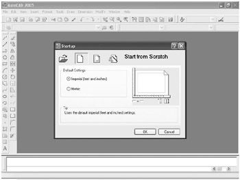
Figure 1.1: The Startup dialog box
The Startup dialog box has four buttons in the upper-left corner. The first two buttons let you set up a new drawing and choose an existing drawing to revise or update. The second two buttons use templates and wizards to initiate advanced setup routines. The contents of the middle portion of the dialog box depend on which of the four buttons you choose. By beginning a new drawing, you can get past this dialog box to the AutoCAD Graphics window.
- Click the Start From Scratch button, the second button from the left.
- In the Default Settings section, click the Imperial (Feet And Inches) radio button.
- Click OK to close the Startup dialog box. Your monitor displays the AutoCAD or LT Graphics window, sometimes called the Graphical User Interface, or GUI (see Figure 1.2).
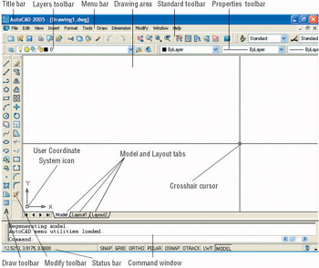
Figure 1.2: The AutoCAD Graphics windowRadio buttons are round and come in a list or a group.You can activate only one radio button at a time.
Note If the New Features Workshop window appears when you start up AutoCAD, click the second or third radio button in the window, and then click OK to remove it. You can always access it on the Help menu.
The toolbars on your screen may not be in exactly the same places as they are shown in Figure 1.2. I recommend that you set your screen to look like the one here, as it will make following through the book that much easier. Later in this chapter, you will see how to move the toolbars, display new ones and place them, and delete them.
Another feature called palettes might be visible on the far-right side of your screen when you start AutoCAD. Palettes can display as a rectangular area or as a vertical title bar. If they appear, choose Tools Tool Palettes Window to temporarily close the palettes. We’ll take a look at them in Chapters 7 and 9.
Controlling the Way AutoCAD Starts Up
You can set AutoCAD and LT to display or hide the Startup dialog box when you start AutoCAD.
- From the menu bar, choose Tools Options to open the Options dialog box.
- Click the System tab to bring it forward.
- In the General Options section, open the Startup drop-down list.
- If you want AutoCAD to display the Startup dialog box, click Show Startup Dialog Box.
- If you want AutoCAD to start up with a blank drawing, click Do Not Show A Startup Dialog.
- Click Apply, and then click OK.
The next time you start up AutoCAD, your preference will be used.
Introduction to the AutoCAD Graphics Window
At the top of the Graphics window sit the title bar, the menu bar, and three toolbars.
The title bar is analogous to the title bar in any Windows program. It contains the program name (AutoCAD or AutoCAD LT) and the title of the current drawing with its path. Below the title bar is the menu bar, where you will see the drop-down menus. Among the drop-down menus, the first two on the left and the last one on the right are Windows menus (meaning that they appear on most Windows applications). These Windows menus also contain a few commands specific to AutoCAD. The rest of the menus are AutoCAD menus.
Below these menus is the Standard toolbar, which contains 22 command buttons (LT has only 21). Several of these buttons will be familiar to Windows users; the rest are AutoCAD commands. Just below the Standard toolbar are the Layers toolbar and the Properties toolbar, which together contain three command buttons and five drop-down lists.
The blank middle section of the screen is called the drawing area. Notice the movable crosshair cursor. The crosshairs on your cursor may not extend completely across the screen. I recommend that you set them to look like they do in the figures in this book, and I will show you how to do this when we make a few changes later in this chapter.
Notice the little box at the intersection of the two crosshair lines. This is one of several forms of the AutoCAD and LT cursor. When you move the cursor off the drawing area, it changes to the standard Windows pointing arrow. As you begin using commands, it will take on other forms, depending on which step of a command you are in.
The icon with a double arrow in the lower-left corner of the drawing area is the User Coordinate System icon. It indicates the positive direction for the X and Y coordinates. You won’t need it for most of the chapters in this book, so you’ll learn how to make it invisible in Chapter 3.
The title bar and menu bar at the top of the LT screen are identical to those of AutoCAD except that AutoCAD LT appears in the title bar rather than AutoCAD.
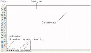
At the bottom of the drawing area are three tabs: a Model tab and two Layout tabs. You use these tabs to switch between viewing modes. (I’ll discuss viewing modes in Chapter 13.) Our example shows no toolbars floating in the drawing area, but there are two docked toolbars at the left of the drawing area. Your screen may or may not have the toolbars, or they may be in a different position. If the toolbars are within the drawing area, they will have a colored title bar. For specifics, see the section “The Toolbars” later in this chapter.
Below the drawing area is the Command window.

The Command window is where you tell the program what to do and where the program tells you what’s going on. It’s an important area, and you will need to learn how it works in detail. Three lines of text should be visible. If your screen displays fewer than three lines, you will need to make another line or two visible. You’ll learn how to do this later in this chapter in the section “The Command Window.”
The Command window in LT is identical to the one in AutoCAD.
Below the Command window is the status bar.

On the left end of the status bar, you’ll see a coordinate readout window. In the middle are eight readout buttons (LT has only seven) that indicate various drawing modes. It is important to learn about the coordinate system and most of these drawing aids (Snap, Grid, Ortho, and Osnap) early as you learn to draw in AutoCAD or LT. They will help you create neat and accurate drawings. Polar and Otrack are advanced drawing tools and will be introduced in Chapter 5. Lwt stands for Lineweight and will be discussed in Chapter 14 in the discussion on plotting. The Model button is an advanced aid that will be covered in Chapter 13. At the far right of the status bar are small icons that indicate the presence of various features for a drawing session. These features are beyond the scope of this book.
LT does not display the Otrack button on the status bar.
This has been a quick introduction to the various parts of the Graphics window. I didn’t mention a couple of items that might be visible on your screen. You might have scroll bars below and to the right of the drawing area, and you might have a menu on the right side of the drawing area. Both features can be useful, but they can also be a hindrance and can take up precious space in the drawing area. They won’t be of any use while working your way through this book, so I suggest that you remove them for now.
To temporarily remove these features, follow these steps:
- Choose Tools Options to open the Options dialog box (shown in Figure 1.3). It has nine tabs (LT has only eight) across the top that act like tabs on file folders.
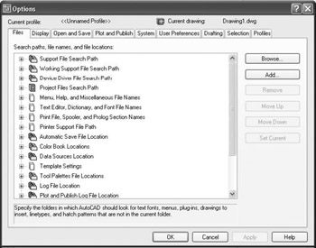
Figure 1.3: The Options dialog box - Click the Display tab, which is shown in Figure 1.4. Focus on the rectangular area titled Window Elements. If scroll bars are visible on the lower and right edges of the drawing area, the Display Scroll Bars In Drawing Window check box will be checked.
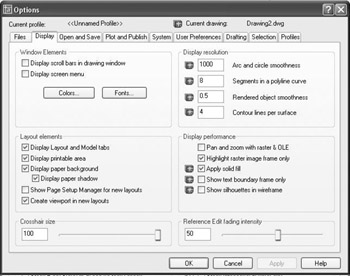
Figure 1.4: The Options dialog box open at the Display tab - Click the check box to turn off the scroll bars. Also click the Display Screen Menu check box to turn off the screen menu. Don’t click the OK button yet.
Another display setting that you might want to change at this point controls the color of the cursor and the drawing area background. The illustrations in this book show a white background and black crosshair cursor, but you might prefer to reverse the colors. To do so, follow these steps:
- In the Window Elements area of the Display tab, click the Colors button to open the Color Options dialog box (see Figure 1.5). In the middle of the dialog box, in the Window Element drop-down list box, Model Tab Background should be visible. If it’s not, open the drop-down list and select it.
LT doesn’t have the Screen menu, so the option to turn it off is not on LT’s Display tab.
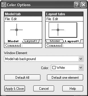
Figure 1.5: The Color Options dialog box - Move to the Color drop-down list, which is below the Window Element drop-down list. If your drawing area background is currently white, a square followed by the word White is displayed. Open the Color drop-down list. Scroll to Black (or the background color you want) and select it. The drawing area will now be that color, and the cursor color will change to white, as shown in the Model Tab preview window in the upper-left corner of the dialog box.
- Click the Apply & Close button to close the Color Options dialog box.
- Don’t close the Options dialog box yet.
- If you want the lines of your crosshair cursor to extend completely across the screen, go to the lower-left corner of the Display tab
(lower-right for LT) and move the slider to change the Crosshair Size setting to 100. - Click OK to close the Options dialog box.
Your screen and crosshair cursor will take on their newly assigned colors, and the crosshair lines should extend across the drawing area.
| Tip |
If you choose a color other than black as the drawing area background color, the color of the crosshair cursor remains the same as it was (black). To change the crosshair color, in the Color Options dialog box, open the Window Element drop-down list, and select Model Tab Pointer. Then select a color from the Color drop-down list. |
The Command Window
Just below the drawing area is the Command window. This window is actually separate from the drawing area and behaves like a Windows window—that is, you can drag it to a different place on the screen and resize it, although I don’t recommend that you do this at first. If you currently have fewer than three lines of text in the window, you will need to increase the window’s vertical size. To do so, move the cursor to the horizontal boundary between the drawing area and the Command window until it changes to an up-and-down arrow broken by two parallel horizontal lines.

Hold down the left mouse button and drag the cursor up by approximately the amount that one or two lines of text would take up, and then release the mouse. You should see more lines of text, but you might have to try this a couple of times to display exactly three lines. When you close the program, the new settings will be saved, and the next time you start up AutoCAD, the Command window will display three lines.
The Command window is where you give information to AutoCAD and where AutoCAD prompts you for the next step in executing a command. It is a good practice to get into the habit of keeping an eye on the Command window as you work on your drawing. Most errors occur when you are not taking a look at it frequently.
Before you begin to draw, take a close look at the menus, toolbars, and keyboard controls.
| Note |
In many cases, you can start AutoCAD commands in a number of ways: from drop-down menus, from the toolbars, and from the keyboard. When you get used to drawing with AutoCAD, you will learn some shortcuts that start commands quickly, and you will find the way that is most comfortable for you. |
Drop Down Menus
The menu bar, just below the title bar (see Figure 1.2 earlier in this chapter), consists of 11 words and an icon. Click any of these to display a drop-down menu. The icon on the left end and the File and Edit menus are included with all Windows-compatible applications, although they are somewhat customized to work with AutoCAD. The menu associated with the icon contains commands to control the appearance and position of the drawing area.
Commands in the File menu are for opening and saving new and existing drawing files, printing, linking on the Internet, exporting files to another application, choosing basic utility options, and exiting the application. The Edit menu contains the Undo and Redo commands, the Cut and Paste tools, and options for creating links between AutoCAD files and other files. The Help menu (the last menu on the right) works like all Windows Help menus and contains a couple of AutoCAD-specific entries as well, including some online resources and a context-sensitive help feature called the Info Palette.
The other eight menus contain the most-often-used AutoCAD commands. You will find that if you can master the logic of how the commands are organized by menu, you can quickly find the command you want. Here is a short description of each of the other AutoCAD drop-down menus:
ViewContains tools for controlling the display of your drawing file.
InsertContains commands for placing drawings and images or parts of them inside other drawings.
FormatContains commands for setting up the general parameters for a new drawing.
ToolsContains special tools for use while you are working on the current drawing, such as those for finding the length of a line or for running a special macro.
DrawContains commands for creating new objects (such as lines or circles) on the screen.
DimensionContains commands for dimensioning a drawing.
ModifyContains commands for changing existing objects in the drawing.
WindowContains commands for displaying currently open windows and lists currently open drawing files.
The Toolbars
Just below the drop-down menus is the most extensive of the toolbars—the Standard toolbar.

The 22 icons on the AutoCAD Standard toolbar don’t appear as buttons until you point to them, and they are arranged into seven logical groups. The icons on the left half of the Standard toolbar are mostly for commands used in all Windows-compatible applications, so you might be familiar with them. The icons on the right half of the Standard toolbar are AutoCAD commands that you use during your regular drawing activities for a variety of tasks. You use these commands to take care of a number of tasks, including the following:
- Changing the view of the drawing on the screen
- Changing the properties of an object, such as color or linetype
- Borrowing parts of an unopened drawing to use in your current drawing
- Displaying a set of palettes that contain objects you can use in your drawing
LT has only 21 Standard toolbar buttons. It’s missing the Sheet Set Manager button because it doesn’t have this feature.
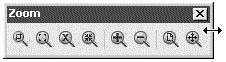
Toolbar Flyouts
Notice that one icon on the Standard toolbar has a little triangular arrow in the lower-right corner. This arrow indicates that clicking this icon displays more than one command. Follow these steps to see how this special icon works.
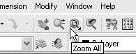
- Move the cursor up to the Standard toolbar, and point to the icon that has a magnifying glass with a rectangle in it.
- Rest the arrow on the button for a moment without clicking. A small window opens just below it, displaying the command the button represents. In this case, the window should say “Zoom Window.” This is a tool tip—all buttons have them. Notice the small arrow in the lower-right corner of the icon. This is the multiple-command arrow mentioned earlier.
- Place the arrow cursor on the button and hold down the left mouse button. A column of eight buttons drops down vertically below the original button. The top button in the column is a duplicate of the button you clicked. This column of buttons is called a toolbar flyout.
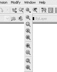
- While still holding down the mouse button, drag the arrow down over each button until you get to the one that has a magnifying glass with a piece of white paper on it. Hold the arrow there until you see the tool tip. It should say “Zoom All.” Now release the mouse button. The flyout disappears, and AutoCAD executes the Zoom All command. Look in the Command window at the bottom of the screen.

At the end of the top line of text is “_all.” This tells you that you have used the All option of the Zoom command. This flyout is called the Zoom flyout because it contains tools for changing views of the drawing, or “zooming around in the drawing.”
The Zoom All command changes the view of your drawing to include special preset parameters. We’ll look at this command in Chapter 3.
- Look at the Standard toolbar where the Zoom Window button was previously. Notice that it’s been replaced by the Zoom All button.
Tip On a toolbar flyout, the button you select replaces the button that was on the toolbar. This arrangement is handy if you are going to be using the same command several times, because the button for the command is readily available and you don’t have to open the flyout to select it again. The order of the flyout buttons remains the same, so when you open the Zoom flyout again, the Zoom Window button will be at the top of the list. You will need to become familiar with any flyout buttons you use, because the last one used becomes the representative button on the home toolbar.
The behavior of the Zoom flyout on the Standard toolbar is the same as the behavior of flyouts in general.
| Note |
Whenever you start up AutoCAD or LT for a new drawing session, the toolbars are reset and contain the original flyout buttons. |
The toolbar flyouts are actually regular toolbars that have been attached to another toolbar. There are 29 toolbars in all, and only 2 are flyouts—the Zoom flyout I just discussed, and the Insert flyout on the Draw toolbar. You can display the Zoom and Insert flyouts as regular toolbars, independent of the Standard and Draw toolbars.
LT has 22 toolbars compared with AutoCAD’s 29. The additional toolbars in AutoCAD are almost all for 3D and rendering tools.
Displaying and Arranging Toolbars
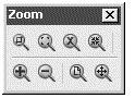
In this section, I’ll use the Zoom toolbar to show you some ways you can control and manipulate toolbars. Follow these steps:
- Right-click any toolbar button on the screen to open the Toolbars menu (see Figure 1.6).
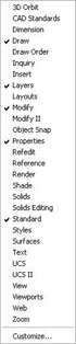
Figure 1.6: The Toolbars menu - Click Zoom to display the Zoom toolbar in the form of a floating box in the drawing area.
Notice that the Zoom toolbar now has a title bar. Toolbars that are positioned on the drawing area have title bars. By placing the cursor on the title bar and holding down the left mouse button, you can drag the toolbar around the screen. Try this with the Zoom toolbar.
- Click and drag the Zoom toolbar to the right side of the screen. You will notice that as you drag it, the toolbar stays put, and you are dragging a rectangle of the same size as the toolbar (see Figure 1.7). As you drag the rectangle to the right of the drawing area and begin to move it off the drawing area onto the right side of the screen, the rectangle becomes taller and thinner.
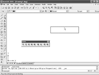
Figure 1.7: Dragging the Zoom toolbar - Release the left mouse button once the toolbar is out of the drawing area. The rectangle changes to the Zoom toolbar, which is now positioned off the drawing area without its title bar.

This procedure is called docking a toolbar. Notice how the Standard and Object Properties toolbars have no title bars—they are docked.
- Move the cursor arrow to the left end of the Standard toolbar so the point of the arrow is on the two vertical grab bars.
- Hold down the left mouse button while the cursor arrow is on the Standard toolbar grab bars, and drag the toolbar onto the drawing area. Release the mouse button. The Standard toolbar now has a title bar, and the space it was occupying at the top of the screen has been filled, making the drawing area a little larger, as you can see in Figure 1.8. The Standard toolbar is now a floating toolbar and can be moved around the drawing area.
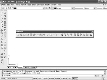
Figure 1.8: The Standard toolbar on the drawing area
Floating toolbars don’t affect the size of the drawing area, but they cover your drawing. Each row or column of docked toolbars takes up space that would otherwise be drawing area. You have to decide how many docked and floating toolbars you need on the screen at a time. A good way to start is to leave the Standard, Layers, and Properties toolbars docked at the top of the screen and the Draw and Modify toolbars docked on the left side of the screen, as shown earlier in Figure 1.2.
Grab bars are the two lines at the left end of a horizontal toolbar or at the top of a vertical one. They represent the one place to grab a docked toolbar to move it. You can also change a docked toolbar into a floating toolbar by double-clicking its grab bars.
To put the Standard toolbar back where it was and delete the Zoom toolbar, follow these steps:
- Drag the Standard toolbar up to its former position above the Layers and Properties toolbars.
- Drag the Zoom toolbar back onto the drawing area, using the grab bars. You can easily change the shape of any floating toolbar by dragging its edge. Let’s change the shape of this toolbar.
- Move the cursor to the far-right edge of the Zoom toolbar until the crosshair cursor changes to a two-way arrow.
Hold down the left mouse button with the cursor on the right edge of the toolbar, and drag the arrow to the left until the rectangle changes shape. Release the mouse button.
You can reshape and reposition each floating toolbar to fit on the drawing area just as you like it. You won’t need the Zoom toolbar just now, so remove it.
- Move the cursor up to the title bar and click the box with a in it to close the Zoom toolbar.
If your Draw and Modify toolbars are positioned on the left side of the drawing area as shown earlier in Figure 1.2, continue with the next section. If these toolbars are in another location on the drawing area, try the steps you used in this section to dock them on the left side. If the toolbars are not visible, right-click any visible toolbar button, and then choose Draw. Drag the Draw toolbar to the left side of the drawing area and dock it. Do the same with the Modify toolbar, positioning it next to the Draw toolbar.
This arrangement of the toolbars will be convenient because you often use commands on these five toolbars. When you need other toolbars temporarily, you can use the Toolbars menu to display them in the drawing area and let them float.
Custom Toolbars
You can customize each toolbar, and you can build your own custom toolbars with only the command buttons you use. You can even design your own buttons for commands that aren’t already represented by buttons on the toolbars. These activities are for more advanced users, however, and are not covered in this book. To find out more about how to customize toolbars, see Mastering AutoCAD 2005 and AutoCAD LT 2005 by George Omura (Sybex, 2004).
Profiles
|
|
As you become accustomed to working with AutoCAD, you will develop your own preferences for the layout of the AutoCAD Graphics window, including: |

- Which toolbars are docked and where
- The shape of the crosshair cursor
- The background color of the drawing area
LT does not have the Profiles feature. LT users can skip ahead to “The Keyboard” section.
You control these features from the Options dialog box. If you share your workstation with others, you will find it convenient to set up a profile and save it. That way, if someone changes the organization of your Graphics window, you can quickly restore your preferences. Here’s how to do this:
- Set the toolbars on your screen as you prefer them.
- Choose Tools Options to open the Options dialog box, click the Display tab, and make any changes you want to the color of the background and cursor or to the visibility of slide bars.
- Click the Profiles tab, which is shown in Figure 1.9.
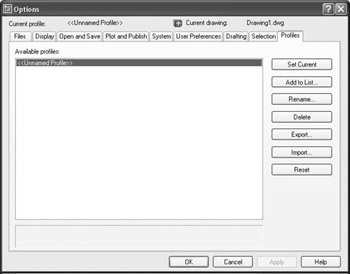
Figure 1.9: The Profiles tab in the Options dialog box - Click the Add To List button to open the Add Profile dialog box, which is shown in Figure 1.10.
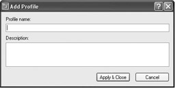
Figure 1.10: The Add Profile dialog box - In the Profile Name box, type the name of your profile. You also have the option of entering a description below the name.
- Click Apply & Close. Your new profile appears in the Available Profiles list. This new profile is the arrangement of the screen that was current when you added your profile to the list.
- Click OK to close the Options dialog box.
The next time you start up AutoCAD, if the Graphics window is not set up the way you want, follow these steps:
- Choose Tools Options to open the Options dialog box, and click the Profiles tab.
- Highlight your profile, and click the Set Current button.
- Click OK. The Graphics window will then be set to your preferences.
The Keyboard
The keyboard is an important tool for entering data and commands. If you are a good typist, you can gain speed in working with AutoCAD by learning how to enter commands from the keyboard. AutoCAD provides what are called alias keys—single keys or key combinations that will start any of several often-used commands. You can add more or change the existing aliases as you get more familiar with the program.
In addition to the alias keys, you can use several of the F keys (function keys) on the top row of the keyboard as two-way or three-way toggles (switches) to turn AutoCAD functions on and off. Although buttons on the screen duplicate these functions (Snap, Grid, and so on), it is sometimes faster to use the F keys.
Finally, you can activate commands on the drop-down menus from the keyboard, rather than using the mouse. If you press the Alt key, an underlined letter, called a hotkey, appears on each menu. Pressing the key for the underlined letter activates the menu. Each command on the menu also has a hotkey. Once you activate the menu with the hotkey combination, you can type the underlined letter of these commands. For a few commands, this method can be the fastest way to start them up and to select options.
While working in AutoCAD, you will need to key in a lot of data, such as dimensions and construction notes, answer questions with “yes” or “no,” and use the arrow keys. You will use the keyboard constantly. It may help to get into the habit of keeping the left hand on the keyboard and the right hand on the mouse—if you are right-handed—or the other way around, if you are left-handed.
The Mouse
Your mouse will most likely have two or three buttons. (If it’s an IntelliMouse, it will have two or more buttons with a wheel between them.) So far in this chapter, you have used the left mouse button for choosing menus, commands, or command options or for holding down the button and dragging a menu, toolbar, or window. The left mouse button is the one you will be using most often, but you will also use the right mouse button.
While drawing, you will use the right mouse button for the following three operations:
- To display a menu containing options relevant to the particular step you are in at the moment
- To use in combination with the Shift or Control key to display a menu containing special drawing aids called Object Snaps (see Chapter 10)
- To display a menu of toolbars when the pointer is on any icon of a toolbar that is currently open
If you have a three-button mouse, the middle button is usually programmed to display the Object Snap menu, instead of using the right button with the Shift key. If you have an IntelliMouse, you can use the wheel in several ways to control the view of your drawing. I’ll cover those methods in subsequent chapters.
AutoCAD makes extensive use of toolbars and the right-click menu feature. This makes your mouse an important input tool. The keyboard is necessary for inputting numeric data and text, and it has hotkeys and aliases that can speed up your work. But the mouse is the primary tool for starting commands, selecting options, and controlling toolbars.
The next chapter will familiarize you with a few basic commands that will enable you to draw a small diagram. If you are going to take a break and want to close AutoCAD, choose File Exit, and choose not to save the drawing.
Are You Experienced?
Now you can
- open a new drawing using the Start Up dialog box
- recognize the elements of the AutoCAD Graphics window
- understand how the Command window works and why it’s important
- use drop-down menus
- call up and control the positioning of toolbars
- save a profile of your screen setup in AutoCAD
Introduction
- Getting to Know AutoCAD
- Basic Commands to Get Started
- Setting Up a Drawing
- Gaining Drawing Strategies: Part 1
- Gaining Drawing Strategies: Part 2
- Using Layers to Organize Your Drawing
- Grouping Objects into Blocks
- Generating Elevations
- Working with Hatches and Fills
- Controlling Text in a Drawing
- Dimensioning a Drawing
- Managing External References
- Using Layouts to Set Up a Print
- Printing an AutoCAD Drawing
- Appendix A Look at Drawing in 3D
EAN: N/A
Pages: 159
