Dimensioning a Drawing
Dimensioning aDrawing
Overview
- Setting up a dimension style
- Dimensioning the floor plan of the cabin
- Modifying existing dimensions
- Modifying existing dimension styles
Dimensions are the final ingredient to be added to your drawing. To introduce you to dimensioning, I’m going to follow a pattern similar to the one I used in the previous chapter on text.
Dimension Styles
Dimension styles are similar to text styles, but are more complex. You set them up in the same way, but many parameters control the various parts of dimensions, including the dimension text.
Before you start setting up a dimension style, you need to make a few changes to your drawing to prepare it for dimensioning.
- Open Cabin10c and zoom in to the upper half of the drawing.
- Create a new layer called Dim1. Assign it a color and make it current.
- Freeze the Grid layer.
- Set Endpoint Osnap to be running.
- Set the status bar so that only the Osnap and Model buttons are in the on position.
- Right-click any button on any toolbar on the screen to display the toolbar menu. Click Dimension to open the Dimension toolbar on the drawing area in the form of a floating toolbar.
- Move the Dimension toolbar to the top center of the drawing area, being careful to avoid docking it. (You learned about moving toolbars around on the screen in Chapter 1.) Your drawing will look like Figure 11.1.
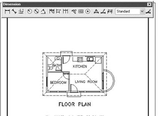
Figure 11.1: The floor plan of Cabin10c with the Dimension toolbar centered at the top of the drawing area
Making a New Dimension Style
Each dimension has several components: the dimension line, arrows or tick marks, extension lines, and the dimension text (see Figure 11.2). An extensive set of variables that is stored with each drawing file controls the appearance and location of these components. You will work with these variables through a series of dialog boxes that have been designed to make setting up a dimension style as easy and trouble free as possible. Remember that AutoCAD is designed to be used by drafters from many trades and professions, each of which has its own standards for drafting. To satisfy these folks’ widely varied needs, AutoCAD dimensioning features have many options and settings for controlling the appearance and placement of dimensions in drawings.
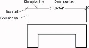
Figure 11.2: The parts of a dimension
Naming a Dimension Style
Every dimension variable has a default setting, and these as a group constitute the default Standard dimension style. As in defining text styles, the procedure is to copy the Standard dimension style and rename the copy—in effect, making a new style that is a copy of the default style. You then make changes to this new style so it has the settings you need to dimension your drawing.
- Click the Dimension Style button on the right end of the Dimension toolbar to open the Dimension Style Manager dialog box (see Figure 11.3). On the top left in the Styles list box, Standard is listed.
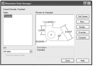
Figure 11.3: The Dimension Style Manager dialog box - Click the New button on the right side of the Dimension Style Manager dialog box to open the Create New Dimension Style dialog box.
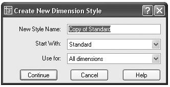
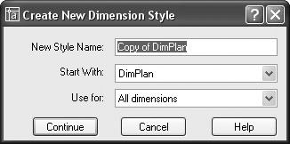
- In the New Style Name text box, Copy Of Standard is highlighted. Type DimPlan but don’t press yet. Notice that Standard is in the Start With drop-down list just below. Because it is the current and only dimension style in this drawing, the new dimension style you are about to define will begin as a copy of the Standard style. This is similar to the way in which new text styles are defined (as you saw in Chapter 10). The Use For drop-down list allows you to choose the kinds of dimensions to which the new style will be applied. In this case, it’s all dimensions, so we don’t need to change this.
- Click the Continue button. The Create New Dimension Style dialog box is replaced by the New Dimension Style: DimPlan dialog box (see Figure 11.4). It has six tabs. You have created a new dimension style that is a copy of the Standard style, and now you will make the changes necessary to set up DimPlan to work as the main dimension style for the floor plan of the cabin.
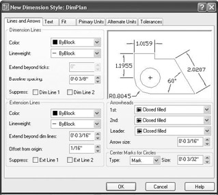
Figure 11.4: The New Dimension Style dialog box with DimPlan as the current style and Lines And Arrows as the active tab - Be sure the Lines And Arrows tab is active (on top). If it’s not, click it.
Using the Lines And Arrows Tab
You will use the Lines And Arrows tab to control the appearance of the dimension and extension lines, the arrowheads, and the center marks.
- In the Arrowheads area, click the down arrow in the first drop-down list to open the list of arrowheads.
- Click Architectural Tick. The drop-down list closes with Architectural Tick displayed in the first and second drop-down lists. In the preview window above the Arrowheads area, a graphic displays the new arrowhead type. It doesn’t display the actual thickness that the tick mark line will have in your drawing.
Tick marks are used almost exclusively by the architecture profession. This list contains options for several kinds of arrowheads, dots, and so on.
- In the Arrow Size spin box, highlight the default setting and change it to 1⁄8.
- Move to the Dimension Lines area. Change the Extend Beyond Ticks setting from 0" to 3⁄32" by highlighting the 0 and typing 3⁄32. This will extend the dimension line past the tick mark a short distance.
- In the Extension Lines area, highlight the Extend Beyond Dim Lines setting and change it to 1⁄8. This controls how far the extension line will extend beyond the dimension line.
Before saving these changes, make some more modifications to the DimPlan style.
Making Changes in the Text Tab
The settings in the Text tab control the appearance of dimension text and how it is located relative to the dimension and extension lines.
- Click the Text tab in the New Dimension Style dialog box. Settings in three areas affect the appearance and location of dimension text. Look ahead to Figure 11.5 for a graphic of the Text tab. The preview window appears in all tabs and is updated automatically as settings are modified. Move to the Text Appearance area in the upper-left corner of the dialog box where there are six settings that control how the text looks. We are concerned about only two of them.
- Click the Browse button that sits at the right end of the Text Style drop-down list to open the Text Style dialog box. Set up a new text style called Dim that has the following parameters:
- Romand.shx font
- 0'-0" height
- 0.8000 width factor
- All other settings at their default
If you need a reminder on creating text styles, refer to Chapter 10. Apply this text style to make it current, and then close the Text Style dialog box.
- Back in the Text tab, open the Text Style drop-down list and select the new Dim style from the list.
- Change the Text Height setting to 3⁄32".
- Move down to the Text Placement area. These settings determine where the text is located, vertically and horizontally, relative to the dimension line. There are two settings to change here.
- Open the Vertical drop-down list and select Above. At this setting, the text will sit above the dimension line and not break the line into two segments. Set the Offset From Dim Line setting to 1⁄32".
Many trades and professions use the Centered option for vertical text placement and the Horizontal option for text alignment.
- Now move to the Text Alignment area. Two radio buttons control whether dimension text is aligned horizontally or with the direction of the dimension line. The ISO Standard option aligns text depending on whether the text can fit between the extension lines. Only one of the buttons can be active at a time. Horizontal should already be active. Click the Aligned With Dimension Line button. Notice how the appearance and location of the text has changed in the preview window. This finishes our work in this tab. The settings should look like Figure 11.5.
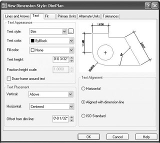
Figure 11.5: The Text tab with settings for the DimPlan style
There are four more tabs with settings, but we’ll be making changes in only two of them: Fit and Primary Units.
Working with Settings in the Fit Tab
The settings in the Fit tab control the overall scale factor of the dimension style and how the text and arrowheads are placed when the extension lines are too close together for both text and arrows to fit.
- Click the Fit tab in the New Dimension Style dialog box. Look ahead to Figure 11.6 to see a graphic of the Fit tab.
- In the upper-left corner, in the Fit Options area, click the Text radio button.
For your own work, you may have to experiment with the settings on this tab.
- In the Text Placement area, click the Over The Dimension Line, Without A Leader radio button.
- Make no changes in the Fine Tuning area for now. Move to the Scale For Dimension Features area. Be sure the Use Overall Scale Of radio button is active. Set the scale to 96. (Use the highlight-and-type method described in step 4 of the earlier section, “Using the Lines And Arrows Tab.”) The settings in the Fit tab should look like Figure 11.6.
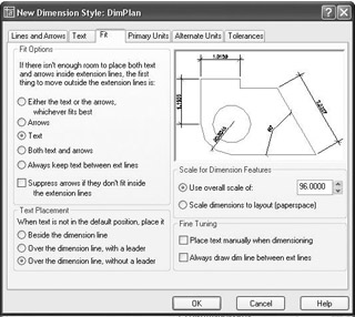
Figure 11.6: The new settings in the Fit tab
Setting Up the Primary Units Tab
In the preview window, you may have noticed that the numbers in the dimension text maintained a decimal format with four decimal places, rather than the feet and inches format of the current Architectural units. Dimensions have their own units setting, independent of the basic units for the drawing as a whole. In the Primary Units tab, you will set the dimension units.
- Click the Primary Units tab and take a peek ahead at Figure 11.7 to see how it’s organized. There are two areas: Linear and Angular Dimensions. Within each of these areas are a few settings and one or two nested areas.
- In the Linear Dimensions area, starting at the top, make the following changes:
- Change the Unit Format setting from Decimal to Architectural.
- Change the Fraction Format setting to Diagonal.
- In the Zero Suppression area, uncheck 0 Inches.
Note Zero Suppression controls (a) whether the zero is shown for feet when the dimensioned distance is less than one foot and (b) whether the zero is shown for inches when the distance is a whole number of feet. For the cabin drawing, we will suppress the zero for feet, but we will show the zero for inches. So 9" will be shown as 9", and 3' will be shown as 3'-0".
- In the Angular Dimensions area, leave Decimal Degrees as the Units Format, and change Precision to two decimal places, as you did for the basic drawing units in Chapter 3. For now, leave the Zero Suppression area as it is. After these changes, the Primary Units tab will look like Figure 11.7.
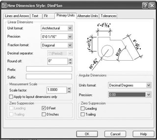
Figure 11.7: The Primary Units tab after changes have been made
Of the last two tabs, Alternate Units can be used by any industry involved in global projects, and Tolerances are used mostly by the mechanical engineering trades and professions. We won’t need to make any changes to these tabs for this tutorial, but we’ll take a brief look at those tabs before we start dimensioning the cabin.
It’s time to save these setting changes to the new DimPlan dimension style and begin dimensioning the cabin.
- Click the OK button at the bottom of the New Dimension Style dialog box. You will be returned to the Dimension Style Manager dialog box (see Figure 11.8).
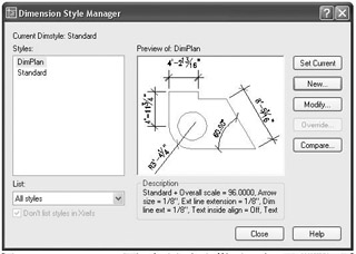
Figure 11.8: The Dimension Style Manager dialog box with DimPlan listedDimPlan is displayed with a gray swatch in the Styles list box, along with Standard. In the lower-right corner of the dialog box, in the Description area, the following information is presented about the new style: the name of the original style that the new style is based on and the changes that were made to the original style to create the new style. Unfortunately, the area is much too small to display all the changes we’ve made, so use the chart later in this section as a reference.
- Click DimPlan to highlight it in a dark blue; then click the Set Current button. Finally, click the Close button. You are returned to your drawing, and the Dimension toolbar now displays DimPlan in the Dim Style Control drop-down list. This indicates that DimPlan is now the current dimension style.
You have made changes to 17 settings that control dimensions. This is not too many, considering that there are more than 50 dimension settings. Here is a summary of the changes you’ve made to make the dimensions work with the cabin drawing:
|
Tab |
Setting |
Default Setting |
DimPlan |
|---|---|---|---|
|
Lines And Arrows |
Arrowheads |
Closed Filled |
Architectural Tick |
|
Arrowhead Size |
3/16" |
1/8" |
|
|
Dim Line Extension |
0" |
3/32" |
|
|
Ext. Line Extension |
3/16" |
1/8" |
|
|
Text |
Text Style |
Standard |
DimPlan |
|
Text Height |
3/16" |
3/32" |
|
|
Text Vertical Justification |
Centered |
Above |
|
|
Offset From Dim Line |
3/32" |
3/32" |
|
|
Text Alignment |
Horizontal |
Aligned With Dimension Line |
|
|
Fit |
Fit Options |
Either—whichever is best |
Text |
|
Text Placement |
Beside The Dimension Line |
Over the Dimension Line, Without A Leader |
|
|
Overall Scale |
1.0000 |
96.0000 |
|
|
Primary Units |
Unit Format |
Decimal |
Architectural |
|
Fraction Format |
Horizontal |
Diagonal |
|
|
Zero Suppression |
Feet, Inches |
Feet only |
|
|
Angular Precision |
No decimal places |
Two decimal places |
You will change a few more settings throughout the rest of this chapter as you begin to dimension the cabin in the next set of exercises. Let’s look briefly at the Alternate Units and Tolerances tabs.
The Alternate Units Tab
If your work requires your dimensions to display both Metric and Architectural units, use the Alternate Units tab in the New Dimension Style dialog box. In the example shown here, the primary units are Architectural and were set in the previous section. Now we’ll set up the alternate units.
- Click the Dimension Style button on the Dimension toolbar.
- Highlight DimPlan if it’s not already highlighted.
- Click the Modify button.
- Click the Alternate Units tab. When we’re finished here, it will look like Figure 11.9. There are only three or four changes to be made on this tab.
- In the upper-left corner of the tab, click to put a check mark in the Display Alternate Units check box. This will make the rest of the settings on the tab available to us for making changes.
- If Decimal is not displayed in the Unit Format drop-down list, open it and select Decimal.
- If the precision is not set to 0, open that drop-down list and select that level of precision.
- Set Multiplier For Alt Units to 25.4. This will make millimeters the alternate units.
If you want centimeters to be the alternate units, change the Multiplier For Alt Units setting to 2.54 and set the precision to 0.00.
- Finally, in the lower-right quarter of the tab, in the Placement area, select Below Primary Value. This will have the effect of placing the alternate units below the primary units. The tab should look like Figure 11.9a, and the resulting dimensions for the upper portion of the floor plan should look like Figure 11.9b.
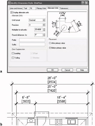
Figure 11.9: The Alternate Units tab after being set up for millimeters (a) and the resulting horizontal dimensions (b) - Don’t save this setting. We won’t be using alternate units when we dimension the cabin.
The Tolerances Tab
AutoCAD offers features whose options help you create several kinds of tolerances. In the Tolerances tab, you have four methods for doing what is called lateral tolerances, the traditional kind of tolerance that most draftspeople are familiar with. This is the plus or minus kind of tolerance. Take a look at the choices in the Method drop-down list shown in Figure 11.10. Each of these is a method for displaying a plus/minus type of tolerance:
SymmetricalThis method is for a single plus-or-minus expression after the base dimension; used when the upper allowable limit of deviation is identical to that for the lower limit, as in 1.0625 0.0025.
DeviationThis method is for the instance in which the upper allowable deviation is different from that of the lower deviation. For example, the upper limit of the deviation can be +0.0025, and the lower limit can be –0.0005. As in the Symmetrical method, these follow the base dimension.
LimitsIn this method, the tolerances are added or subtracted to the base dimension, resulting in maximum and minimum total values. The maximum is placed over the minimum. In the example for the Symmetrical method, 1.0650 would be the maximum and on top of 1.0600, the minimum.
BasicThe base dimension is left by itself, and a box is drawn around it, indicating that the tolerances are general, apply to several or all dimensions in boxes, and are noted somewhere else in the drawing. Often, basic dimensions are shown when a dimension is theoretical or not exact.
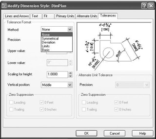
Figure 11.10: The top of the Tolerances tab, showing the Method drop-down list options
When you select one of these options, the settings in the tab become available. If you select Deviation, all settings become available.
PrecisionControls the overall precision of the tolerances.
Upper Value and Lower ValueThe actual values of the tolerances.
Scaling For HeightThe height of the tolerance text. A value of 1 here sets the tolerance text to match that of the base dimension. A value of greater than 1 makes the tolerance text greater than the base dimension text, and a value of less than 1 makes it smaller than the base dimension text.
Vertical PositionWhere the base dimension is placed vertically relative to the tolerances. It can be in line with the upper or lower tolerance or in the middle.
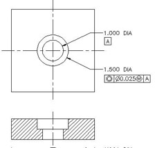
The Zero Suppression areas at the bottom, when checked, suppress extra zeros that occur before or after the decimal point. If you set up the Tolerances tab as shown in Figure 11.11a, a dimension looks like the one shown in Figure 11.11b.
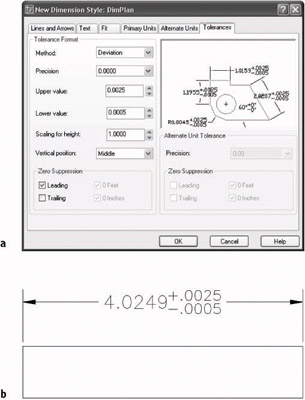
Figure 11.11: The Tolerances tab with some settings changed (a), and a dimension with deviation tolerances (b)
A more complex family of tolerances is available through the Dimension toolbar. It’s called geometric tolerancing and involves setting up a series of boxes that contain symbols and numbers that describe tolerance parameters for forms, positions, and other geometric features. Usually there are two to six boxes in a row with the possibility of multiple rows. These all constitute the feature control frame, which eventually is inserted in the drawing and attached in some way to the relevant dimension.
- Click the Tolerance button on the Dimension toolbar to open the Geometric Tolerance dialog box, in which you set up the feature control frame. The black squares will contain symbols, and the white rectangles are for tolerance or datum values or for reference numbers.
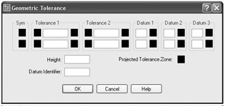
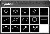
- Click in the top SYM box on the left to open the Symbol window, which contains 14 standard symbols that describe the characteristic form or position that the tolerance is being used for. When you select one of the symbols, the window closes, and the symbol is inserted into the SYM box.
- Click the first black square of Tolerance 1. A diameter symbol is inserted.
- Now click the last black square of Tolerance 1. The Material Condition window opens and displays the three material condition options. When you click one, it is inserted.
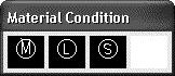
You can insert any of these three symbols in Tolerance 2 and Datum 1, 2, or 3, if you need them.
- Now you can fill in the actual tolerance value(s) and datum references in the white boxes.
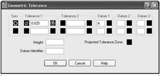
- When you are finished, click OK. The feature control frame can be inserted into your drawing like a block and can be referenced to a part or a dimension.
This exercise is intended solely to show you the tools that AutoCAD provides for setting up the most commonly used lateral and geometric tolerances when you use the Tolerances tab in the Dimension Style Dialog box and the Tolerance button on the Dimension toolbar. My intention here is not to explain the methodology of geometric tolerances or the meanings of the various symbols, numbers, and letters used in them. That is a subject beyond the scope of this book.
Placing Dimensions on the Drawing
Upon returning to your drawing, it should still look almost exactly like Figure 11.1 (shown earlier), and it should have the following:
- A new layer called Dim1, which is current
- A new dimension style called DimPlan, which is current and is now displayed in the drop-down list on the Dimension toolbar
- The Grid layer frozen
- Endpoint Osnap running
- On the status bar:Ortho, Polar, and for AutoCAD, Otrack off
- A new text style called Dim, which is current
Horizontal Dimensions
First, you will dimension across the top of the plan, from the corner of the building to the center of the interior wall, then to the other corner. You’ll then dimension the roof.
- Click the Linear button at the left end of the Dimension toolbar to activate the Dimlinear command. The prompt reads Specify first extension line origin or <select object>:.
- Pick the upper-left corner of the cabin walls. The prompt changes to Specify second extension line origin:. At this point, zoom in to the bathroom area until you can see the wall between the bathroom and kitchen, as well as the back wall, close up.
- Activate Midpoint Osnap and click the upper jamb line of the bathroom door opening when the triangle appears at the jamb’s midpoint (see Figure 11.12).
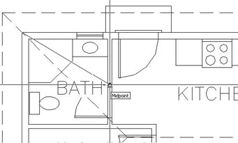
Figure 11.12: Selecting the jamb with Midpoint Osnap - Use Realtime Pan to pan the drawing down until there’s room above the roof line to place the dimension. Notice how the dimension appears in ghosted form attached to, and moving with, the cursor (see Figure 11.13a). Notice that the right extension line starts just above the midpoint of the jamb you just picked.

Figure 11.13: The dimension attached to the cursor (a), and adjusted after placement (b) - Move the cursor until the dimension line is about 3' above the back step. Click to place it.
- Click anywhere on the new dimension. Five grips appear. Click the grip at the bottom of the right extension line. Select Perpendicular Osnap and move the cursor up to the exterior wall line. When the Osnap symbol appears, click. The right extension line has been adjusted. Press Esc to remove the grips (see Figure 11.13b).
Your first dimension is completed.
When dimensioning walls, you usually dimension to the outside of the exterior ones and to the center of the interior ones. The next dimension will run from the right side of the first dimension to the right corner.
| Note |
Studs are the vertical 2" 4" or 2" 6" members in the framing of a wall. When dimensioning buildings that have stud walls, architects usually dimension to the face of the stud for the outside walls, but I am not able to go into that level of detail in this book. |
The Continue Command
AutoCAD has an automatic way of placing adjacent dimensions in line—the Continue command.
- Zoom out and pan until you have a view of the upper wall and roof line, with space above them for dimensions (see Figure 11.14).
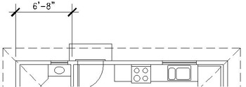
Figure 11.14: The result of zooming and panning for a view of the top of the floor plan - Click the Continue button on the Dimension toolbar. The prompt reads Specify a second extension line origin or [Undo/Select] <Select>:. All you need to do here is pick a point for the right end of the dimension—in this case, the upper-right corner of the walls.
- Click the upper-right corner of the house. The second dimension is drawn in line with the first (see Figure 11.15). Note that the same prompt has returned to the Command window. You could keep picking points to place the next adjacent dimension in line, if there was need of one. Press Esc to cancel the Continue command.
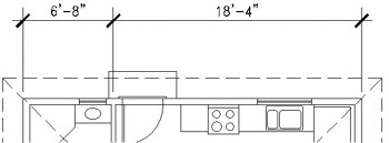
Figure 11.15: The completion of the Continue command
With the Continue command, you can dimension along a wall of a building quickly, just by picking points. AutoCAD assumes that the last extension line specified for the previous dimension will coincide with the first extension line of the next dimension. If the extension line you need to continue from is not the last one specified, press at the prompt, pick the extension line you want to continue from, and continue the command.
Another automatic routine that can be used with linear dimensions is called Baseline.
The Baseline Command
The Baseline command gets its name from a style of dimensioning called baseline, in which all dimensions begin at the same point (see Figure 11.16). Each dimension is stacked above the previous one. Because of the automatic stacking, you can use the Baseline command for overall dimensions. AutoCAD will stack the overall dimension a set height above the incremental dimensions.
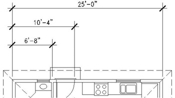
Figure 11.16: An example of baseline dimensions
- Click the Baseline button on the Dimension toolbar. The prompt reads Specify a second extension line origin or [Undo/Select] <Select>:, just like the first prompt for the Continue command.
- Press to choose the Select option.
- Pick the extension line that extends from the upper-left corner—the first extension line of the first dimension.
- Pick the upper-right corner of the walls, and then press Esc to cancel the Baseline command. The overall dimension is drawn above the first two dimensions (see Figure 11.17). (The Baseline command will keep running until you cancel it, just like the Continue command.)
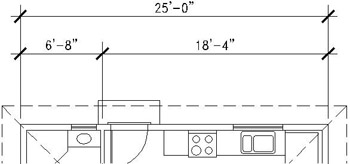
Figure 11.17: The completion of the overall dimension with the Baseline command
The Baseline command assumes the baseline is the first extension line of the last dimension. For the cabin, that would be the extension line that extends to the center of the interior wall. You want the baseline to be the extension line above the upper-left corner of the walls, so press to select that extension line.
It would be nice to have a dimension for the roof spaced the same distance above the overall dimension as the overall dimension is spaced above the incremental dimensions. The Baseline command can help you do this.
- Start the Baseline command again. This time, don’t press . We’ll use the first extension line of the last dimension for our baseline.
- Pick the extension line for the upper-left corner of the walls as the baseline.
- Pick the upper-right corner of the roof. A dimension is placed above the overall dimension (see Figure 11.18a). Press Esc to cancel the Baseline command. To finish it, you need to move the left extension line of this last dimension to the upper-left corner of the roof.
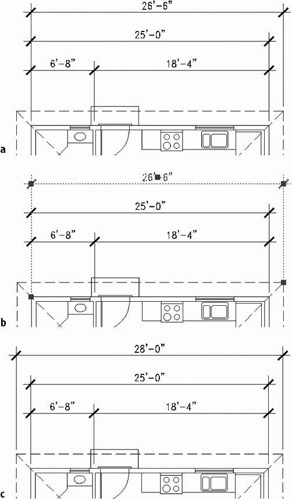
Figure 11.18: The result of the second use of the Baseline command (a), starting grips to modify the dimension (b), and the result (c) - Click the text of the roof dimension. Grips appear in five places on the dimension, and the dimension ghosts (see Figure 11.18b).
- Click the grip at the bottom of the left extension line to activate it.
- Click the upper-left corner of the roof, and then press Esc. The extension line moves, and the dimension text is updated to display the full length of the roof (see Figure 11.18c).
This completes the horizontal dimensions for the back wall.
Vertical Dimensions
Because the Linear command can be used for vertical and horizontal dimensions, you can follow the steps in the previous exercise to do the vertical dimensions on the left side of the floor plan. The only difference from the horizontal dimensioning is that there is no jamb line whose midpoint can be used to establish the center of the interior wall between the bedroom and bathroom. You will draw a guideline—the same one you drew in the last chapter to help make the grid. The following steps will take you through the process of placing the first vertical dimension. You’ll then be able to finish the rest of them by yourself.
- Pan and zoom to get a good view of the left side of the floor plan, including the space between the roof and the border (see Figure 11.19).
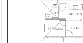
Figure 11.19: The result of zooming and panning for a view of the left side of the floor plan - Draw a guideline between the two horizontal interior wall lines where they meet the exterior wall. Endpoint Osnap should be running, and you should be able to do this without having to zoom in.
You drew the same guideline in Chapter 10 when you drew the structural grid.
- Click the Linear button. Then pick the upper-left corner of the walls.
- Select Midpoint Osnap and move the cursor to the short guideline that you just drew. When the triangle appears on the line (see Figure 11.20a), click. The vertical dimension appears in ghosted form, attached to the cursor.
- Move the dimension line to a point about 3' to the left of the roof line and click. The first vertical dimension is drawn (see Figure 11.20b).
- Erase the short guideline from between the interior walls.
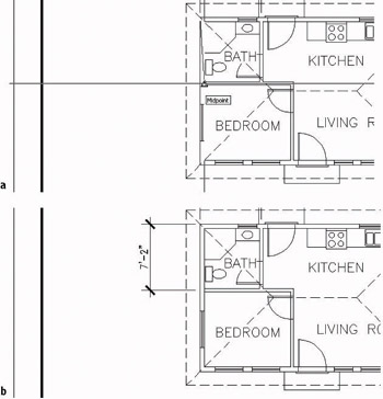
Figure 11.20: A guideline is drawn to help find the center of an interior wall (a), and the first vertical dimension is placed (b).
Finishing the Vertical Dimensions
You place the rest of the vertical dimensions using the procedure you used to complete the horizontal dimensions. Here is a summary of the steps:
- Use the Continue command to dimension the bedroom.
- Use the Baseline command to place an overall dimension.
- Use the Baseline command to place a roof dimension to the left of the overall dimension.
- Use grips to move the first extension line of the roof dimension to its corner.
Look back at the previous section if you need more detailed instructions. The completed vertical dimensions will look like Figure 11.21.
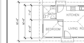
Figure 11.21: The completed vertical dimensions
The next area to dimension is the balcony.
- Pan to a view of the balcony. Include some space below and to the right of it.
Tip When you have a floating toolbar on the screen, using the Zoom Window command doesn’t take into account the area that the floating toolbar takes up. When you can, it’s better to use Realtime Pan and Zoom to adjust your view in this situation.
- Start the Linear command, and pick the lower-right corner of the building walls.
- Use Quadrant Osnap, and pick near the rightmost edge of the outside balcony wall.
- When the dimension appears, move it a couple of feet below the bottom roof line and place it there (see Figure 11.22).
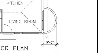
Figure 11.22: The horizontal balcony dimension
This will be enough on vertical and horizontal linear dimensions for now. Let’s take a look at some other kinds of dimensions.
Other Types of Dimensions
AutoCAD provides tools for placing radial and angular dimensions on the drawing and for placing linear dimensions that are neither vertical nor horizontal. You’ll use the Radial command to dimension the inside radius of the balcony.
Radial Dimensions
On the Dimension toolbar are icons for radial and diameter dimensions. They both operate the same way and are controlled by the same settings.

| Tip |
The icons on the toolbars don’t really look like buttons until you move the pointer cursor onto them. In this book, I refer to them as both icons and buttons. |
- Click the Osnap button on the status bar to temporarily disable any running Osnaps.
- Click the Radius Dimension button to start the Dimradius command.
Note Most of the commands used for dimensioning are prefaced with a “dim” when you enter them at the command line, and that is the actual name of the command. For example, when you click the Radius Dimension button on the Dimension toolbar or choose Dimension Radius on the menu bar, you will see _dimradius in the Command window to let you know that you have started the Dimradius command. You can also start this command by typing dimradius or dra (the shortcut alias).
- Click the inside arc of the balcony a slight distance above the midpoint. The radial dimension appears in ghosted form. Its angle of orientation is determined by where you pick the arc. The dimension text then stays attached to the cursor (see Figure 11.23).
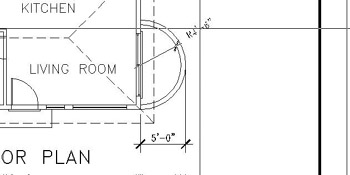
Figure 11.23: The radial dimension initially positioned in the arc - Notice that the tick mark used for linear dimensions is used here also. We must have an arrowhead for the radial dimension. Press Esc to cancel the command.
We will have to alter the dimension style to specify an arrowhead for radial dimensions.
Parent and Child Dimensioning Styles
The DimPlan dimension style that you set up at the beginning of this chapter applies to all dimensions and is called the parent dimension style. But you can change settings in this dimension style for particular types of dimensions, such as the radial type, for example. This makes a child dimension style. The child version is based on the parent version, but has a few settings that are different.
In this way, all your dimensions will be made using the DimPlan dimension style, but radial dimensions will use a child version of the style. Once you create a child dimension style from the parent style, you refer to both styles by the same name, and you call them a dimension style family.
- Click the Dimension Style button on the Dimension toolbar to open the Dimension Style Manager dialog box. It will look like Figure 11.24.
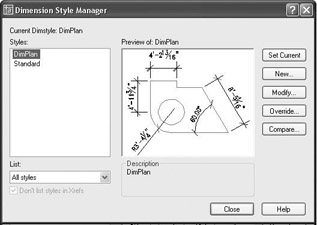
Figure 11.24: The Dimension Style Manager dialog box with DimPlan current - Be sure DimPlan is highlighted in the Styles list, and then click the New button to open the Create New Dimension Style dialog box.
- Open the Use For drop-down list and select Radius Dimensions. Then click the Continue button. The New Dimension Style dialog box opens and has the six tabs you worked with earlier. Its title bar now includes Radial, and the preview window shows a radial dimension.
- Activate the Lines And Arrows tab. Then move to the Arrowheads area and open the second Arrowhead drop-down list.
- Select Right-Angle. Notice how the preview window now illustrates a radial dimension with a right-angle arrowhead.
- Click the Text tab.
- In the Text Placement area, open the Vertical drop-down list and select Centered.
- Click OK to close the New Dimension Style: DimPlan: Radial dialog box.
- In the Dimension Style Manager dialog box, notice the Styles list. Radial is now a substyle of DimPlan. Radial is referred to as a “child” style of the “parent” style DimPlan. Click Close to close the Dimension Style Manager dialog box.
- Click the Radius button on the Dimension toolbar.
- Click the inside arc of the balcony at a point about 15 above the right quadrant point. The radius dimension appears in ghosted form, and it now has an arrow instead of a tick mark.
- Move the cursor to the outside of the balcony, and place the dimension text so that it looks similar to Figure 11.25.
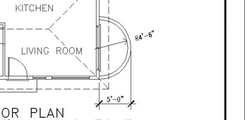
Figure 11.25: The radius dimension for the balcony
When placing the radial dimension, you have control over the angle of the dimension line (by where you pick the arc) and the location of the dimension text (by where you pick the second point).
The balcony also needs to be given a name in the drawing, like the other rooms.
Leader Lines
Use the Leader command to draw an arrow to the balcony and place the text outside the arcs. Before you do that, you need to adjust a few dimension style settings for the leader dimension.
- Click the Dimension Style button on the Dimension toolbar.
- With DimPlan highlighted, click New.
- In the Create New Dimension Style dialog box, open the Use For drop-down list and click Leaders And Tolerances. Then click Continue.
- Activate the Lines And Arrows tab, move to the Arrowheads area, and open the Leader drop-down list. Click Right-Angle.
- Click the Text tab. In the Text Placement area, change Above to Centered. Then click OK.
Tip If you want the Balcony label text in the same text style as the room labels, you can change the Text Style in the Text Appearance area of the Text tab to the Label text style.
- Notice how Leader is now a child style, along with Radial, in the Styles list. Click Close. Another child DimPlan dimension style is created that is identical to the regular DimPlan style except for the two settings that you just changed.
- Click Close to close the Dimension Style Manager, and then click the Quick Leader button on the Dimension toolbar.
- Click the Osnap button in the status bar to temporarily disable running Osnaps, if it’s not already in the off position.
- Pick a point inside the balcony just below the radial dimension line.
- Drag the line to the outside of the balcony, making the line approximately parallel to the radial dimension line, and pick a point (see Figure 11.26a).
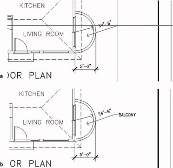
Figure 11.26: The leader line being drawn (a), and the completed leader (b) - Press . Then, at the Specify text width <0">: prompt, press again. At the next prompt, with Caps Lock on, type balcony. The prompt changes to read Enter next line of annotation text:. Now you can enter multiple lines of text for the leader. Press . The leader is completed, and the word BALCONY is placed at the end of the leader line (see Figure 11.26b).
Note If the angle of the leader line is steeper than 15, a short horizontal line called a dogleg or hook line is added between the leader line and the text.
- Zoom to Extents, and then zoom out a little and pan to view the whole drawing with dimensions.
- Save this drawing as Cabin11a.
This exercise got you started using the Leader command. Later in this chapter, in the section on modifying dimensions, you will get another chance to work with leader lines and their text. Next, I will introduce you to two more types of dimensions.
Angular and Aligned Dimensions
To get familiar with the aligned and angular dimension types, play around with the two commands, using the roof lines to experiment. Here’s how to set up Cabin11a to work with aligned and angular dimensions:
- Type undo, and then type m.
- Make the Roof layer current.
- Turn off all other layers by following these steps:
- Click the Layers button.
- In the Layer Properties Manager dialog box, place the cursor anywhere on the list of layer names and right-click to open a small menu.
- Choose Select All But Current on the menu. Then click one of the light bulbs for any highlighted layer in the On column.
- The light bulbs for all selected layers turn off, indicating that those layers have been turned off.
- Click OK to close the dialog box and return to the drawing. Everything has disappeared except the roof lines.
- Pan and zoom to get a closer view of the roof.
- Create a new layer called Dim2. Accept the color that is assigned to it, and make Dim2 current.
- Set Endpoint Osnap to be running. Now you are ready to dimension.
Aligned Dimensions
Aligned dimensions are linear dimensions that are not horizontal or vertical. You place them in the same way that you place horizontal or vertical dimensions with the Linear command. You can also use the Baseline and Continue commands with aligned dimensions.
Use the Aligned command to dimension a hip line of the roof. Try it on your own. Follow the prompts. It works just like the Dimlinear command, except that the dimension is not displayed on the drawing until you finish the command.
Start the Aligned command by clicking the Align button on the Dimension toolbar. Look ahead to Figure 11.27 to see the results you should get.
Angular Dimensions
The angular dimension is the only basic dimension type that uses angles in the dimension text instead of linear measurements. Generally, tick marks are not used with angular dimensions, so you need to create another child dimension style for this type of dimension. Follow the steps given earlier in this chapter for setting up the Radial and Leader child styles. The only change you need to make is on the Lines And Arrows tab: replace the Architectural tick with the Right-Angle arrowhead.
Try making an angular dimension on your own. You can start the Angular command by clicking the Angular button on the Dimension toolbar. Follow the prompts and see if you can figure out how this command works.
Figure 11.27 illustrates angular and aligned dimensions on the roof.
Figure 11.27: The roof with angular and aligned dimensions
Don’t save your drawing as is. Instead, type undo, and then type b. This will undo the angular and aligned dimensions you just created and the Dim2 dimension style and leave your drawing at the state it was in when you last saved it as Cabin 11a.
When you change settings for a dimension style, dimensions created when that style was current will be automatically updated to reflect the changes. You’ll modify more dimensions in the next section.
You have been introduced to the basic types of dimensions—linear, radial, leader, and angular—and some auxiliary dimensions—baseline, continue, and aligned—that are special cases of the linear type. The baseline and continue dimensions can also be used with angular dimensions.
Ordinate Dimensions
Ordinate dimensions are widely used by the mechanical and civil engineering professions and related trades. They differ from the kind of dimensioning we have been doing so far in this chapter in that ordinate dimensioning specifies X and Y coordinate values for specific points in a drawing based on an absolute or relative Cartesian coordinate system, rather than on a distance between two points. This method is used to dimension centers of holes in sheet metal or machine parts and to locate surveying points on an area map.
We don’t need ordinate dimensions in our cabin project, so we will go through a quick exercise in setting them up to dimension the holes in a plate. This will give you a glimpse of the tools that AutoCAD provides for working with them. If you are not interested in ordinate dimensioning, move on to the next section on modifying the dimensions we’ve already created for the cabin.
- Open a new drawing, and leave the units at the default of Decimal with a precision of four decimal places. Set Polar Tracking to be on.
- Set up a new text style called Arial; select Arial as the font and 0.125 as the height. Click Apply & Close to make it the current text style.
- Draw a rectangle using 0,0 as the first point and 6,–4 as the second.
- Zoom to Extents, and then zoom to .5x. Turn off the UCS icon.
- Draw a circle somewhere in the upper-left quadrant of the rectangle with a radius of 0.35 units; then, using Polar Tracking, copy that circle once directly to the right and once directly below the original and to two other locations not aligned with any other circle, so the configuration looks something like Figure 11.28a.
- Set Endpoint and Center Osnaps to be running.
What we care about with ordinate dimensioning is not how far apart the holes are from each other, but how far the X and Y coordinates of the centers of the holes are away from some reference point on the plate. We’ll use the upper-left corner of the plate as our reference point, or datum point, because it is positioned at the origin of the drawing, or at the 0,0 point.
- Click the Ordinate button on the Dimension toolbar.
- Click the upper-left corner of the rectangular plate, and then move the cursor straight up above the point you picked. When you are about an inch above the plate, click again. This sets the first ordinate dimension (see Figure 11.28a).
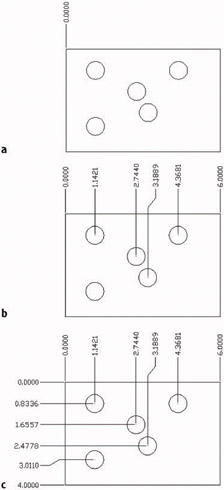
Figure 11.28: Placing the first ordinate dimension (a), finishing up the X coordinate dimensions (b), and placing the Y coordinate dimensions (c) - Repeat step 8 for the four circles near the middle or upper portions of the plate, using their centers as points to snap to and aligning the ordinate dimensions by eye. The lower circle is in vertical alignment with the one above it, so it needs no horizontal dimension. Place an ordinate dimension on the upper-right corner of the plate to finish up. The result will look like Figure 11.28b. Note that one of the extension lines has a jog in it for spacing. You will see that this is an option for each ordinate dimension you place.
- Repeat this procedure for the y ordinate dimensions. Once again, ignore any circles that are in vertical alignment, but include the upper- and lower-left corners of the plate (see Figure 11.28c).
In civil engineering, ordinate dimensions are used almost the same way, but displayed differently. A datum reference point is used, but the dimensions are displayed at each point. This is because the points are a set of surveying points spread randomly over a large area, and the datum or reference point may be miles away (see Figure 11.29).
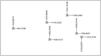
Figure 11.29: A sample surveyor’s datum points with ordinate dimensions
The final part of this chapter will be devoted to teaching you a few techniques for modifying dimensions.
Modifying Dimensions
You can use several commands and grips to modify dimensions, depending on the desired change. You can:
- Change the dimension text content.
- Move the dimension text relative to the dimension line.
- Move the dimension or extension lines.
- Change the dimension style settings for a dimension or a group of dimensions.
- Revise a dimension style.
The best way to understand how to modify dimensions is to try a few.
Modifying Dimension Text
You can modify any aspect of the dimension text. We’ll look at how to change the content first.
Editing Dimension Text Content
To change the content of text for one dimension, or to add text before or after the actual dimension, use the Ddedit command. (You used this command in Chapter 10 to modify text.) We’ll change the text in the horizontal dimensions for the roof and walls.
- Zoom and pan until your view of the floor plan is similar to Figure 11.30.
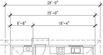
Figure 11.30: A modified view of the floor plan - Type ddedit. Then select the horizontal roof dimension at the top of the drawing. The Multiline Text Editor window and the Text Formatting toolbar appear. The angle brackets in the editing window represent the existing text in the dimension, 28'-0". You can highlight the brackets and enter a new dimension or enter new text before or after the brackets.

- Click to the right of the brackets, press the spacebar to create a space, type verify in field, and click OK on the right end of the toolbar. The phrase is added to the dimension (see Figure 11.31a). The prompt tells you that you can select another object to edit.
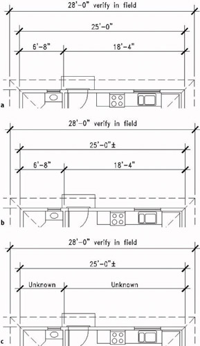
Figure 11.31: Adding a phrase to dimension text (a), adding a special character (b), and editing more than one dimension text at a time (c) - Click the dimension just below the roof dimension.
- In the Multiline Text Editor window, click to the right of the angle brackets again. Then right-click, and choose Symbol from the shortcut menu to open a flyout.
- Select Plus/Minus. The symbol is now in the edit window.
- Click OK. The dimension now has a after it (see Figure 11.31b). Press to end the Ddedit command.
If you need to change the text of several dimensions at once, use the Dimedit command.
- Click the Dimension Edit button on the Dimension toolbar.
- At the Enter type of dimension editing [Home/New/Rotate/Oblique] <Home>: prompt, type n to replace the existing text or to add to it.
- In the Multiline Text Editor dialog box, highlight the angle brackets.
- Type Unknown and click OK.
- In the drawing, click the 6'-8" and 18'-4" dimensions. Then press .
- The two dimensions now read Unknown (see Figure 11.31c).
Next, you’ll learn about moving a dimension.
Moving Dimensions
You can use grips to move dimensions. We used grips to move the extension line of the roof dimension when we were putting on the vertical and horizontal dimensions. This time we’ll move the dimension line and the text.
- Zoom in to a view of the right side of the floor plan until you have a view that includes the entire balcony and its three dimensions, as well as the entire right cabin wall.
- At the Command: prompt, click the 5'-0" dimension. Grips appear.
- Click the grip on the right tick mark to activate it.
- Move the cursor up until the dimension text is above the balcony. Then click again to fix it there. Click the grip that’s on the text, and with Polar Tracking on, move the text slightly to the right to clear it from the roof line. Then press Esc (see Figure 11.32a). The dimension, line, and text move to a new position, and the extension lines are redrawn to the new position.
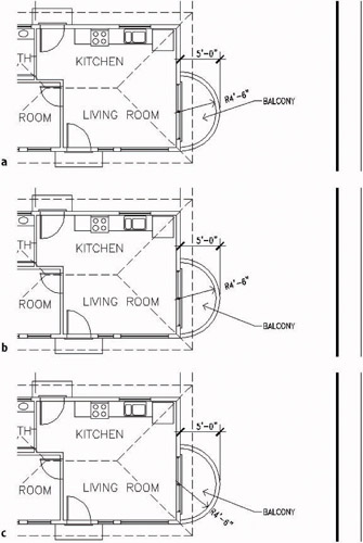
Figure 11.32: Moving the balcony dimensions with grips: the Linear dimension (a), the leader (b), and the Radial dimension (c) - Click the leader line. Then click the word BALCONY. Two grips appear on the leader line, and one appears on the text.
- Hold down the Shift key and click the two grips near the text. Then release the Shift key.
- Click one of the two activated grips. Move the cursor down to reposition the leader and text slightly below the Quadrant point of the balcony arcs. Then click to fasten them there. Press Esc (see Figure 11.32b).
- Be sure Osnap is turned off, and then click the 4'-6" radial dimension. Three grips appear.
- Click the grip at the arrowhead.
- Move the cursor to the inside arc and below the just-relocated leader line until the Radial dimension line and its text display in a clear space. Pick that point.
- Press Esc (see Figure 11.32c).
To finish the changes to the balcony, you need to suppress the left extension line of the 5'-0" dimension because it overlaps the wall and header lines.
Dimension Overrides
You suppress the left extension line with the Properties command, which allows you to change a setting in the dimension style for one dimension without altering the style settings.
- Turn off the Headers layer.
- Click the Properties button on the Standard toolbar. If necessary, drag the Dimensioning toolbar far enough to the right to clear the Properties palette.
- Click the 5'-0" dimension.
- In the Properties palette, move to the Lines And Arrows heading. If this section is not open, click the double arrows to the right.
- Scroll down the list of settings in this section and click Ext Line 1. Then click the down arrow in the right column to open the drop-down list. Click Off. The left extension line on the linear balcony dimension is suppressed.
- Close the Properties palette. Press Esc to remove the grips (see Figure 11.33).
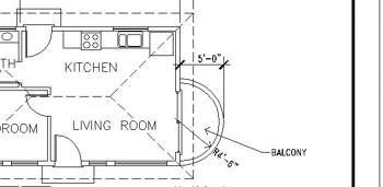
Figure 11.33: The 5'-0" dimension with the left extension line suppressed
The bedroom needs a horizontal dimension. Because space outside the floor plan is tight, you’ll place the dimension inside the bedroom and suppress both extension lines with an override to the current dimension style.
- Pan the drawing over until the bedroom is fully in view.
- Open the Dimension Style Manager dialog box and click the Override button.
- Activate the Lines And Arrows tab. In the Extension Lines area, move to the bottom where it says Suppress, and put a check mark in the Ext Line 1 and Ext Line 2 check boxes. Then click OK.
- In the Dimension Style Manager dialog box, click Close.
- Click the Linear button on the Dimension toolbar.
- Activate running Osnaps. In the bedroom, pick the lower-left inside corner, and then pick the lower-right inside corner. The dimension appears in ghosted form, attached to the cursor.
- Suppress the running Osnaps for one pick. Then move the dimension up to a position below the BEDROOM text and above the lower wall, and click to fix it there. The dimension is placed, and both extension lines are suppressed (see Figure 11.34).
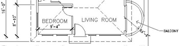
Figure 11.34: The completed bedroom dimension - Open the Dimension Style Manager dialog box. In the Styles list, the current style is the substyle under DimPlan called
Introduction
- Getting to Know AutoCAD
- Basic Commands to Get Started
- Setting Up a Drawing
- Gaining Drawing Strategies: Part 1
- Gaining Drawing Strategies: Part 2
- Using Layers to Organize Your Drawing
- Grouping Objects into Blocks
- Generating Elevations
- Working with Hatches and Fills
- Controlling Text in a Drawing
- Dimensioning a Drawing
- Managing External References
- Using Layouts to Set Up a Print
- Printing an AutoCAD Drawing
- Appendix A Look at Drawing in 3D
EAN: N/A
Pages: 159
