Controlling Text in a Drawing
Controlling Textin a Drawing
Overview
- Setting up text styles
- Placing new text in the drawing
- Modifying text in a drawing
- Working with grid lines
- Managing single-line and multiline text
- Creating a table
You will have many uses for text in your drawings, including titles of views, notes, and dimensions. Each of these may require a different height, orientation, and style of lettering. To control the text, you will need to learn three basic operations:
- Determine how the text will look by setting up text styles.
- Specify where the text will be and enter it into the drawing.
- Modify the text already in your drawing.
AutoCAD offers two types of text objects: single-line and multiline. Single-line text makes a distinct object of each line of text, whether the line is one letter or many words. This type of text is useful for titles of drawings, titles of views within a drawing, room labels, and schedules. Dimensions, tables, and longer notes are done with multiline text. AutoCAD treats a whole body of multiline text as one object, whether the text consists of one letter or many paragraphs.
The two types of text share the same text styles, but each has its own command for placing text in the drawing. When you modify text, you can use the same commands for either type of text, but the commands operate differently for multiline than for single-line text. Any text used in dimensioning—a process by which you indicate the sizes of various components in your drawing—is handled slightly differently from other text and will be covered in Chapter 11.
We will progress through this chapter by first looking at the process of setting up text styles. We will then start placing and modifying single-line text in the cabin drawing. Finally, we’ll look at the methods for creating and controlling multiline text as it is used for notes and tables. If you work in a non-AEC profession or trade, be assured that the features presented in this chapter will apply directly to your work. The basic principles of working with text in AutoCAD and AutoCAD LT “cross the curriculum” (an educational metaphor) and apply universally.
Setting Up Text Styles
In AutoCAD, a text style consists of a combination of a style name, a text font, a height, a width factor, an oblique angle, and a few other, mostly static settings. You specify these text style properties with the help of a dialog box that opens when you start the Style command. You will begin by setting up two text styles—one for labeling the rooms in the floor plan and the other for putting titles on the two views. You will need a new layer for text.
- Open the Cabin09c drawing.
- Create a new layer named Text1. Assign it a color, and make it current.
- Freeze the Hatch-plan-floor and Hatch-plan-wall layers. Be sure all other layers are thawed and turned on. Your drawing should look like Figure 10.1.
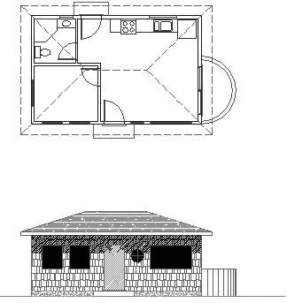
Figure 10.1: The Cabin09c drawing with the Hatch-plan-floor and Hatch-plan-wall layers frozen
Text and Drawing Scale
When you set up text styles for a drawing, you have to determine the height of the text letters. To make this determination, you first need to decide the scale at which the final drawing will be printed.
In traditional drafting, you can ignore the drawing scale and set the actual height of each kind of text. This is possible because, while the drawing is to a scale, the text doesn’t have to conform to that scale and is drawn full size.
In AutoCAD, a feature called layouts makes it possible to set the height of text in the same way—that is, at the height at which it will be printed. You will learn about using layouts in Chapter 13. In that chapter, you’ll place text on layouts; in this chapter, I’ll demonstrate how text is used without layouts. You’ll place text in the cabin drawing. The drawing is actual size, but the text has to be much larger than actual size because both the drawing and its text will be scaled down by the same factor in the process of printing the drawing.
A layout is a drawing environment that has been overlaid on the drawing of your project. The layout and the drawing are part of the same file.
In this drawing, we will use a final scale of 1⁄8" = 1'-0". This scale has a true ratio of 1:96 and a scale factor of 96. (See Table 9.1 in Chapter 9.) If you want text to be 1⁄8" high when you print the drawing at 1⁄8-inch scale, multiply 1⁄8" by the scale factor of 96 to get 12" for the text height. You can check that calculated text height by studying the floor plan for a moment and noting the sizes of the building components represented in the drawing. You can estimate that the room label text should be about half as high as the front step is deep, or 1 foot high.
Defining a Text Style for Room Labels
Now that you have a good idea of the required text height, it’s time to define a new text style. Each new AutoCAD .dwg file comes with one predefined text style named Standard. You will add two more.
- Type st to start the Style command and open the Text Style dialog box (see Figure 10.2). In the Style Name area, you will see the default Standard text style.
You can also start the Style command by choosing Format Text Style.
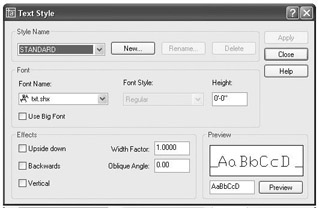
Figure 10.2: The Text Style dialog box, in which text styles are set up - Click New to open the New Text Style dialog box. There is a Style Name text box with style1 in it, highlighted. When you enter a new style name, it will replace style1.
By default, all new .dwg files have the Standard text style as the current text style.
- Type Label. The New Text Style dialog box closes, and in the Text Style dialog box, Label appears in the Style Name drop-down list. You have created a new text style named Label. It has settings identical to those of the Standard text style, and it is now the current text style. Now you will change some of the settings for this new style.
- Move down to the Font area and click the Font Name drop-down list to open it. A list of fonts appears; the number of choices depends on what software is installed on your computer.
A font is a collection of text characters and symbols that all share a characteristic style of design and proportion.
- Scroll through the list until you find romans.shx, and then click it. The list closes, and in the Font Name text box, the romans.shx font replaces the txt.shx font that was previously there. In the Preview area in the lower-right corner, a sample of the romans.shx font replaces that of the txt.shx font.
- Press the Tab key to jump to the next text box. The Height setting is highlighted at the default of 0'-0".
- Type 12, and then press Tab again. A height of 1'-0" replaces the default height.
- You won’t need to change any of the other parameters that define the new text style. They can all stay at their default settings.
- Click Apply in the upper-right corner of the dialog box. The Label text style is saved with the current drawing and becomes the current text style.
Note The current text style is similar to the current layer. All text created while a text style is current will follow the parameters or settings of that text style.
When you define a new text style, you first name the new style. This has the effect of making a copy of the current text style settings, giving them the new name, and making the new text style current. You then change the settings for this new style and save the changes by clicking Apply.
Defining a Second Text Style
Before you close the dialog box, define another text style.
- Click New.
- In the New Text Style dialog box, type Title and click OK. A new text style called Title has been created and is now the current text style. Its font, height, and other settings are a copy of the Label text style. Now you will make changes to these settings to define the Title text style.
- Click the current font, romans.shx. The drop-down list of fonts opens. Scroll up one font and click romand.shx. The list closes, and romand.shx is displayed as the chosen font.
Romans.shx and romand.shx are frequently used fonts in AutoCAD. Romans (formally named roman simplex) is usually applied to notes in the drawing. Romand (duplex) is a boldface version of romans and can be used for titles of views, titles of details, and dimensioning. Two more fonts in the roman font family—romanc and romant—are used for larger text.
- Press Tab once to move to the Height text box, type 18, and then press Tab once more. The height is converted to 1'-6".
Tip If you press after typing the height, the new style is automatically applied, meaning it is saved and made the current text style. Don’t do this if you need to change other settings for the style.
- Click Apply, and then click Close.
Of the many fonts available in AutoCAD, you will use only a few for your drawings. Some are set up for foreign languages or mapping symbols. Others would appear out of place on architectural or technical drawings, but might be just right for an advertising brochure or a flier. Later in this chapter, you’ll have a chance to experiment with the available fonts.
Look back at Figure 10.2 for a moment, and note that the Standard text style has a height of 0'-0". When the current text style has a height set to 0, you are prompted to enter a height each time you begin to place single-line text in the drawing. The default height will be 3⁄16" (or 0.20 for decimal units and 2.5 for metric). Multiline text will use the default height of 3⁄16" unless you change it.
Now that you have two new text styles, you can start working with single-line text.
Using Single Line Text
Your first task is to put titles in for the floor plan and front elevation, using the new Title text style.
Placing Titles of Views in the Drawing
The titles need to be centered approximately under each view. If you establish a vertical guideline through the middle of the drawing, you can use it to position the text.
- Pan the drawing up to create a little more room under the front elevation.
- Set up your Osnaps and status bar such that Polar and Osnap are on and Endpoint and Midpoint Osnaps are running. Drop a line from the midpoint of the ridgeline in the floor plan, down through the front elevation, to a point near the bottom of the screen.
- Offset the bottom line of the front step in the floor plan down 4'.
- Choose Draw Text Single Line Text to start the Dtext command—the command used for single-line text.
You can also start the Dtext command by typing dt.
- The bottom line of text in the Command window reads Specify start point of text or [Justify/Style]:. The line above it displays the name of the current text style and the style’s height setting. The bottom line is the actual prompt, with three options. By default, the justification point is set to the lower-left corner of the text. You need to change it to the middle of the text to be able to center it on the guideline.
- Type j. All the possible justification points appear in the prompt.
- Type c to choose Center as the justification.
The justification point for the text functions like the insertion point for blocks.
- Hold down the Shift key and right-click to open a menu of Osnap options next to where the cursor had just been positioned.
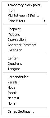
The Osnap Cursor menu (Shift+right-click) contains all the Object Snap tools, access to the Osnap Settings dialog box to allow you to set running Osnaps, and a Point Filters menu.
- Choose Intersection and pick the intersection of the guideline and the offset line.
- For the rotation, press to accept the default angle of 0. An I cursor will be positioned at the intersection (see Figure 10.3).
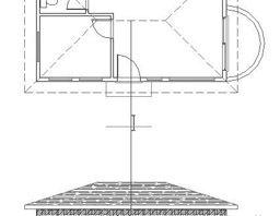
Figure 10.3: The text cursor sits on the guidelines. - With Caps Lock on, type floor plan. The text is at the intersection as you type it (but not centered yet), and the cursor jumps down to allow you to type another line (see Figure 10.4a).
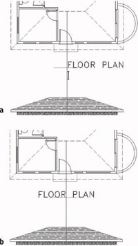
Figure 10.4: The first line of text is entered (a) and placed (b). - Press again to end the Dtext command. The text is centered relative to the vertical guideline and sits on the offset line (see Figure 10.4b).
- Offset the ground line of the elevation down 4'. Start the Dtext command again, and repeat steps 4 through 12, this time entering front elevation (again with Caps Lock on). When finished, erase the offset lines and the vertical guideline. Your drawing will look like Figure 10.5.
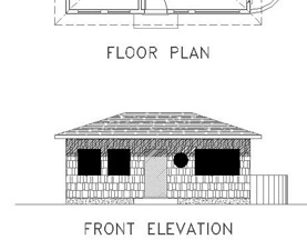
Figure 10.5: The drawing with the titles complete
You specified a location for the text in two steps: first, you set the justification point of each line of text to be centered horizontally; then you used the Intersection Osnap to position the justification point at the intersection of the two guidelines. I’ll discuss justification in more depth a little later in this chapter.
Next you will move to the interior of the cabin floor plan and place the room labels in their respective rooms.
Placing Room Labels in the Floor Plan
Text for the room labels will use the Label text style, so you need to make that style current before you start placing text. You can accomplish this from within the Dtext command by using the Style option.
- Pan down the drawing and zoom in to the floor plan. Click the Polar and Osnap buttons on the status bar to turn off these features.
- Start the Dtext command. At the prompt, type s to choose the Style option. The prompt reads Enter style name or [?] <Title>:.
- Type ? to see a list of defined text styles. In the text screen, you see Label, Standard, and Title listed along with information about the parameters of each style (see Figure 10.6). At the bottom of the text screen, you can see the Dtext prompt again.
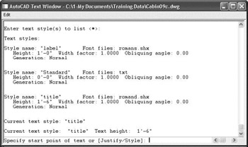
Figure 10.6: The text screen listing the defined text styles - Type s again. Then type label to make Label the current text style.
- Press F2 to close the text screen and return to the drawing.
- Pick a point in the kitchen a couple of feet below and to the left of the oven.
- Press at the Rotation prompt. The text cursor appears at the point you picked.
- With Caps Lock on, type kitchen living room bedroom bath. The Dtext command ends. You will have four lines of text in the kitchen and living room area (see Figure 10.7).
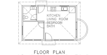
Figure 10.7: The four room labels placed in the cabin
For this text, you used the default Left justification, and each line of text was positioned directly below the previous line at a spacing set by AutoCAD. In many cases, it is more efficient to type a list of words or phrases first and then move the text to its appropriate location. That’s what we are doing for this text.
Moving Text
We will eyeball the final position of this text because it doesn’t have to be exactly centered or lined up precisely with anything. It should just sit in the rooms in such a way that it is easily readable.
- Click anywhere on the BATH text. One grip appears, at the justification point of the text.
- Click the grip to activate it. The BATH text is attached to the cursor and moves with it (see Figure 10.8a). The Stretch command automatically starts. Because text can’t be stretched, the Stretch command functions like the Move command.
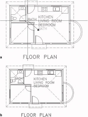
Figure 10.8: Moving the BATH text (a), and its new location (b) - Be sure that Ortho, Polar, Osnap (and, for AutoCAD only, Otrack) are turned off. Move the cursor to the bathroom, and click a location to place the word in such a way that the letters—while they may be on top of the door swing and the roof line—don’t touch any fixtures or walls.
- Press Esc to remove the grip (see Figure 10.8b). Then select the BEDROOM text.
- Click the grip for the newly selected text.
- Pick a point in the bedroom so that the BEDROOM text is positioned approximately at the center of the bedroom and crossing only the roof line. Press Esc to remove the grip.
When you move text in this way, you are actually using the Stretch command. Because text can’t be stretched, it just moves with the cursor.
- Repeat this process to move the LIVING ROOM and KITCHEN text into their appropriate locations (see Figure 10.9). You may not have to move the KITCHEN text.
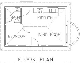
Figure 10.9: The BEDROOM, LIVING ROOM, and KITCHEN text moved to their positions
As you have seen, you can easily move text around the drawing. Often, however, you will be unable to position it without it sitting on top of a line or other object. In the cabin, three of the room labels are crossing the roof line, and BATH is crossing a door swing. You need to erase parts of these lines around the text. To do this, you’ll use the Break command.
Breaking Lines
The Break command chops a line into two lines. When working with text that is sitting on a line, you will usually want a gap between the lines after the break. The Break command provides this option as well as others.
- Be sure no Osnaps are running, and then click the Break button on the Modify toolbar.
You can also start the Break command by choosing Modify Break or by typing br.
- Move the cursor near the roof line that crosses through the LIVING ROOM text. Place the pickbox on the roof line just above the text and click. The line ghosts, and the cursor changes to the crosshair cursor.
- Put the crosshair cursor on the roof line just below the text and pick that point. The line is broken around the text, and the Break command ends.
- Press to restart the Break command, and do the same operation on the roof line that crosses the BEDROOM text.
- Press again, and break the roof line around the BATH text. The arc representing the door swing is part of the door2_6 block and, as such, cannot be broken. You must explode the block to be able to break the arc.
- Click the Explode button on the Modify toolbar, and then select the bathroom door. Then press . The door2_6 block is exploded.
- Zoom in closer to the bathroom. Start the Break command, and select two points on the arc to break it around the BATH text. Zoom Previous to get a full view of the floor plan (see Figure 10.10).
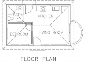
Figure 10.10: Lines are broken around the room labels.
A Closer Look at the Break Command
Use your own judgment to determine how far from the text a line has to be broken back. You have to strike a balance between making the text easy to read and keeping what the broken line represents clear. In the bathroom, you were directed to keep the text away from any fixtures because if any lines of the fixtures had to be broken to accommodate the text, this might have made it difficult for a viewer to recognize that those lines represent a shower or a toilet.
Here are some other options for the Break command:
- Normally, when you select a line to be broken, the point where you pick the line becomes the beginning of the break. If the point where the break needs to start is at the intersection of two lines, you must select the line to be broken somewhere other than at a break point. Otherwise, AutoCAD won’t know which line you want to break. In that case, after selecting the line to break, type f. You will be prompted to pick the first point of the break, and the command continues. Now that AutoCAD knows which line you want to break, you can use Intersection Osnap to pick the intersection of two lines.
- To break a line into two segments without leaving a gap, click the Break At Point button, which is just above the Break button. You might want to do this to place one part of a line on a different layer from the rest of the line. To break the line this way, start the command, select the line to break, and then pick the point on the line where the break is to occur, using an Osnap if necessary. AutoCAD will make the break and end the command.
- When you create a gap in a line for text, the line will have a gap in it even when the text layer is turned off. This will be a problem for the bath door swing and the roof line. We’ll attend to this issue in the last few chapters of this book.
Using Text in a Grid
AutoCAD provides a grid of dots, which you worked with in Chapter 3. The grid is a tool for visualizing the size of the drawing area and for drawing lines whose geometry conforms to the spacing of the dots. Many floor plans have a separate structural grid, created specifically for the project and made up of lines running vertically and horizontally through key structural parts of the building. At one end of each grid line, a circle or a hexagon is placed, and a letter or number is centered in the shape to identify it. This kind of grid is usually reserved for large, complex drawings, but we will put a small grid on the cabin floor plan to learn the basic method for laying one out.
- Create a new layer called Grid. Assign it a color, and make it current.
- Type z . 6x to make more room around the floor plan.
- Offset the upper roof line up 10'. Offset the left roof line 10' to the left. Offset the lower roof line down 2'. Offset the right roof line to the right 4'. Pan and zoom as necessary.
- Set Endpoint and Perpendicular Osnaps to be running, and then start the Line command.
- Draw lines from the upper-left and upper-right corners of the exterior walls up to the horizontal offset line. Then draw lines from the left upper and lower corners of the exterior walls to the vertical offset line on the left (see Figure 10.11).
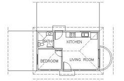
Figure 10.11: The first grid lines - Now you need to draw grid lines through the middle of the interior walls. Zoom in to the bathroom area, and draw a short guideline across the interior wall between the bathroom and bedroom, where this wall meets the exterior wall (see Figure 10.12).
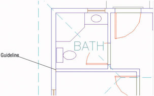
Figure 10.12: A guideline for drawing a grid line through one of the interior walls - Use Realtime Zoom and Pan to set up the view so that it contains the bathroom and the offset roof lines above and to the left of the floor plan.
- Draw two vertical lines and one horizontal line from the middle of the interior walls out to the offset roof lines. Use Midpoint Osnap and pick one of the jamb lines or the guideline to start each line from the middle of a wall (see Figure 10.13).
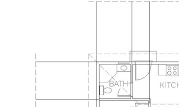
Figure 10.13: Drawing the grid linesTip If Midpoint Osnap were running, it would be difficult to pick the midpoint of the little guideline because Endpoint would have been running too. When you select Midpoint from the Object Snap toolbar, you cancel all running Osnaps for the next pick.
- Erase the guideline you drew in step 6, and then zoom out to a view that includes the floor plan, the grid lines, and all the offset roof lines (see Figure 10.14a).
- Use the Extend command to extend the seven grid lines to the right or down, and use the offset roof lines on those sides of the floor plan as boundary edges (see Figure 10.14b).
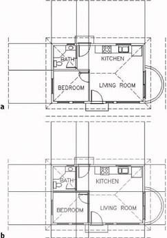
Figure 10.14: The zoomed view for completing the grid lines (a), and the completed grid lines (b)Tip When erasing the guideline, select it with a regular selection window.
This completes the grid lines. To finish the grid, you need to add a circle with a letter or a number in it to the left or upper end of the lines. We’ll use letters across the top and numbers running down the side.
- Erase the four offset roof lines. Zoom out a little.
- Choose Draw Circle 2 Points, and then pick the upper end of the leftmost vertical grid line.
- Type @2'<90. A circle 2' in diameter is placed at the top of the grid line (see Figure 10.15a).
- Click the KITCHEN text. A grip will appear.
- Click the grip and type c, for copy, and press .
- Select the Center Osnap and click the circle on the grid. The KITCHEN text is placed on the circle with the lower-left corner of the text at the center of the circle (see Figure 10.15b). Press Esc twice, once to end the Stretch command and again to clear the grip.
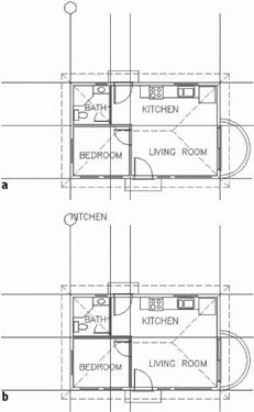
Figure 10.15: The circle on the grid line (a), and the KITCHEN text copied to the circle (b) - Click the copy of the KITCHEN text that is now on the grid, and then click the Properties button on the Standard Properties toolbar to open the Properties palette. Text is displayed on the drop-down list at the top, telling you that you have selected a text object.
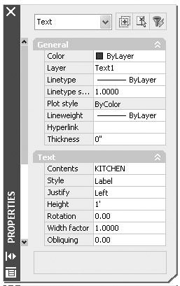
- Use the Properties palette to change the KITCHEN text as follows:
- Change the Layer from Text1 to Grid.
- Change the Contents from KITCHEN to the letter A.
- Change the Justify setting from Left to Middle.
This may seem like a roundabout way to generate letters for the grid symbols, but this exercise is meant to show you how easy it is to use text from one part of the drawing for a completely different text purpose. It’s a handy technique, as long as you want to use a font that has been chosen for a previously defined text style. A faster way to do this is to use the Single Line Text command with the justification set to Middle, use Center Osnap to place the text cursor at the center of the circle, and then type A.
For each change, follow these steps in the Properties palette:
- Click the category in the left column that needs to be changed. If the setting is on a drop-down list, an arrow will be displayed in the right column.
- Click the Down arrow to open the list. In the case of the KITCHEN text, just highlight it, because there is no drop-down list.
- Click the new setting, or type it.
- When finished, close the Properties palette and press Esc to remove the grip.
The KITCHEN text changes to the letter A, is centered in the grid circle, and moves to the Grid layer (see Figure 10.16).
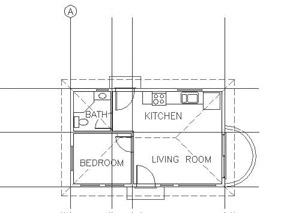
Figure 10.16: The grid circle with the letter A
You used the Center Osnap on the KITCHEN text to position its justification point at the center of the circle. You then modified the justification point from the Left position (which is actually short for Lower Left) to the Middle position (short for Center Middle). The Middle position is the middle of the line of text, horizontally and vertically. So what we did had the effect of centering the text in the circle. Let’s look at Text Justification briefly.
Text Justification
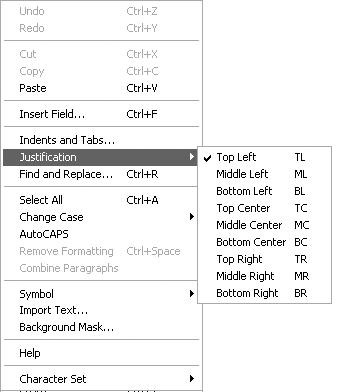
Each line of single-line text is an object. It has a justification point, which is similar to the insertion points on blocks. When drawing, you can use the Insert Osnap to precisely locate the justification point of text (or the insertion point of blocks) and thereby control the text’s position on the drawing. When you use the Dtext command, the default justification point is the lower-left corner of the line of text. At the Dtext prompt (Specify start point of text or [Justify/Style]:), if you type j, you get the prompt Enter an option [Align/Fit/Center/Middle/Right/TL/TC/TR/ML/MC/MR/BL/BC/BR]:. These are your justification options.
Most of these options are represented in Figure 10.17. The dots are in three columns—left, center, and right—and four rows—top, middle, lower, and base. The names of the justification locations are based on these columns and rows. For example, you have TL for Top Left, MR for Middle Right, and so on. The third row down doesn’t use the name Lower. It simply goes by Left, Center, and Right. Left is the default justification position, so it’s not in the list of options. The Middle position will sometimes coincide with the Middle Center position, but not always. For example, if a line of text has descenders—lowercase letters that drop below the base line—the Middle position will drop below the Middle Center position. Finally, the lowest row, the Base row, sits just below the letters at the lowest point of any descenders.
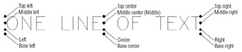
Figure 10.17: The justification points on a line of text
Finishing the Grid
To finish the grid, you need to copy the grid circle with its text to each grid line and then change the text.
- Be sure Endpoint Osnap is still running. Then, at the Command: prompt, select the letter A, and then click the circle. Grips appear.
- Click the grip at the bottom of the circle to activate it.
- Right-click and choose Move; then right-click again and choose Copy to activate the copy option.
- Pick the top end of each vertical grid line; then right-click and choose Enter (see Figure 10.18).
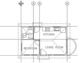
Figure 10.18: The grid circle and letter are copied to the top of all three vertical lines. - Move back to the original grid circle, and select the grip on the right side of the circle to activate it.
- Repeat steps 3 and 4 to copy the original grid circle and letter to the left end of each horizontal grid line.
- Press Esc to remove the grips. Now you’ll use the Text Edit command to change the text in each circle.
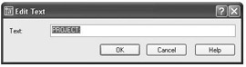
- Be sure Caps Lock is on. Type ed. Select the letter A in the second grid circle from the left on the top row to open the Edit Text dialog box.
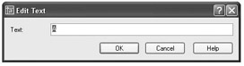
You can also start the Edit Text command by choosing Modify Object Text Edit or by double-clicking the text that you want to modify.
- With Caps Lock on, type b. The A changes to B.
- Click the A in the next circle to the right, and then type c. The A changes to C.
- Repeat this process for the remaining four grid circle letters, changing them to D, 1, 2, and 3. Press to end the Edit Text command. The letters and numbers are all in place, and the grid is complete (see Figure 10.19).
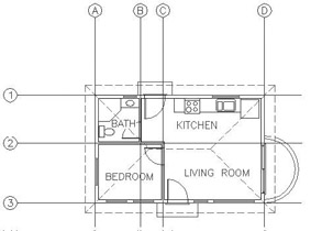
Figure 10.19: The completed grid - Zoom to Extents, and then zoom out a little to get a view of the entire drawing with the grid completed (see Figure 10.20).
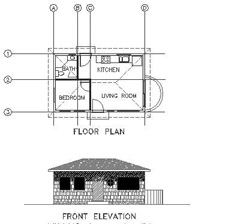
Figure 10.20: The Cabin10a drawing - Save this drawing as Cabin10a.
Often it is easier to copy existing text and modify it than to create new text, and grips are a handy way to copy text. Using the Edit Text command (technically called Ddedit) is a quick way to modify the wording of short lines of text, those that consist of a word or a few letters. The Properties palette is useful for changing all aspects of a line of text.
For the next exercise with text, you get a chance to set up some more new text styles, place text precisely, and use the Ddedit command again to modify text content. This will all be done as you develop a title block for your drawing.
Creating a Title Block and Border
The first step in creating a title block and border for the cabin drawing is deciding on a sheet size for printing the final drawing. Because many people have access to an 8.5 11-inch format printer, we will use that sheet size. If you print the drawing at a scale of ⅛" = 1'-0", will it fit on the sheet?
To answer that question, you have to ask, How big an area will fit on an 8.5 11-inch sheet at ⅛" = 1'-0" scale? The answer is really quite simple: if every inch on the sheet represents 8', you multiply each dimension of the sheet in inches by 8' per inch. For this sheet, you multiply 8.5" 8' per inch to get 68'. And you multiply 11" 8' per inch to get 88'. So the 8.5 11-inch sheet represents a rectangle with dimensions of 68' 88' at a scale of 1" = 8'-0" (usually called eighth-inch scale). That should be plenty of room for your cabin drawing. This is the information that you need to start creating the title block.
Drawing the Border
The border of the drawing will be set in from the edge of the sheet.
- Create a new layer called Tblk1. Leave the default color assigned, and make this layer current.
- Start the Rectangle command (used in Chapter 4 to make the doors).
- At the prompt, type 0,0. Then type 68',88'. A rectangle is drawn that extends off the top of the screen (see Figure 10.21a).
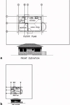
Figure 10.21: Creating the rectangle (a), and zooming out to include the entire rectangle (b) - Use Realtime Zoom to zoom out until the entire rectangle is visible in the drawing area (see Figure 10.21b). You need to fit the drawing into the rectangle as if you were fitting it on a sheet of paper—the easiest and safest way to do this is to move the rectangle over to enclose the drawing.
- At the Command: prompt, click the rectangle to turn on the grips. Grips appear at the corners of the rectangle.
- Click the lower-left grip. Press the spacebar once. Then move the rectangle over the drawing (see Figure 10.22a).
Once you activate a grip and the Stretch command begins, pressing the spacebar toggles through the other four commands in this order: Move, Rotate, Scale, Mirror.
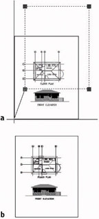
Figure 10.22: Moving the rectangle with grips (a), and the results (b) - When the rectangle is approximately in the position shown in Figure 10.22b, click. Then press Esc to turn off the grips. The rectangle is positioned around the drawing and represents the edge of the sheet.
- You need a border set in from the edge. Offset the rectangle 3' to the inside. (With a scale of 1" = 8'-0", which is another way of expressing the scale of ⅛" = 1'-0", each 1'-0" on the drawing will be represented by ⅛" on the sheet. So a 3' offset distance will create an offset of ⅛" on the printed sheet.)
- Double-click the inside rectangle to open the Properties palette.
- In the list of Geometry settings, change the Global Width from 0" to 3". Close the Properties palette, and press Esc to remove the grips.
- Zoom to Extents, and then zoom out a little to create a view in which the drawing with its border nearly fills the screen (see Figure 10.23). The outer rectangle represents the edge of the sheet of paper, while the thicker, inner rectangle is the drawing’s border.
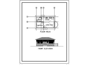
Figure 10.23: The drawing with its border
Constructing a Title Block
The title block is a box that contains general information about a drawing, such as the name of the project, the design company, and the date of the drawing. It will be set up in the lower-right corner of the border and will use the same special line—the polyline—that was used in the Rectangle command.
We first used the Rectangle command in Chapter 4 for drawing the doors. At that time, I mentioned that rectangles created with the Rectangle command are made up of a polyline whose four segments are grouped as one object. In step 10 of the previous section, you saw that these segments could have varying widths. The Polyline command, nicknamed the Pline command, allows you to draw continuous straight and curved line segments of varying widths, with all segments behaving as if they were one object.
When you explode a polyline using the Explode command, the segments lose any width they have and become independent lines. The ability of a polyline to have a width makes it useful in constructing title blocks. We’ll use the Pline command to draw the various lines that make up the title block, and then we’ll fill in the text.
- Zoom in to a view of the lower third of your drawing, including the bottom of the border. Be sure Endpoint and Perpendicular Osnaps are running.
- Click the Polyline icon on the Draw toolbar. The Specify start point: prompt appears in the Command window.
You can also start the Polyline command by typing pl or by choosing Draw Polyline.
- Click Polar on the status bar to turn on Polar Tracking. Then select the Temporary Tracking Point Osnap. Click the lower-left corner of the border, and hold the cursor directly above that point. When the vertical tracking path appears along the left boundary line, type 12'. This starts a polyline on the left side of the border 12' above the lower-left corner.
If you’re using LT, see the following “For LT Users” sidebar for a way to complete this step.
For LT Users
LT users should follow this step:
- Click Polar on the status bar to turn on Polar Tracking. Then click the Tracking button at the top of the Object Snap toolbar. Use Endpoint Osnap to click the lower-left corner of the border, hold the cursor directly above that point, and type 12'.This starts a polyline on the left side of the border 12' above the lower-left corner.
Now continue with step 4.
- Notice the bottom two lines in the Command window. The upper one tells you the current width set for polylines. The lower one displays the options for the Polyline command, with the default option being to pick a second point. This is the time to set the line width.
- Type w, and then type 3. This sets the starting and ending width of polyline segments to 3". The original Polyline command prompt returns, and you can pick a point to define the line segment (see Figure 10.24a).
- Hold the crosshair cursor on the right side of the border. When the perpendicular icon appears on the border line, click. Then press . The first polyline segment is drawn (see Figure 10.24b). The 3" width setting will stay until you change it and will be saved with the drawing file.
- Restart the Polyline command. Choose the Midpoint Osnap, and start a new segment at the midpoint of the line you just drew.
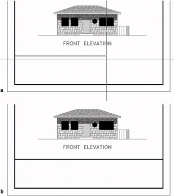
Figure 10.24: Drawing a polyline: setting the width (a), and completing the segment (b) - Move to the bottom of the border near its midpoint. When the running Perpendicular Osnap is activated, click. The left edge of the title block is drawn (see Figure 10.25a). Press to end the Polyline, or Pline, command.
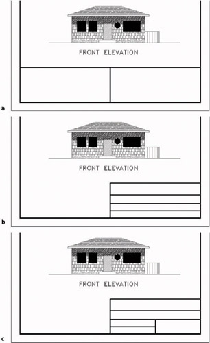
Figure 10.25: Building the title block: the left edge (a), the horizontal lines (b), and the last line trimmed (c) - Trim the left half of the first pline drawn back to the pline just drawn.
- Offset the horizontal pline down 4', offset this new line down 3', and then offset this new line down 2'-6" (see Figure 10.25b).
- Start the Pline command. Using Midpoint Osnap, start a pline at the midpoint of the third horizontal line down. Then end the segment at the bottom of the border, taking advantage of the running Perpendicular Osnap. Press to end the Pline command.
- Trim the right side of the line just above the bottom of the border, back to the line you just drew (see Figure 10.25c).
The lines for the title block are almost done. Some of the plines may look wider than others. This almost certainly is caused by the monitor distorting the picture at the current view. By zooming in, you can assure yourself that everything is correct.
- Zoom in to a close view of the title block. Notice that the intersection of the outer lines in the upper-left corner doesn’t seem clean.
- Zoom in to that corner using a zoom window (see Figure 10.26a). The lines don’t intersect in a clean corner. They need to be joined.
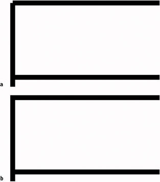
Figure 10.26: Zoomed in to the upper-left corner (a), and the corner corrected (b) - Type pe to start the Polyline Edit (Pedit) command, and select one of the two lines. You must place the pickbox on the edge of the polyline to select it, not in the middle of it.
- Type j to activate the Join option, and then select the other pline and press . The corner is corrected (see Figure 10.26b). Type x to end the Pedit command.
- Zoom Previous once. Then use Realtime Zoom to zoom out just enough to see the FRONT ELEVATION text at the top of the screen (see Figure 10.27).
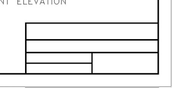
Figure 10.27: The completed lines of the title block after zooming out
Putting Text in the Title Block
The title block has five boxes that will each contain distinct pieces of information. The large one at the top will contain the name of the project. Below that will be the name of the company producing the drawing—your company. (If you don’t have a company name, make one up.) Below that on the left will be the initials of the person—you—who drew this drawing and, below that, the date. In the lower-right corner will be the sheet number, in case more than one sheet is required for this project. This follows a standard format. Most title block layouts contain this information and more, depending on the complexity of the job.
You need to put labels in some of the boxes to identify what information will be shown there. For this, you need to set up a new text style.
- Choose Format Text Style to open the Text Style dialog box. The Label text style should still be current.
- Click New, type Tblk-label, and then click OK. Leave the font set to romans.shx, but change the height to 8". Then click Apply & Close. Tblk-label is the current text style.
If you press after changing the height, the Apply button ghosts. Pressing at this point has the same effect as clicking the Apply button.
- Be sure Caps Lock is on, and then type dt to start the Dtext command. Click the Snap To None Osnap button. Then pick a point in the upper-left corner of the upper box of the title block. It doesn’t have to be the perfect location now; you can fix it after you see the text.
- Press at the rotation prompt. Type project:. PROJECT: will be placed in the upper box (see Figure 10.28a).
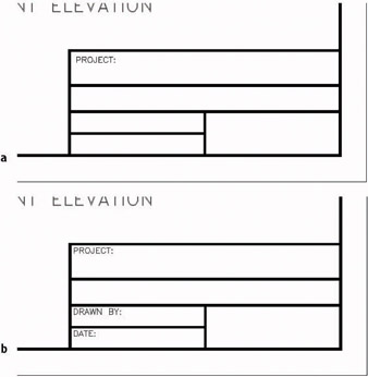
Figure 10.28: One line of text placed (a), and the text changed to the correct wording (b) - If necessary, move this text to the upper-left corner, as far as possible, while still allowing it to be readable. It will help if Polar and Osnap are temporarily turned off.
The closer you zoom in, the more precisely you will be able to fine-tune the location of the text. You then need to zoom out to check how it looks.
Tip If you have running Osnaps and need to have them off for one pick, you can click the Snap To None Osnap button. This cancels all running Osnaps for the next pick. If you need running Osnaps turned off for several picks, click the Osnap button on the status bar. Click it again when you want the running Osnaps to become active.
- Use the Copy command to copy this text to the bottom two boxes on the left, using the Multiple option and the endpoint of the horizontal lines above each of the boxes as the base and displacement points. This will keep each piece of text in the same position relative to the upper-left corner of each box.
- Type ed to start the Ddedit command. Then click the upper of the two copies of text. The Edit Text dialog box appears with PROJECT: highlighted.
- Type drawn by: and click OK. Pick the lower copy of text. The Edit Text dialog box returns.
- Type date: and click OK. Press to end the Ddedit command. The text is changed and three of the boxes have their proper label (see Figure 10.28b).
Using the Ddedit command is a quick way to change the wording of text and correct spelling. You have to change one line at a time, but the command keeps running until you stop it.
The next area to work on is the lower-right box. This is where the sheet number is located, and it is usually displayed in such a way that the person reading the drawing can tell not only the page number of the current sheet, but also the number of sheets being used for the project. We will create a new text style for this box.
- Start the Style command. In the Text Style dialog box, click New.
- Type Sheet_No and click OK. For the font, select romand.shx. Change the height to 1'-3". Click Apply, and then click Close. Sheet_No is now the current text style.
- You will need to center the text horizontally in the box. This will require breaking the horizontal line running across the top of this box at the upper-left corner of the box. To do this, click the Break At Point button on the Modify toolbar. Then select the line to break at a point where no other lines are touching it.
- Use the Endpoint running Osnap to pick the upper-left corner of the box. AutoCAD breaks the line at that point without leaving a gap and ends the command.
- Start the Dtext command and type j. Then type tc. Select Midpoint Osnap, and pick a point on the line across the top of the box.
- Press at the rotation prompt. With Caps Lock on, type sheet no. : 1 of 1. (When you get to the of, turn off Caps Lock.) For clarity, leave an extra space after the first 1 and before the second 1. The text is inserted into the box and is centered horizontally (see Figure 10.29a).
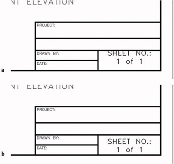
Figure 10.29: The text after being inserted (a), and after centering vertically (b) - With Polar Tracking on, use the Move command to move the text down and center it vertically in the box (see Figure 10.29b). Remember, when you select the text to move it, you have to pick each line because they are two separate objects.
Now it’s time for you to experiment. Use the techniques you just went through to fill in the text for the other four boxes. Feel free to try other fonts, but you will have to adjust the height for each text style so that the text fits in its box. Some guidelines for height follow.
|
Box |
Recommended Height of Text |
|---|---|
|
Project: |
2'-6" |
|
Company: |
1'-3" |
|
Drawn By: |
1'-0" |
|
Date: |
1'-0" |
You will have to set up a new style for each new font or height you choose unless you set up a style with a height of 0'-0". In that case, you will be prompted for the height each time you start to place text in the drawing. This is the recommended way to operate for the top two boxes because it will give consistency to the text even when heights vary. You might try several fonts and then come back to this technique at the end. I also recommend that you use a relatively simple font for the text in the Drawn By and Date boxes, something a little larger and possibly bolder than the labels in those boxes.
Try these fonts:
- romant.shx or romanc.shx
- Any of the swis721 series
- Times New Roman
- Technic
- SansSerif
- CityBlueprint or CountryBlueprint
- Arial
In the top two boxes, you can center the text vertically and horizontally if you draw a line diagonally across the box, choose Middle as a justification for the text, and use Midpoint Osnap to snap to the diagonal line when you start the text. For the Drawn By and Date boxes, centering the text horizontally is not advisable because the label text already in the boxes takes up too much space. However, you can use the diagonal line to center it and then move the text to the right until it makes a good fit. Using Polar Tracking will keep the new text vertically centered.
Be careful in your use of running Osnaps as you position text. If you are eyeballing the final location, it is best to have no running Osnaps. On the other hand, if you are precisely locating justification points by snapping to lines and other objects, you might try having the following Osnaps running: Endpoint, Intersection, Perpendicular, and Insertion, with Midpoint optional.
When you finish, your title block should look something like Figure 10.30. In this sample, romant.shx font was used for a style that was set to zero height and then applied to the top two boxes at the recommended heights. The romand.shx font was used for the Drawn By and Date boxes, also at the recommended height.
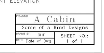
Figure 10.30: The completed title block
If you are going to design your own company title block, be ready to spend a little time setting it up and deciding which fonts will give the look that best reflects the image you want to project. You can then use this title block on all your subsequent projects.
Zoom to Extents, and then zoom out a little to view the entire drawing. Save this drawing as Cabin10b (see Figure 10.31).
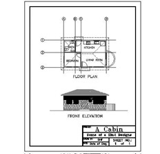
Figure 10.31: The latest version of the cabin drawing
A Look at AutoCAD’s Title Blocks
Now that you’ve created a title block and a border, let’s take a brief look at the title blocks and borders that AutoCAD provides in its template files and see how you can use these files to set up a new drawing. To follow the steps, set up AutoCAD so that it does not display a Start Up dialog box when you create a new drawing. Choose Tools Options to open the Options dialog box. Make the System tab active. In the General Options area, be sure the Start Up drop-down list has Do Not Show A Start Up Dialog displayed. If it doesn’t, open the list and select that option. Click Apply and then click OK.
- Click the QNew icon on the Standard toolbar to open the Select Template dialog box.
- Double-click ANSI A (portrait) - Color Dependent Plot Styles. The new drawing appears with a title block and border (see Figure 10.32). In addition, this sheet has extra lines, arrows, and a section near the upper edge for listing revisions to the drawing.
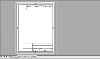
Figure 10.32: A new drawing made from the ANSI A (portrait) template - Zoom in to the title block on the lower part of the drawing. Notice that it has spaces for the scale and sheet number, among other information, and that some areas are left blank.
- Close this drawing, and click the QNew button again to look at some of the other template files on the list. Don’t worry about the part of the template name that identifies plot style types. That will be covered in Chapter 14. The background for the template files is gray because they use layouts, which are introduced in Chapter 13.
When you open a new drawing by selecting a template file, AutoCAD uses the template file as the basis of your new drawing. It copies the information in the template file onto the new drawing file and names the new drawing Drawing 1, Drawing 2, and so on. You can convert any drawing into a template file. Simply choose File Save As, and in the Files Of Type drop-down list at the bottom of the Save Drawing As dialog box, select AutoCAD Drawing Template (*.dwt). The new file will have the .dwt extension. It can be stored in AutoCAD’s Template folder or any folder you choose. When you click Save, the Template Description dialog box opens, giving you the option of writing a description of the new template file and choosing whether the template will use metric or English units (see Figure 10.33).
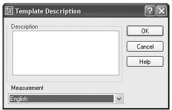
Figure 10.33: The Template Description dialog box
The final part of this chapter introduces you to multiline text, which you will also work with as you learn about dimensions in the next chapter, and tables.
Using Multiline Text
Multiline text (often referred to as Mtext) is a more complex form of text than single-line text. It can be used the same way single-line text has been used in this chapter, and it can do more. If you have several lines of text, or if you need certain words within a line of text to appear differently than the adjacent words, multiline text is the best thing to use.
A paragraph of multiline text is a single entity. The text wraps around, and you can easily modify the length of a line after you place the text in the drawing. Within the multiline text entity, all text can be edited and behaves as if it were in a word processor. You can give a special word or letter of the text its own text style or color. Everything you learned about defining a new text style applies to multiline text, because both kinds of text use the same text styles. Just as polylines become lines when exploded, multiline text is reduced to single-line text when exploded.
Use the Explode command to turn multi-line text into single-line text, to unblock objects in a block reference, and to convert a polyline into regular lines. Click the Explode button on the Modify toolbar to start the command.
Dimensions use multiline text, and any text that is imported into an AutoCAD drawing from a word-processing document or text editor will become multiline text in the drawing. In this section, you will learn how to place a paragraph of multiline text in the cabin drawing and then modify it. In Chapter 11, you will work with dimension text and text with leader lines, both of which use multiline text.
We will start by adding a note in the lower-left corner of the drawing, using the Multiline Text command.
- Click the Make Object’s Layer Current button just to the right of the drop-down Layer Control list on the Layers toolbar. Then click the FRONT ELEVATION text to make the Text1 layer current. Zoom in to the blank area to the left of the title block in the lower-left corner of the cabin drawing.
- Click the Osnap button on the status bar to the off position. This will temporarily disable any running Osnaps. Then click the Multiline Text button on the Draw toolbar. The Command window displays the name of the current text style and height and prompts you to specify a first corner.
You can also start the Multiline Text command by typing t or by choosing Draw Text Multiline Text.
- Select a point near the left borderline in line with the top of the title block. The prompt now reads Specify opposite corner or [Height/Justify/Line spacing/Rotation/Style/Width]:. These are all the options for the Multiline Text command.
- If the current style is Label, go on to step 5. Otherwise type s for the Style option and type label.
- Drag open a window that fills the space between the left border and the left side of the title block. This defines the line length for the multiline text (see Figure 10.34). Click to finish the window.
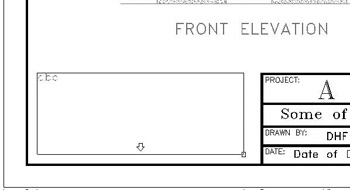
Figure 10.34: Making a Multiline Text window - The Text Formatting toolbar appears, and below it, the Multiline Text Editor opens where you made the window in step 5. This is where you will type the text. In the drop-down lists on the toolbar above, you can see the current text style and its font and height.
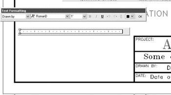
- Open the drop-down list on the left and select Label. Type the following text, using single spacing and pressing Enter only at the end of the first line and at the end of each note.
GENERAL NOTES:
- All work shall be in accordance with the 2000 Ed. Uniform Building Code and all local ordinances.
- Roof can be built to be steeper for climates with heavy snowfall.
- Solar panels available for installation on roof.
- All windows to be double-paned.
When finished, click OK. The text is placed in the drawing (see Figure 10.35a). The window you specified was used only to define the line length. Its height does not control how far down the text will come; that is determined by how much text you enter.
You can expand the Multiline Text Editor typing area to the right and down to accommodate more lines of text and greater line length.
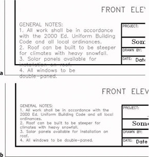
Figure 10.35: Mtext in the drawing (a), and modified to be smaller (b) - Double-click anywhere on the new text to display the Multiline Text Editor and the Text Formatting toolbar.
- Move the cursor to the upper-left corner of the window containing the text and in front of the G in the first word. Hold down the left mouse button and drag to the right and down until all the text is highlighted. Release the mouse button.
In the rightmost drop-down list on the Text Formatting toolbar, change the Text Height from 1' to 9" and click OK. The text is redrawn smaller and now makes a better fit within the space available (see Figure 10.35b).
- Double-click the Mtext again. The Multiline Text Editor opens and displays the text you just clicked.
- Highlight all the text again. In the middle drop-down list on the Text Formatting toolbar, select SansSerif as the current font. The selected text changes to the new font.
- Click OK. The Mtext in the drawing has become more compact, and there is room for more notes (see Figure 10.36).
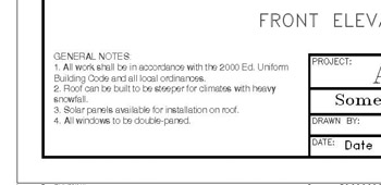
Figure 10.36: The results of a font modification
SansSerif is a TrueType font supported by Windows. When used in AutoCAD drawings, it can be italic or boldface. To see how to change individual words within the text, we will underline and boldface the Uniform Building Code text.
- Double-click the Mtext again to open the Multiline Text Editor dialog box.
- Use the same technique as earlier to highlight just the Uniform Building Code text. Then click the Bold (B) and Underline (U) buttons on the Text Formatting toolbar. The selected text is underlined and boldfaced.
- Click OK. The text is redrawn with the changes (see Figure 10.37).
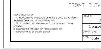
Figure 10.37: The Mtext with individual words modified
You can also italicize individual words and give them a different color or height from the rest of the Mtext by using the other tools on the Text Formatting toolbar. I encourage you to experiment with all these tools to become familiar with them.
You can easily alter the length of a line to make the Mtext fit more conveniently on the drawing. Let’s say you’ve decided to put your company logo to the left of the title block. You need to squeeze the text into a narrower space. You have some extra room at the bottom, so you should be able to do it.
- At the Command: prompt, click the Mtext to select it. Four grips appear at the corners of the body of Mtext.
- On the status bar, be sure Polar is on and Osnap is off. (For AutoCAD users only, Otrack should also be off.) Then click the upper-right grip to activate it.
- Slowly move the cursor to the left. When the bottom line of text gets close to the bottom line of the border, you will have moved about a third of the way to the left borderline (see Figure 10.38a).
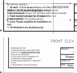
Figure 10.38: Modifying the Mtext line length with grips (a), and the results (b) - Click the mouse, and then press Esc. The text is squeezed into a narrower space but still fits on the page (see Figure 10.38b).
The ruler at the top of the Mtext Editor window has two sliding indicators for setting indentions. The top indicator is for the first line, in case it is a title. The bottom indicator is for the rest of the text. We set that one in a little to make the note numbers stand out.
- Double-click the text one last time.
- In the Mtext Editor window, highlight the four notes.
- Use the mouse to slide the bottom indicator on the ruler two notches to the right (see Figure 10.39a).
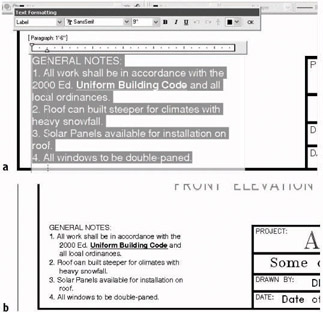
Figure 10.39: Adjusting the paragraph slider on the ruler (a), and the results (b) - Click OK. The list of notes is now more readable (see Figure 10.39b).
- Zoom to Extents, and then zoom out a little to a view of the whole drawing (see Figure 10.40). You won’t be able to read the Mtext at this magnification, but it will look fine when you print your drawing.
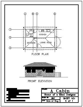
Figure 10.40: The full drawing - Save this drawing as Cabin10c.
Other Aspects of Multiline Text
There are several other features of multiline text that I can only touch on in this book. I encourage you to experiment with any features that you might find useful to your work.
Adjusting the Mtext Editor Size
If you zoom in too close to see all of one body of Mtext on your screen, the Mtext Editor will make the text smaller so it can be viewed. Conversely, if you zoom out so much that the text can’t be read, as in Figure 10.40 (shown previously), the Mtext Editor will scale up the text to a readable size (see Figure 10.41).
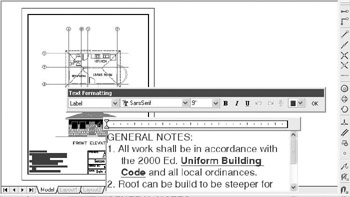
Figure 10.41: The Mtext Editor with the text enlarged to a readable size
Justification Points
Mtext has justification points similar to those of single-line text, and they behave the same way. The default justification point for Mtext, however, is the upper-left corner of the body of text, and the available options are for nine points distributed around the perimeter of the body of text and at the center (see Figure 10.42).
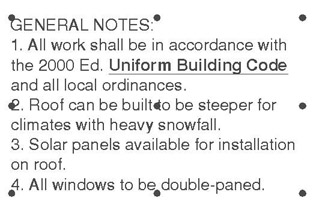
Figure 10.42: Justification points for Mtext
When you need to modify the justification of Mtext, open the Mtext Editor, place the cursor in the Editing window, and right-click to display a shortcut menu that contains several commands for modifying Mtext, including Justification. I’ll describe the other items on this menu in the upcoming “Tools for Modifying Multiline Text” sidebar.
Special Characters
With Mtext, you can add special characters—the degree symbol, the diameter symbol, and so on—that are not included in most font character packages. You will have a chance to do this in the next chapter.
If you want to play around with the Mtext in the cabin drawing, make a copy of it and place it outside the drawing. Double-click it and see what you can learn about the Multiline Text Editor, the Text Formatting toolbar, and the Mtext shortcut menu. Features of the last two are summarized in the following sidebar.
Tools for Modifying Multiline Text
Here’s a brief summary of the various features of the Text Formatting toolbar and the Mtext shortcut menu:
The Text Formatting Toolbar
The features of the Text Formatting toolbar are:
Style Drop-Down ListContains a list of all existing text styles in the drawing file.
Font Drop-Down ListSets the font for the selected text or sets the font for subsequently entered text.
Height Drop-Down Text BoxSets the height for selected text or sets the height for subsequently entered text.
Bold, Italic, and Underline ButtonsChanges selected text or sets up for subsequently entered text.
Undo ButtonUndoes the last editing action.
Redo ButtonRedoes the last undo.
Fraction ButtonConverts selected text into any of three styles of stacked fractions. Use one of three symbols to specify the fraction bar: horizontal (/), slanted (#), and none (^).
Text Color Drop-Down ListChanges the color of a selected portion of text or sets a color for subsequently entered text.
OK ButtonExecutes what has been done in the Mtext Editor and returns you to your drawing.
The Mtext Shortcut Menu
The features of the Mtext shortcut menu are:
Undo, Redo, Cut, Copy, and PasteThese commands are self-explanatory and appear on most AutoCAD shortcut menus.
Insert FieldOpens the Field dialog box, which you use to insert a field into the selected text. If you select text containing a field, this menu item changes to three menu items: Edit Field, Update Field, and Convert Field To Text.
Indents And TabsOpens the Indents And Tabs dialog box. It has settings for indenting the first line and subsequent paragraphs of Mtext (similar to what the sliders do on the ruler above the Mtext Editor window) and tab stop positions.
JustificationOpens a flyout menu that contains the nine justification points for Mtext, illustrated earlier in Figure 10.42. Use this to change the justification of selected text or to set up justification for new text.
Find And ReplaceOpens the Replace dialog box, in which you search for a word or a series of words (text string) and replace them with text that you specify.
Select AllHighlights all the selected text.
Change CaseChanges the case of all highlighted text to uppercase or lowercase.
AutoCAPSWhen checked, capitalizes all text.
Remove FormattingRemoves formatting, such as bold, underline, and so on, from highlighted text.
Combine ParagraphsJoins highlighted individual paragraphs into one paragraph.
SymbolImports symbols (such as diameter, degree, and so on) that are not available in the font you are using.
Import TextUsed to import a word-processing or text file into an AutoCAD drawing. The maximum size allowed is 16KB, so the smallest Word document possible is too large; you can, however, use files in Text Only or RTF formats. Clicking the Import Text button opens the Select File dialog box that displays only files having the .txt and .rtf extensions. You can bring in text files with other extensions if you enter the full filename with its extension and if they are not larger than 16KB. Text comes in as Mtext and uses the current text style, height setting, and layer. The imported file may not retain complex code fields for such things as tabs, multiple margin indents, and so on.
Background MaskOpens the Background Mask dialog box in which you specify color for and activate a background mask to go behind the selected Mtext object.
HelpOpens a help page on Multiline text.
Character SetOpens a menu of several languages. When applicable, the codes of the selected language will be applied to selected text.
Creating a Table
All professions that use AutoCAD use tables to consolidate and display data in organized formats. Architectural construction documents usually include at least three basic tables: door, window, and room finish schedules. These are usually drawn in table form and display the various construction and material specifications for each door or window type or for each room. To illustrate the tools AutoCAD offers for creating tables, we’ll construct a simple door schedule for the cabin.
You create tables in AutoCAD by first creating a table style and then creating a table using that style—it’s a process similar to that of defining a text style and then inserting text in a drawing using that style.
Defining a Table Style
Table styles are more complex than text styles. They include parameters for width and height of rows and columns and, among other things, at least one text style.
- Make Cabin10c the current drawing. We’ll make a new file by saving this file to the new file’s name.
- Choose File Save As, and in the Save Drawing As dialog box, rename this file as Cabin10c-Sheet2 and click Save.
- Make sure all layers are thawed and turned on, and then erase everything in the drawing except the border and the title block. This drawing still has all the layers, blocks, and text styles that the Cabin10c drawing had.
- In the title block, change the sheet number from “1 of 1” to “2 of 2.”
- Create a new layer called Tables, assign it color number 7, and make it the current layer. Choose Format Table Style to open the Table Style dialog box (see Figure 10.43). On the left is the Styles list box. It displays all defined table styles. To the right of that is a preview window that displays the current table style—in this case, the Standard style because it’s the only one defined so far. Below the Styles list box is a drop-down list called List that gives you options for which table styles to display. To the right of the Preview Of window are four buttons.
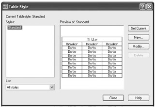
Figure 10.43: The Table Style dialog box - Click the New button to open the Create New Table Style dialog box (see Figure 10.44). In the New Style Name text box, Copy of Standard is highlighted.
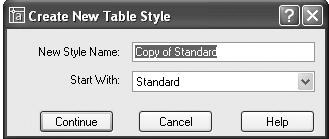
Figure 10.44: The Create New Table Style dialog box - Type Door Schedule to create a new table style name and click Continue. The New Table Style dialog box opens with Door Schedule in the title bar (see Figure 10.45). The new style we are defining will be like the Standard style with the changes we make here. Notice the three tabs at the top: Data, Column Heads, and Title. They refer to the three parts of the sample table that’s displayed in the preview window to the right. You can specify text and line characteristics for each of the three parts. Be sure the Data tab is active and on top.
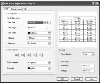
Figure 10.45: The New Table Style dialog box - Click the Browse button to the right of the Text Style drop-down list to open the Text Style dialog box. We want a new text style for the door schedule.
- Define a new style called Table, and use the Arial font and 0 height. Click Apply and then click Close. Then open the Text Style drop-down list and select the new text style you created, Table.
- Set the Text Height to 9". Leave Text Color and Fill Color at their default settings. Change Alignment to Middle Center.
- Click the Column Heads tab in the New Table Style dialog box and make it active. Choose the same text style (Table) and set the height to 12".
- Click the Title tab in the New Table Style dialog box, select the Table text style again, and set the height to 15".
We’ll leave the Border properties at their default settings. These control the visibility of the horizontal and vertical lines of the table, their lineweight, and color. Your individual professions may have their own standards for these parameters.
- Leave Table Direction set to Down. In the Cell Margins area, change the Horizontal and Vertical settings to 6". Click OK.
- Back in the Table Style dialog box, in the Styles list, click Door Schedule to highlight it, and then click the Set Current button to make it the current table style (see Figure 10.46). Then click Close.
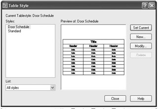
Figure 10.46: The Table Style dialog box with Door Schedule as the current table style
Now let’s look at the geometry of the new table.
Designing a Table
The height of the rows has been set by the parameters in the Door Schedule table style. We now need to determine the width of the columns and figure out how many columns and rows we need for the door schedule. This is done as we insert a new table. Remember that Door Schedule is the current table style.
- Zoom in to the upper portion of the drawing. Near the bottom of the Draw toolbar, click the Table icon to open the Insert Table dialog box (see Figure 10.47). In the Table Style Settings area, the Door Schedule is displayed in the Table Style Name drop-down list because it is now the current table style. An abstract version of the table is displayed below in the preview window.
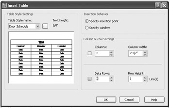
Figure 10.47: The Insert Table dialog box - On the right side, click the Specify Window radio button. We’ll make a window to define the table. It will be the full horizontal width of the drawing inside the borders. Below, in the Column & Row Settings area, Column Width and Data Rows ghost out because they are defined by the window that we specify to define the table in the drawing. We need to define only the number of columns. We won’t worry about the row height for now. It’s determined by the number of lines of text, and we’re using only one line of text.
- We will have five categories to describe the doors, so set the Columns box to 5. Each column is initially set to the same width. We can adjust it later. Click OK.
- Back in the drawing, turn off Osnap and Polar on the status bar. Then click a point near the upper-left corner of the border, just inside it. This establishes the upper-left corner of the new table.
- Drag the cursor across the drawing and down until the screen displays a table that spans the drawing and has a title bar and six rows below (see Figure 10.48a). When that is displayed, release the mouse button. The new table is displayed inside the drawing’s border (see Figure 10.48b). Its title bar has a flashing cursor, and above the drawing, the Text Formatting toolbar floats.
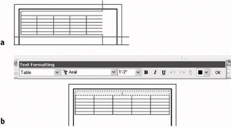
Figure 10.48: Dragging the new table across the drawing (a) and the results (b) - With Caps Lock on, type door schedule. The cursor jumps to the upper-left cell on the table. This is the row for the column heads.
- With Caps Lock on, type sym. and press the Tab key. Then, moving across the header row, type (in caps) name, press the Tab key, type width & height, press the Tab key, type type, press the Tab key, and then type material. This completes the row of column heads (see Figure 10.49a).
- Now you can fill in the data for the door schedule that’s shown in Figure 10.49b in the same manner. Pressing the Tab key instead of moves the activated cell left to right across each row and then down to the next row. Pressing moves the activated cell down each column and then ends the command. Double-click in a cell to activate that cell and display the Text Formatting toolbar again.
- When finished, click OK on the Text Formatting toolbar (see Figure 10.49b). Some of the cells have increased in size vertically to accommodate the long text. You can adjust the width of some columns to make more room in others.
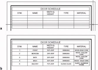
Figure 10.49: The table with its title and column heads (a), and the table completely filled in (b) - Click any line in the table. Grips appear, and the lines and text in the table ghost (see Figure 10.50a).
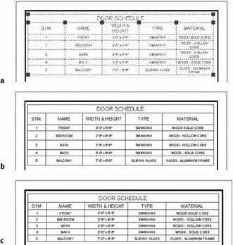
Figure 10.50: The table after being selected (a), the table with column width adjusted (b), and the table after final adjustment (c) - Click the grip at the top right of the SYM. column, and then drag it to the left to narrow that column. Click the other grips at the top of the columns to drag them and narrow or widen them. The This should give you a result similar to Figure 10.50b. The boxes of data are not all the same size vertically.
- Click on the table again to bring back the grips. Click the grip in the lower-right corner. Turn off Running Osnaps but keep Polar on, then move the cursor straight up above the selected grip until the cells appear to have the same vertical height. Click and then press Esc to remove the grips (see Figure 10.50c).
- Save this drawing. It’s already been named Cabin10c_Sheet2.
This concludes the chapter on text. In the next chapter, we look at the dimensioning features of AutoCAD. You create and manage dimensions using techniques similar to the ones you learned to work with text and tables.
If You Would Like More Practice
Trades and other professions outside the area of architecture and construction will use text with AutoCAD and AutoCAD LT in exactly the same way as demonstrated in this chapter.
For more practice using single-line text, follow these steps:
- Close all drawings, and then open Cabin04c-addon.dwg.
- Using DesignCenter, bring in the Title and Label text styles from the Cabin10a drawing while it is closed.
- Add labels to the features that were added.
- Use the Title text style to identify the addition as GARAGE.
- Use the Label text style to give the features the following names: WALKWAY, STORAGE, OFFICE, and CAR.
For more practice using Mtext, follow these steps:
- Open Cabin10c, and zoom in to the blank space between the structural grid and the top border.
- Create a new text style called Description that uses the Times New Roman font and a height of 12".
- Start Mtext, and specify a rectangle for the text that covers the width of the sheet between the borders and occupies the space above the structural grid.
- Enter the following text exactly as shown here, spelling errors and all:
This is a design for a small vaction cabin. It contains approximately 380 square feet of living space and includes one bedrooms and one bath. It can be adopted to provide shelter in all climates and can be modified to allow constuction that uses local building materials. Please sund all inquiries to the manufacturer.
- Double-click the new text and make these changes:
- Correct all spelling errors.
- Change “square feet” to “sq. ft.”
- Boldface the following : “one bedroom,” “one bath,” “all climates,” and “local building materials.”
- Italicize the last sentence.
- See if you can modify the shape of the defining rectangle so that the text fits in the space in the upper-left corner.
Are You Experienced?
Now you can
- set up text styles
- place single-line text in a drawing for titles and room labels
- create a grid for a drawing
- modify single-line text
- construct a title block and place text in it
- use AutoCAD template files
- place Mtext in a drawing
- modify Mtext in several ways
- set up a table style and create a table
Introduction
- Getting to Know AutoCAD
- Basic Commands to Get Started
- Setting Up a Drawing
- Gaining Drawing Strategies: Part 1
- Gaining Drawing Strategies: Part 2
- Using Layers to Organize Your Drawing
- Grouping Objects into Blocks
- Generating Elevations
- Working with Hatches and Fills
- Controlling Text in a Drawing
- Dimensioning a Drawing
- Managing External References
- Using Layouts to Set Up a Print
- Printing an AutoCAD Drawing
- Appendix A Look at Drawing in 3D
EAN: N/A
Pages: 159
