Appendix A Look at Drawing in 3D
Appendix A Look atDrawing in 3D
|
|
Nothing in CAD is quite so fascinating as drawing in 3D. Compared with a traditional 3D rendering of a building on a drafting board that uses vanishing points and projection planes, a true 3D computerized model of a building that can be rotated and viewed from any angle, as well as from the inside, is a world of difference. Many architectural firms still use the drafting board to create 3D presentation drawings, even though they use AutoCAD for their construction drawings. But more and more of them are using AutoCAD’s 3D features to create either perspective drawings or simple 3D models that are then traced over by hand in the process of creating the final presentation drawing. So it’s useful to acquire some skills in working in 3D. It’s also a lot of fun. |

Because AutoCAD LT does not have any capacity to draw in three dimensions, this entire appendix does not apply to users of that program.
Constructing a 3D model of a building requires many of the tools that you have been using throughout this book and some new ones that you will be introduced to in this appendix. Your competence in using the basic drawing, editing, and display commands is critical to your successful study of 3D for two reasons. First, drawing in 3D is more complex and difficult than drawing in 2D, and it can be frustrating. If you aren’t familiar with the basic commands, you will become that much more frustrated. Second, accuracy is critical in 3D drawing. The effect of errors is compounded, so you must be in the habit of using tools, such as the Osnap modes, to maximize your precision.
Don’t be discouraged; just be warned. Drawing in 3D is a fascinating and enjoyable process, and the results you get can be astounding. I sincerely encourage you to make the effort to learn some of the basic 3D skills presented here.
Many 3D software packages are on the market today, and some are better for drawing buildings than others. Many times, because of the precision that AutoCAD provides, a 3D .dwg file will be exported to one of these specialized 3D packages for further work, after being laid out in AutoCAD. Other drawings will be created in 2D, converted to 3D, and then refined into a shaded, colored, and textured rendering with specific lights and shadows. In this appendix, we will look at the basic techniques of solid modeling and touch on a couple of tools used in surface modeling. In the process, you will learn some techniques for viewing a 3D model. At the end of the appendix, we will introduce the processes of setting up and rendering a 3D model.
D Modeling
We will begin by building a 3D model of the cabin, using several techniques for creating 3D solids and surfaces. When using solid modeling tools, the objects you create are solid, like lumps of clay. They can be added together or subtracted from one another to form more complex shapes. By contrast, 3D surfaces are a composite of two-dimensional planes that stretch over a frame of lines the way a tent surface stretches over the frame inside.
As you construct these 3D objects, you will get more familiar with the User Coordinate System, learn how it is used with 3D, and begin using the basic methods of viewing a 3D model.
Viewing a Drawing in 3D
Let’s start with Cabin07b. This version of the cabin has all the basic components of the floor plan on their respective layers, with no hatch patterns and no front elevation or title block. If you haven’t been following through the whole book and saving your work progressively, you can download this file from Sybex’s website, www.sybex.com. You can still follow along if you have another floor plan to use for the exercise that isn’t too much more complex than that of the cabin.
- Open Cabin07b. When the floor plan displays, make the Walls layer current and turn off all other layers. Your drawing will look like Figure A.1. Try to start thinking of it in three dimensions. The entire drawing is on a flat plane parallel to the monitor screen. When you add elements in the third dimension, they will project straight out of the screen toward you if they have a positive dimension, and straight through the screen if they have a negative dimension. The line of direction is perpendicular to the plane of the screen and is called the z-axis. You are familiar with the x- and y-axes, which run left and right and up and down, respectively. Think of the z-axis for a moment as running in and out of the screen.
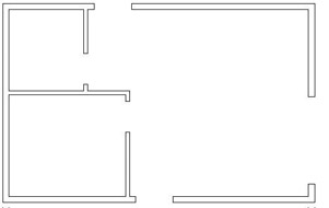
Figure A.1: Cabin07b with all layers turned off except Walls - If the User Coordinate System icon is not visible on your screen, choose View Display UCS Icon On to place a check mark next to On. The UCS icon appears again. We turned it off in Chapter 5 and then used it in Chapter 8, to help construct some of the elevations, and we’ll be using it again in a moment. For now, just keep an eye on it as the drawing changes. Remember that the icon’s arrows indicate the positive direction for the x-, y-, and—in 3D—z-axes.
- Now you’ll change the view from a plan view of the drawing—looking straight down at it—to one in which you are looking down at it from an angle. Choose View 3D Views SW Isometric. (SW means from the southwest.) The view changes to look like Figure A.2. Notice how the UCS icon has changed with the change of view. The X and Y arrows still run parallel to the left side and bottom of the cabin, but the icon and the floor plan are now at an angle to the screen. And the z-axis is visible.
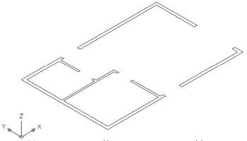
Figure A.2: The walls as seen from the SW Isometric view - Zoom out and pan down to give yourself some room to put the walls in 3D.
Making the Walls
The main task ahead is to create what is called a 3D model of the cabin. We will be using solid elements for the cabin’s walls, doors, windows, floor, and steps. You will learn several ways of viewing your work as you progress. To make the walls, we’ll start with a solid box and then, like a sculptor, remove from the box everything that is not an interior or exterior wall. The elements to be removed will be the spaces of the rooms and the openings for the doors and windows.
- Set the Endpoint Osnap to be running, and be sure Polar and Ortho are turned off. Create a new layer called 3D-Walls, assign it color 22, and make it current.
- Choose Draw Solids Box. Click the lowest corner of the walls, and then click the uppermost corner. At the Specify height: prompt, type 9'. A box is drawn over the entire floor plan, and AutoCAD displays it as a wireframe (see Figure A.3a). Wireframes are 3D drawings in which the lines represent the intersection of walls or other planes. What you are viewing is actually a solid block, a fact that will become apparent as we move along.
For the various heights of the windows, doors, roof, and so on, see Figure 8.1 in Chapter 8.
- Restart the Box command and repeat step 2 to make another 9'-high box in the living room. Pick the inside corner to the left of the front door and the inside corner where the refrigerator stands (see Figure A.3b).
- Repeat step 2 again and create a third box in the remaining part of the living room that wasn’t included in the second box (see Figure A.3c).
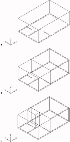
Figure A.3: The first box covers the floor plan (a), a box fills most of the living room (b), and a third box fills the rest of the living room (c). - Repeat step 2 twice more to create 9' boxes at the interior corners of the bedroom and bathroom (see Figure A.4).
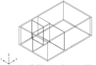
Figure A.4: The interior spaces of the cabin are filled with boxes.
Notice that the empty spaces between the boxes’ vertical faces are the exterior and interior walls. Because all five boxes are solid, we can subtract the four inside boxes from the larger outside box and be left with the walls.
- Choose Modify Solids Editing Subtract. Pick the large outside box, and then press . Pick the four smaller inside boxes and press . The smaller volumes are subtracted from the larger volume, creating your walls (see Figure A.5a).
When I instruct you to “pick” an object when working in 3D, you need to click on an edge of the object, or on a line that helps define the object.
- You need a better view to really see what has happened. Choose View Hide. Hidden lines are removed, and you can see solid walls (see Figure A.5b). The walls are one object, consisting of the large box after the smaller boxes were subtracted from it.
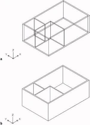
Figure A.5: The solid after subtracting the interior boxes (a) and the view after using the Hide command (b) - Choose View Regen to restore the hidden lines. We’ll use a similar procedure to put in the doorway openings.
When you choose View Regen, AutoCAD recalculates all the geometry of the drawing as if you were just opening it. This process is called a regeneration. Choosing View Redraw merely refreshes the screen.
Cutting Doorway Openings
The five doorway openings vary in width but have the same height. We can make boxes where the openings should be and then subtract them from the wall solid object.
- Create a new layer called 3D-Doors and make it current. Assign White as this layer’s color.
- Freeze the 3D-Walls layer. Make a zoom window that includes just the five openings in the floor plan of the walls. Be sure Endpoint Osnap is running.
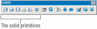
- Display the Solids toolbar and dock it on the right side of the drawing area, next to the Object Snap toolbar. Click the Box icon to start the Box command.
You can also start the Box command by choosing Draw Solids Box or by typing box.
- Make a box for the front, bedroom, and balcony door openings. Click opposite corners of each opening, and then enter 7'6 at the Specify height: prompt. Copy the front door box to the back door opening, and copy the bedroom box to the bath opening.
- Zoom Previous (see Figure A.6a).
- Thaw the 3D-Walls layer.
- Choose Modify Solids Editing Subtract. Click the wall solid, and then press .
- Click the five boxes that are serving as openings, and press (see Figure A.6b).
- Choose View Hide (see Figure A.6c). The doorway openings have been cut.
- Choose View Regen. The window openings can be made in the same way, after a modification to the floor plan.
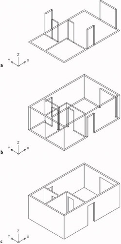
Figure A.6: The boxes in all five openings (a), the wall solid after subtracting the boxes (b), and the view after a Hide
Subtracting Window Openings
As you might expect, the window openings will be cut out of the walls just as the doorway openings were. The only difference is that the bottoms of the window openings sit above the 2D floor plan.
- Create a new layer called 3D-Windows and make it current. Let it take on the default color. Before you leave the Layer Properties Manager dialog box, turn off the Walls layer, turn on the Windows layer, and freeze the 3D-Walls layer. Only window blocks should be visible (see Figure A.7). If the screen doesn’t display what is illustrated in the book or what you expect, choose View Regen.
When you want to make 2D layers invisible, it doesn’t matter whether you freeze them or turn them off. But when working with 3D layers, it is best to freeze them. When they are frozen, they won’t interfere with the appearance of a 3D model during a Hide.
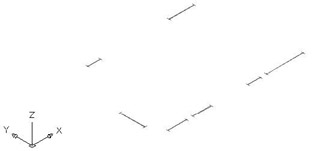
Figure A.7: The cabin drawing in 3D with only the Windows layer visible - Zoom in to a closer view as you did for the doorway openings.
- Use the Box command to create six box solids that are 3'-6" high at each of the windows except the 2'-wide window in the front wall of the living room, then Zoom Previous (see Figure A.8a). The 2' window in the living room is round and will be dealt with separately.
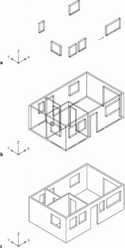
Figure A.8: The window solid boxes that were created on the floor plan (a), the wall solid and the window boxes after being raised (b), and the view after a Hide (c) - Start the Move command. Select the six boxes, and then press . Click any point on the screen, and then type @0,0,4'. The window boxes are moved up 4'.
- Thaw the 3D-Walls layer and zoom out if necessary. The drawing should look like Figure A.8b.
- Choose Modify Solids Editing Subtract. Click the wall solid, and then press .
- Pick the six window boxes, and then press . The window openings are cut out of the walls. After hiding, the drawing looks like Figure A.8c.
Now we need to create a circular window opening for the front wall. We’ll use a second basic solid shape, or primitive, to cut this circular hole. AutoCAD has six primitive shapes that are solids. When you choose Draw Solids, the top of the cascading menu displays them.
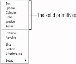
On the Solids toolbar, the primitives have icons that illustrate their basic shapes.
So far, we’ve used only the box. For the circular window, we’ll use the cylinder.
- Zoom in close to a view of the front wall, as shown in Figure A.9a. We will need to change the UCS icon to make the cylinder.
After a hide, zooming or panning automatically changes the view back to the wireframe.
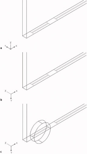
Figure A.9: A close view of the 2' window (a), the UCS after reorientation (b), and the cylinder placed in the wall (c) - Type ucs x –90. The UCS icon rotates such that the plane defined by the x- and y-axes is parallel to the front wall and the z-axis points away from you (and is therefore dashed) (see Figure A9.b).
- Click the Cylinder icon on the Solids toolbar. Then follow the prompts in the Command window.
- Use Insertion Osnap to locate the center point for the base of the cylinder at the insertion point of the 2' window.
- Specify the radius for the base of the cylinder by using Endpoint Osnap and clicking the point where one of the window jamb lines meets the front wall.
- Specify the height of the cylinder by typing 6. The cylinder is placed (see Figure A.9c). It has an abbreviated, almost abstract form.
- Zoom Previous. Use the Move command, Polar Tracking, and Direct Distance entry to move the cylinder up 6'.
- Type ucs to return the UCS icon to the World Coordinate System orientation.
- Choose Modify Solids Editing Subtract. Click the walls solid, press , click the round window, and press again.
- Choose View Hide. The shell of the cabin walls is complete (see Figure A.10).
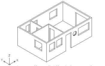
Figure A.10: The finished cabin walls solid, after a Hide
You are still looking at one object, the walls solid. Solids that represented doorway and window openings and spaces in rooms have been subtracted from it.
Creating a Floor for the Cabin
In designing our cabin, we didn’t draw a floor, but one was implied. The three exterior doorway openings have thresholds that indicate a change in level from the cabin floor down to the steps and the balcony. We’ll now use those thresholds to make a 3D solid for the floor.
- Continuing from the previous set of steps, click the Layer Properties Manager icon on the Object Properties toolbar and do the following:
- Create a new layer called 3D-Floor, assign it a brownish color, and make it current.
- Freeze the 3D-Walls and 3D-Windows layers, and turn off the Windows layers.
- Turn on the Walls and Steps layers.
The drawing will look like Figure A.11. If lines are missing, choose View Regen to regenerate all the lines. We’re going to create a series of solid primitives with the Box command that will represent parts of the floor. Then we’ll combine them.
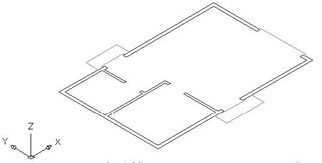
Figure A.11: The walls and steps in 2D
- Use the Zoom Window tool to set up a view of the front door opening and its threshold.
- Start the Box command and create a box that sits in the opening, between the jamb lines. Give it a height of 2". Then make a second box, also 2" high, that sits on the threshold overhang (see Figure A.12).
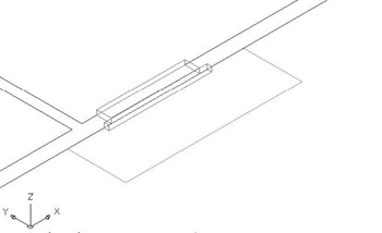
Figure A.12: The front door opening with two solid boxes - Repeat step 3 for the back door and the sliding glass door openings. Then make similar boxes that fit in the bedroom and bathroom door openings.
- Finally, make 2"-high boxes for the three rooms, using the inside corners and Endpoint Osnap. There will be two boxes for the living room. You will end up with 12 boxes (see Figure A.13).
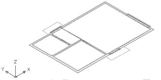
Figure A.13: The full floor with 12 solid boxes - Turn off the Walls and Steps layers. Choose Modify Solids Editing Union, and then use a selection window to select all the boxes. Press . The 12 boxes unite to form a 2"-thick floor solid (see Figure A.14).
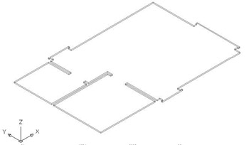
Figure A.14: The 12 boxes unite to form a new floor solid object. - Start the Move command, select the floor, and press .
- Click any blank location on the drawing area, and then type @0,0,10. The floor will be moved up 10".
- Thaw the 3D-Walls layer. Choose View 3D Views SE Isometric.
- Choose View Hide. The drawing should look like Figure A.15.
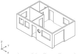
Figure A.15: The 3D walls and floor after a Hide
Forming the Steps and the Balcony in 3D
The steps require only a new layer and two boxes.
- Make a new layer called 3D-Steps, assign it color number 8, and make it current.
- Freeze the 3D-Walls and 3D-Floor layers, and turn on the Walls and Steps layers.
- Use the Box command to make a 10"-high box for the front and back steps (see Figure A.16). If the screen doesn’t display what is illustrated in Figure A.16 or what you expect, choose View Regen.
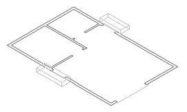
Figure A.16: The front and back steps as 3D solids
For the balcony, we’ll use the cylinder primitive and the Subtract Solids editing command.
- Make another new layer called 3D-Balcony, assign it color number 24, and make it current. Zoom in to the area around the balcony, leaving a little extra room for the 3D view. Turn on the Balcony layer.
- Choose the Cylinder tool to create a cylinder solid to represent the space enclosed by the balcony wall. Use Center Osnap to locate the center at the center point of the arcs that represent the balcony wall. Select a radius of 4'-6" and a height of 3'-2".
- Move this cylinder up 10" (see Figure A.17a).
- Draw a second cylinder using the same center point, with a radius of 5' and a height of 4'.
- Choose Modify Solids Editing Subtract. Select the larger cylinder, press , select the smaller cylinder, and press . A shape that looks like a bowl or a hot tub is created (see Figure A.17b).
- Click the Slice button on the Solids toolbar, select the balcony, and press .
- At the first prompt, type yz. This defines the plane that we’ll use to slice the balcony.
- At the second prompt, pick the bottom corner of the cabin wall, where the bottom of the balcony meets the corner. This positions the yz cutting plane in line with the exterior wall surface that the balcony wall butts against.
- At the third prompt, click a blank spot below and to the right of the balcony. This tells AutoCAD the side of the cutting plane where the desired objects are. The shape is cut in half, the inside half is deleted, and the balcony is complete (see Figure A.17c).
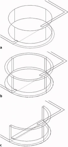
Figure A.17: The first cylinder of the balcony (a), the balcony solid after subtraction (b), and the finished balcony after using the Slice tool (c) - Zoom Previous, turn off the Balcony, Walls, and Steps layers, and thaw the 3D-Walls and 3D-Floor layers. Then choose View Hide (see Figure A.18a). Note the series of flat, triangular surfaces that compose the curved surface of the balcony.
- Choose View Shade Gourard Shaded, Edges On. This type of shading blends the shades of two adjacent surfaces that define a curve at their adjoining edges and creates a realistic appearance (see Figure A.18b).
- Choose View 3D Orbit. A green circle called an arcball is superimposed over your 3D model. There are smaller circles at the quadrant points of the larger circle. This is a viewing tool in which the view of the 3D model is controlled by the movement of the cursor. How the cabin moves in 3D space depends on whether you click and drag inside or outside the big circle or within one of the small circles.
- Place the cursor inside the circle, and then click and hold down the left mouse button. As you move the cursor, the model turns in space. Release the mouse button to fix a view (see Figure A.18c). Play around with this feature for a bit.
- When finished, right-click and choose Reset View from the shortcut menu. Choose View Shade 2D Wireframe to restore the view to that of the wireframe.
The 3D model is taking shape. To finish it, we will add doors, windows, and the roof.
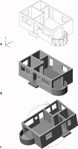
Figure A.18: The balcony, walls, and floor after a Hide (a), after using the Shade command (b), and while using 3D Orbit (c)
Finishing the 3D Model
The 3D solids of the swinging doors are constructed with the box primitive that we have been using. There is no need for any step-by-step instructions here. Just follow the same procedure that you did for creating the floor, steps, and balcony. You can use the 3D-Doors layer that you created earlier for the openings, but change its color to No. 34. Construct the swinging doors over the 2D doors on the Door layer, with a height of 6'-51⁄2". Then move them up 121⁄2". Use the Shade command and the 3D Orbit tool to check your work.
The sliding glass door and the windows are similar in construction. They both have a frame and a piece of glass held in the frame. Once we do the sliding glass door, you can apply the same method to the windows. Our strategy will be to create a frame by subtracting a smaller box from a larger one. Refer to Chapter 4 for the dimensions of the opening. The frames are 2" wide and 11⁄2" thick.
- Set the view to SE Isometric (choose View 3D Views).
- Turn on the Doors layer and freeze all 3D layers except 3D-Walls and the current layer, 3D-Doors.
Remember: to make 3D layers invisible, freeze them. This ensures that Hides will display properly.
- Zoom in to the sliding glass door panel that is closest to the corner (see Figure A.19a).
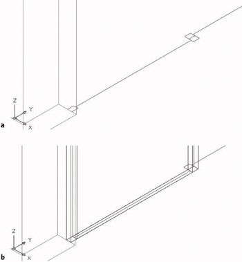
Figure A.19: A close view of one sliding glass door panel (a) and two new box solids on the 2D view of the panel (b) - Use the Box tool to make a solid box that sits on the outside corners of the door panel frame, with a height of 6'-6".
- Make a second box that sits inside the frame. To do this, snap to the opposite inside corners of the little rectangles that represent the frame. Give this box a height of 6'-2" (see Figure A.19b).
- Move the smaller box up 2" (in the positive Z direction).
- Subtract the smaller box from the larger one.
- Create a new layer called 3D-Glass, assign it color 151, and make it current.
- Choose Draw Surfaces 3D Face.
A 3D Face is a three- or four-sided two-dimensional surface object that turns opaque in a Hide.
- Set Midpoint to be the only running Osnap, and then click the midpoints of the lines representing the lower inside corners of the frame (see Figure A.20a).
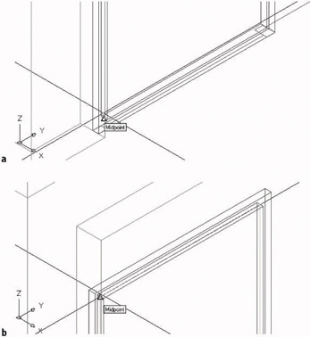
Figure A.20: Beginning the 3D face at the bottom of the frame (a) and finishing it at the top of the frame (b) - Pan up and pick the midpoints of the upper inside corners of the frame in a circular fashion to complete the 3D face (see Figure A.20b). Press to end the 3D Face command.
- Zoom Previous until you are back at the view of the bottom of the frame. Make Endpoint the only running Osnap, and copy the frame and glass to the other sliding glass door panel.
- Zoom out to a view of the whole opening, and then move the two doors with their glass up 12".
- Turn off the Doors layer, and thaw all 3D layers except 3D-Balcony. Use Hide to get a view of the completed sliding glass door in 3D (see Figure A.21).
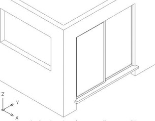
Figure A.21: The completed sliding glass door
By keeping the glass as a separate object on its own layer, we can make it invisible while leaving the frame unchanged, to allow us to look through the window. You can move either panel to give the appearance that the door has been slid open.
You can use this same technique to create the windows. The frames can be constructed in place (in the window openings), and the glass installed in the frames. If you use two frames, as you did for the sliding glass door (but in this case, one above the other), they will look like double-hung windows. If only one panel is used, the window will appear to be fixed in place.
Figure A.22 shows a partial view of the cabin. The front living room window is fixed in place, and the bathroom window is double hung. The bathroom window has the addition of a sill at the bottom of the opening.
Figure A.22: A partial view that shows two windows and the sliding glass door
Putting a Roof on the Cabin
We’ll finish the 3D model of the cabin by constructing a roof. The edge of the roof will be a different color than the roof surface, so we’ll make them as two separate objects, each on its own layer. The edge will be a solid, and the sloping part will be a set of surfaces.
- Create two new layers: 3D-Roof_Edge with color 32, and 3D-Roof with color 114. Make 3D-Roof_Edge current.
- Freeze all 3D layers except the two new ones, and turn off all other layers except Roof. Choose View 3D Views SE Isometric. Just the roof will be visible. (If it’s not, the Roof layer may be frozen, so thaw it.)
- Use the Box icon on the Solids toolbar to make a box that is 6" high and sits on the four corners of the roof (see Figure A.23a).
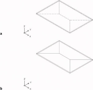
Figure A.23: The solid box is made (a) and the copied roof lines are moved to the 3D-Roof_Edge layer (b). - Move the box up 9'. Then copy the ridge line and hip lines of the roof up to the top edge of the box.
- Use Properties to change these copied lines to the 3D-Roof_Edge layer. Then turn off the Roof layer (see Figure A.23b).
- Start the Stretch command (on the Modify toolbar), and use a crossing window to select just the ridge line and the ends of the four hip lines that touch the ridge line.
- Press . Click a blank part of the drawing area for the base point, and then type @0,0,3'. The roof is stretched up 3' (see Figure A.24a).
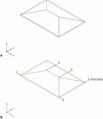
Figure A.24: The ridge and hip lines are stretched up (a) and the sequence of picks for the first two 3D Faces (b) - Make the 3D-Roof layer current, and then choose Draw Surfaces 3D Face.
- With Endpoint Osnap, start at the leftmost corner of the sloping planes and pick the four corners of the front plane of the roof. Then, at the Specify third point or [Invisible] <exit>: prompt, move to the rightmost corner and click this point twice. Follow the diagram in Figure A.24b. Press to end the 3D Face command.
- Repeat steps 8 and 9 for the back and left surfaces of the roof.
- Momentarily turn off the 3D-Roof layer, erase the ridge and hip lines, turn the 3D-Roof layer back on again, and thaw all 3D layers except the 3D-Glass layer.
- Zoom to Extents, and then choose View Hide to view the cabin (see Figure A.25).
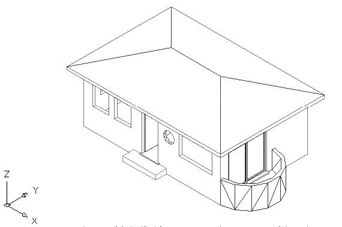
Figure A.25: The completed cabin after a Hide - Use the Shade options and 3D Orbit to view the model in color and at different angles.
- Save this file as CabinA1.
Further Directions in 3D
Covering 3D in real depth is beyond the scope of this book, but I can mention a few other tools and features that you might enjoy investigating. First, I’ll summarize a few of the solids and surface modeling tools that I didn’t cover in the tutorial on the cabin. Then we will take a quick look at the rendering process as it is approached in AutoCAD.
Other Solids Modeling Tools
We used the Box and Cylinder primitive solid tools to build up the model of the cabin. There are four other primitive shapes, all found on the Solids toolbar:
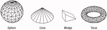
SphereYou specify the center point and radius or diameter.
ConeYou specify the center point of the base, the radius of the base, and the height of the pointed tip. The base is parallel to the XY plane, and the height is perpendicular to it.
WedgeIt has a rectangular base and a lid that slopes up from one edge of the base. You specify the base as you do in the Box tool and then enter the height.
TorusThis is a donut. You specify a center point for the hole, the radius of the circular path that the donut makes, and the radius of the tube that follows the circular path around the center point.
Two other tools exist for creating solids by moving 2D shapes in the third dimension:
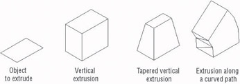
ExtrudeSelect a closed 2D shape such as a rectangle or a circle. Then specify a height of the extrusion or a path to extrude along. If the extrusion is straight up, you enter an angle to taper the edges away from the vertical.
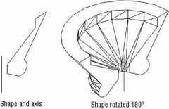
RevolveSelect a closed 2D shape, and then define the axis and the angle of rotation.
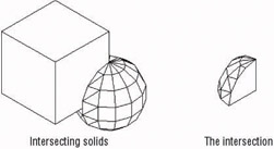
There are many tools for modifying solids. When we formed the cabin walls, floor, and balcony, we used Union and Subtract, as well as Slice. Another solids editing tool, Intersect, finds the volume that two solids have in common when they partially occupy the same space. It’s at the top of the Modify Solids Editing menu, with Union and Subtract. Click the solids that are “colliding,” and AutoCAD creates a solid from their intersection.
These are only a few of the many tools for creating and modifying solids, but should be enough to get you started.
Surface Modeling Tools
Surface modeling has its own set of tools, some of which are similar to those for solid modeling. Choose Draw Surfaces 3D Surfaces to open the 3D Objects dialog box.
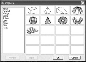
Most of these shapes are the same as, or vary slightly from, the six primitive solid shapes. But 3D Surface objects can’t be joined using the Union, Subtract, and Intersection tools. Here is a brief description of a few of the other tools on the Surfaces menu.
In the 3D Objects dialog box, selecting Mesh creates a rectangular three-dimensional surface mesh when you pick four points in 3D space and specify the number of divisions of faces.
When you choose Draw Surfaces, you have the following choices at the bottom of the submenu:
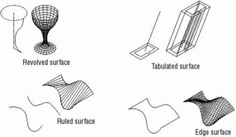
Revolved SurfaceCreates a 3D surface mesh by rotating a 2D curved line around an axis of revolution.
Tabulated SurfaceCreates a 3D surface mesh by extruding a 2D object in a direction determined by the endpoints of a line, an arc, or a polyline.
Ruled SurfaceCreates a 3D surface mesh between two selected shapes.
Edge SurfaceCreates a 3D surface mesh among four lines that are connected at their endpoints. Each line can be in 2D or 3D, and the original shape must be a boundary of a shape that does not cross or conflict with itself.
Most 3D models today use the solid modeling tools for their basic shapes because the tools for adding, subtracting, slicing, and so forth are easy to use and allow complex shapes to be fabricated quickly. Still, surface modeling has its uses, and sometimes a shape will lend itself to surface over solid modeling. Any serious 3D modeler will be familiar with both sets of tools.
Rendering with AutoCAD
The next step after developing a 3D model is to render it. This process has several parts:
- Setting up a 3D view of the scene to be rendered
- Creating a lighting scheme
- Enabling and controlling shadow effects
- Assigning material textures to surfaces
- Possibly choosing a background view
- Putting in auxiliary objects such as people and trees
- Saving setup views and lights as restorable scenes
- Outputting a rendering to a file
In this appendix, I’ll just give you a quick tour of some of these rendering steps, as we set up a view of the cabin and render it. Developing a full rendering takes time and patience, but touching on a few of the many steps involved will give you a feel for the process. You have put in a lot of time working your way through this book, and you deserve to have a rendered 3D view of your cabin, however simple, to complete the process.
Setting Up a 3D View to Render
We’ll create a rectangle to serve as the land the cabin sits on, and then we’ll adjust our view.
- With CabinA1 as the current drawing, type ucs, and then press twice to return to the World Coordinate System, if you weren’t already there.
- Choose View 3D Views Plan View World UCS to return to a plan view of your drawing. Turn off the UCS icon.
- Create a new layer called 3D-Land, assign it color 74, and make it current.
- Zoom out and create a rectangle around the cabin that is 160' wide and 140' high. To be sure the rectangle is created at “ground level,” don’t snap to any parts of the cabin.
- Move that rectangle to a position relative to the cabin approximately as shown in Figure A.26. Again, don’t snap to any parts of the cabin yet.
Figure A.26: A plan view with the rectangle around the cabin - Choose Draw Region, select the rectangle, and then press . This creates a 2D object called a region that behaves like a 3D object. It turns opaque in a Hide, Shade, or Render, and holes can be cut out of it.
- Choose View 3D Views SE Isometric. This is one of the standard 3D views we used to construct the 3D model of the cabin. Now we’ll modify it slightly.
- Choose View 3D Views Viewpoint Presets to open the Viewpoint Presets dialog box. Here you can fine-tune the rotation of the view in the XY plane and the angle of the view relative to the XY plane. The rotation is all right, but we will make the angle flatter.
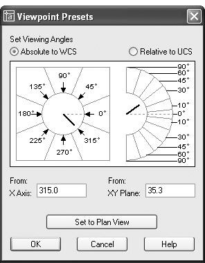
- On the right, in the XY Plane text box, change 35.3 to 5, and then click OK.
A standard isometric view uses an angle relative to the XY plane of 35.3.
- Use a Zoom Window to bring the cabin in closer, as shown in Figure A.27.
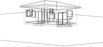
Figure A.27: A close view of the cabin after zooming in - Pan the view down so only the back lines of the rectangular region are visible.
- Be sure all 3D layers are thawed and turned on.
- Select View 3D Orbit. Right-click in the drawing area, and choose Projection Perspective. Exit 3D Orbit. This completes the view setup for the render (see Figure A.28).
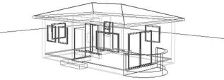
Figure A.28: The view ready to be rendered
Creating a Light Source
Here are AutoCAD’s three kinds of lighting and their equivalents:
- Point Light, a hanging light bulb
- Distant Light, the sun
- Spotlight, a floodlight
Each has unique setup parameters. We’ll set up a Distant light, which will light the cabin as the sun would. To do this, we have to march through a series of dialog boxes.
- Display the Render toolbar and let it float in the drawing area. On this new toolbar, click the Lights button to open the Lights dialog box (see Figure A.29).
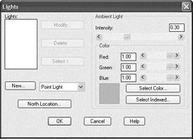
Figure A.29: The Lights dialog box - On the left side, next to the New button, open the drop-down list and select Distant Light. Then click the New button to open the New Distant Light dialog box (see Figure A.30).
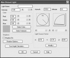
Figure A.30: The New Distant Light dialog box - Enter Sunlight for the Light Name, and then click the Sun Angle Calculator button to open the Sun Angle Calculator dialog box (see Figure A.31).
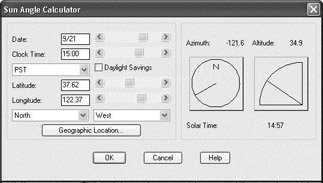
Figure A.31: The Sun Angle Calculator dialog box - Change the date to 9/8 and the time to 11:00, and then click the Geographic Location button to open the Geographic Location dialog box (see Figure A.32).
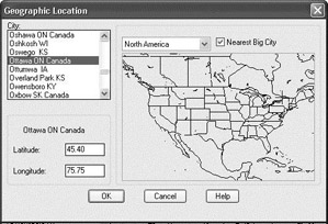
Figure A.32: The Geographic Location dialog box - In the drop-down list above the map, select North America. Then scroll down the list of cities on the left, and select San Francisco, CA. Click OK to close this dialog box.
- Click OK twice more to get back to the Lights dialog box (see Figure A.29, shown earlier). In the Ambient Light area, change the intensity from .30 to .50. You can change the Intensity setting by using the scroll bar or by typing it. Then click OK to return to your drawing.
Enabling Shadows
To control shadows, you have to make a few choices and adjust several settings. Shadows can be soft- or hard-edged, and you can calculate them using a couple of methods. This part of the rendering process is too technical to go into in this book, but you can follow along and end up with at least one setup for shadows that will enhance the rendering of the cabin.
- Click the Lights button on the Rendering toolbar to bring back the Lights dialog box.
- With Sunlight highlighted, click the Modify button to open the Modify Distant Light dialog box. It’s almost identical to the New Distant Light dialog box in Figure A.30 (shown earlier).
- In the Shadows area, put a check mark in the Shadow On box. Then click the Shadow Options button to open the Shadow Options dialog box (see Figure A.33).
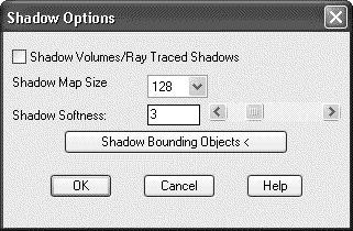
Figure A.33: The Shadow Options dialog box - Put a check mark in the Shadow Volumes/Ray Traced Shadows box, and then click OK. This will give the shadows harder edges.
- Click OK to return to the Lights dialog box. Then click OK again to return to the drawing. When we start to render, we will have a few more changes to make for the shadows.
The First Render
Let’s make the adjustments for shadows and then make a preliminary render. We’ll then add a background and try again. First, we need to check our layers to be sure they are colors that render well. The following is a list of the 3D layers and the colors that I have found work well with a white background in the drawing area for the rendering that we are setting up here.
|
Layer |
Color |
|---|---|
|
3D-Balcony |
24 |
|
3D-Doors |
34 |
|
3D-Floor |
42 |
|
3D-Glass |
132 |
|
3D-Land |
76 |
|
3D-Roof |
250 |
|
3D-Roof-Edge |
32 |
|
3D-Steps |
8 |
|
3D-Walls |
40 |
|
3D-Windows |
22 |
These colors don’t all match the colors that I instructed you to assign to these layers as we were building the 3D model earlier in this appendix. You can save the current assignments by using the Save Layer States Manager button in the Layer Properties Manager dialog box. Then, for the rendering, change the colors to match the table.
- Click the Render button on the Render toolbar to open the Render dialog box (see Figure A.34).
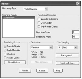
Figure A.34: The Render dialog box - At the top, be sure the Rendering Type drop-down list displays Photo Raytrace.
- In the Rendering Options area, put a check mark in the Shadows box.
- Click the Render button. After a few moments, the rendering appears (see Figure A.35).
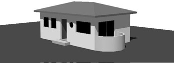
Figure A.35: The preliminary render
The building looks fine, but it would be nice to have something in the background other than the blank screen.
Controlling the Background of the Rendering
The following are some of the options in choosing a background for the rendering:
The AutoCAD BackgroundThis is what we used for the preliminary rendering.
Another Solid ColorYou use slide bars to choose it.
A GradientYou can use varying colors (usually light to dark) blended together.
An ImageYou can supply or choose a bitmap image.
We’ll choose the last option and use a file that is supplied with AutoCAD.
- Click the Background button on the Render toolbar to open the Background dialog box (see Figure A.36).
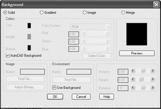
Figure A.36: The Background dialog box - The four radio buttons across the top determine the kind of background. Click the Image radio button; then in the Image area, click the Find File button to open the Background Image dialog box (see Figure A.37). It’s a Select File type of dialog box.
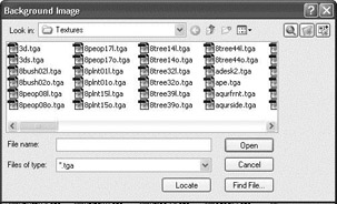
Figure A.37: The Background Image dialog box - Navigate to the Textures subfolder. Here is the path if you need it: C:Documents and Settingsyour nameLocal SettingsApplication DataAutodeskAutoCAD 2005R 16.0enuTextures. Open the Files Of Type drop-down list and select the *.tga type. Quite a few .tga files are listed.
- Find valley_1.tga and select it, then click Open. Back in the Background dialog box, the file and its path will be displayed in the Name text box in the Image area.
- Click OK to close the Background dialog box.
- Click the Render button on the Render toolbar, and then click the Render button in the Render dialog box. Your rendering now has a photographic scene as a background (see Figure A.38). The lighting on the cabin is slightly different from that in the photograph, but the overall effect works well enough.
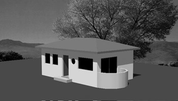
Figure A.38: The complete rendered scene
Now you need to save this view and this rendering.
Saving a Rendering Setup
You need to save two things in order to re-create this rendering at a later time: the view that was set, and the light or lights that were used for the rendering. First, we’ll save the view, and then we’ll save the view and distant light as a scene.
- Choose View Named Views to open the Views dialog box.
- Click the New button. In the New View dialog box, enter Render1 for the view name. Click the Current Display radio button, and then click OK. The view is saved and now displayed in the list of views. Click OK again to close the Views dialog box.
- Click the Scenes button on the Render toolbar to open the Scenes dialog box. Click the New button to open the New Scene dialog box. In the left box, views are listed; in the right, the one light we have set up is listed (see Figure A.39).
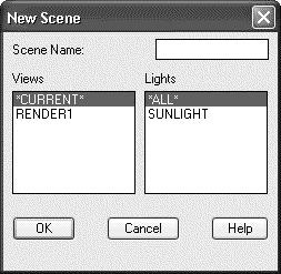
Figure A.39: The New Scene dialog box - Enter Scene_A in the Scene Name box. Select Render1 under Views, select Sunlight under Lights, and then click OK. You are returned to the Scenes dialog box. Scene_A is now on the list (see Figure A.40). Click OK.
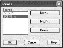
Figure A.40: The Scenes dialog box with Scene_A listed
Now you can change the view and add new lights to create a second scene.
Rendering to a File
The Render feature creates a rendering on the drawing area. The picture itself can’t be saved (except by a screen grab), but we can re-render the scene to a file. Then it is saved and can be viewed by various applications.
- Click the Render button on the Render toolbar. In the Render dialog box, go to the Destination area, open the drop-down list, and select File. Then click the More Options button that is in the same area to open the File Output Configuration dialog box (see Figure A.41).
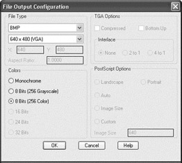
Figure A.41: The File Output Configuration dialog box - Set your preference for the file type, pixel size, color, and so on, and then click OK.
- Back in the Render dialog box, click the Render button to open the Rendering File dialog box.
- Designate a folder and a name, and then click Save. The scene is rendered and saved to the chosen folder.
Trying Another View
Let’s finish by changing our view and turning off a layer to see a slightly different result.
- Freeze the 3D-Glass layer.
- Choose View 3D Orbit.
- Change the view of the cabin so that it’s a little flatter and you can see through windows and doors into the cabin and out to the background scene.
- Right-click and choose Projection Perspective. (Perspective may already be selected.)
- Right-click again and choose Exit.
- Click the Render button on the Render toolbar.
- In the Scene To Render area, select Current View.
- In the Destination area of the Render dialog box, open the drop-down list and select Viewport. Then click the Render button in the dialog box. AutoCAD renders this scene (see Figure A.42).
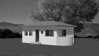
Figure A.42: The second rendered scene - If the view or lighting needs modification, make the change and try another render. If you like the results, re-render the scene to a file. Save the view as a named view, and then save the view and lights as a scene.
This has been a brief introduction into the world of 3D and rendering in AutoCAD, but you should now be oriented to the general way of doing things and have enough tools to experiment further. For a more in-depth discussion of the entire process, including rendering, see Mastering AutoCAD 2005 and AutoCAD LT 2005 (Sybex, 2004) by George Omura.
Introduction
- Getting to Know AutoCAD
- Basic Commands to Get Started
- Setting Up a Drawing
- Gaining Drawing Strategies: Part 1
- Gaining Drawing Strategies: Part 2
- Using Layers to Organize Your Drawing
- Grouping Objects into Blocks
- Generating Elevations
- Working with Hatches and Fills
- Controlling Text in a Drawing
- Dimensioning a Drawing
- Managing External References
- Using Layouts to Set Up a Print
- Printing an AutoCAD Drawing
- Appendix A Look at Drawing in 3D
EAN: N/A
Pages: 159
- ERP System Acquisition: A Process Model and Results From an Austrian Survey
- The Effects of an Enterprise Resource Planning System (ERP) Implementation on Job Characteristics – A Study using the Hackman and Oldham Job Characteristics Model
- Data Mining for Business Process Reengineering
- Relevance and Micro-Relevance for the Professional as Determinants of IT-Diffusion and IT-Use in Healthcare
- Development of Interactive Web Sites to Enhance Police/Community Relations
