Gaining Drawing Strategies: Part 1
Gaining DrawingStrategies Part 1
Overview
- Making interior walls
- Zooming in on an area using various zoom tools
- Making doors and swings
- Using Object Snaps
- Using the Copy and Mirror commands
Assuming that you have worked your way through the first three chapters, you have now successfully drawn a box (Chapter 2) as well as the outer wall lines of the cabin (Chapter 3). From here on, you will develop a floor plan for the cabin and in Chapter 8, elevations (views of the front, back, and sides of the building that show how the building will look if you’re facing it). The focus in this chapter is on gaining a feel for the strategy of drawing in AutoCAD and on how to solve drawing problems that come up in the course of laying out the floor plan. As you work your way through this chapter, your activities will include making the walls, cutting doorway openings, and drawing the doors (see Figure 4.1). In Chapter 5, you will add steps and a balcony and place fixtures and appliances in the bathroom and kitchen.
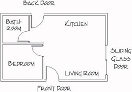
Figure 4.1: The basic floor plan of the cabin
Each exercise in this chapter presents opportunities to practice using commands you already know from previous chapters and to learn a few new ones. The most important goal is to begin to use strategic thinking as you develop methods for creating new elements of the floor plan.
Laying Out the Walls
For most floor plans, the walls come first. The first lesson in this chapter is to understand that you will not be putting many new lines in the drawing, at least not as many as you might expect. You will create most new objects in this chapter from items already in your drawing. In fact, you will draw no new lines to make walls. You’ll generate all new walls from the four exterior wall lines you drew in the last chapter.
You will need to create an inside wall line for the exterior walls (because the wall has thickness) and then make the three new interior walls (see Figure 4.2). The thickness will be 4" for interior walls and 6" for exterior walls, because exterior walls have an additional layer or two of weather protection, such as shingles or stucco. Finally, you will need to cut five openings in these walls (interior and exterior) for the doorways.
All the commands used for this exercise were presented in Chapters 2 and 3. If you need a refresher, glance back at these chapters.
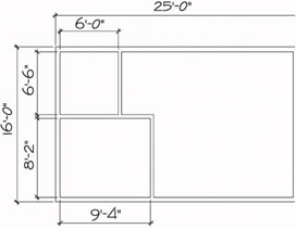
Figure 4.2: The wall dimensions
The Exterior Wall Lines
The first step is to offset the existing four wall lines to the inside to make the inside wall lines for the exterior walls. You will then need to fillet them to clean up their corners, just like you did for the box in Chapter 2.
This procedure is identical to the one you performed in Chapter 2 on the box.
| Tip |
Buildings are usually—but not always—dimensioned to the outside edge of exterior walls and to the center line of interior walls. Wood-frame buildings are dimensioned to the outside edges of their frames and to the center lines of the interior walls. |
- If AutoCAD is already running, choose File Open. In the Select File dialog box, navigate to the folder you designated as your training folder and select your cabin drawing. (You named it Cabin03.dwg at the end of Chapter 3.)
If you are starting AutoCAD and if you have chosen Do Not Show A Startup Dialog on the System tab of the Options dialog box, follow the instructions at the beginning of step 1.
Then click Open. If you are starting AutoCAD, and if you have chosen Show Startup Dialog Box on the System tab of the Options dialog box, the Startup dialog box opens. Be sure the Open A Drawing button is selected, and then look for the Cabin03 drawing in the Select A File list box. This box keeps a list of the most recently opened .dwg files.
Highlight your .dwg file and click OK. If you don’t find your file in the list, click the Browse button to open the Select File dialog box. Find and open your training folder, select your drawing file, and click Open. The drawing should consist of four lines making a rectangle (see Figure 4.3).
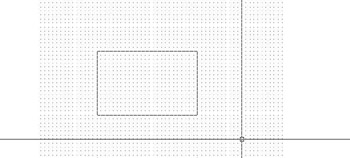
Figure 4.3: The cabin as you left it in Chapter 3 - On the status bar, click the Grid and Snap buttons to turn them off. Then start the Offset command by clicking the Offset button on the Modify toolbar.
- At the Offset distance: prompt, type 6.
Note You do not have to enter the inch sign ("), but you are required to enter the foot sign (').
- At the Select object to offset: prompt, click one of the four lines.
- Click in a blank area inside the rectangle. The first line is offset 6" to the inside (see Figure 4.4). The Offset command is still running, and the Select object to offset: prompt is still in effect.

Figure 4.4: The first line is offset. - Select another outside wall line and click in a blank area on the inside again. Continue doing this until you have offset all four outside wall lines to the inside at the set distance of 6". Then press to end the Offset command (see Figure 4.5). Now you will clean up the corners with the Fillet command.

Figure 4.5: All four lines are now offset 6" to the inside. - Start the Fillet command by clicking the Fillet button on the Modify toolbar.
- Look at the Command window to see whether the radius is set to zero. If it is, go on to step 9. Otherwise, type r, and then type 0 to set the Fillet radius to zero.
- Click any two lines that form an inside corner. Be sure to click the part of the lines you want to remain after the fillet is completed.
(Refer to Chapter 2 to review how the Fillet command is used in a similar situation.) Both lines will be trimmed to make an inside corner (see Figure 4.6). The Fillet command automatically ends after each fillet.
Figure 4.6: The first corner is filleted. - Press or the spacebar to restart the Fillet command.
- Pick two more lines to fillet, and then restart the Fillet command. Continue doing this until all four corners are cleaned up (see Figure 4.7). After the last fillet, the Fillet command will end automatically.
You can restart the most recently used command by pressing the spacebar or at the Command: prompt or by right-clicking and choosing the first item on the shortcut menu that opens.
Figure 4.7: The four inside corners have been cleaned up.
Characteristics That Offset and Fillet Have in Common
- Both are on the Modify toolbar and on the Modify drop-down menu.
- Both have a default distance setting—offset distance and fillet radius—that you can accept or reset.
- Both require you to select object(s).
Characteristics That Are Different in Offset and Fillet
- You select one object with Offset and two with Fillet.
- Offset keeps running until you stop it. Fillet ends after each fillet operation, so you need to restart Fillet to use it again.
You will find several uses for Offset and Fillet in the subsequent sections of this chapter and throughout the book.
The Interior Walls
Create the interior wall lines by offsetting the exterior wall lines.
- At the Command: prompt, start the Offset command.
- At the Offset distance: prompt, type 9'4. Leave no space between the foot sign (') and the 4.
AutoCAD requires that you enter a distance containing feet and inches in a particular format: no space between the foot sign (') and the inches, and a hyphen (-) between the inches and the fraction. For example, if you are entering a distance of 6'-43⁄4", you type 6'4-3⁄4. The measurement is displayed in the normal way, 6'-43⁄4", but you must enter it in the format that has no spaces.
- Click the inside line of the left exterior wall (see Figure 4.8).
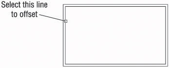
Figure 4.8: Selecting the wall line to offset - Click in a blank area to the right of the selected line. The line is offset 9'-4" to the right.
- Press twice, or press the spacebar twice. The Offset command is now restarted, and you can reset the offset distance.
Tip In the Offset command, your opportunity to change the offset distance comes right after you start the command. So if the Offset command is already running, and you need to change the offset distance, you need to stop and then restart the command. To do so, press or the spacebar twice.
- Type 4 to reset the offset distance.
- Click the new line that was just offset, and then click in a blank area to the right of that line. You have created a vertical interior wall (see Figure 4.9). Press twice to stop and restart the Offset command.
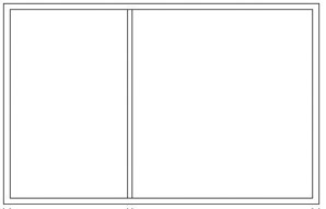
Figure 4.9: The first interior wall - Type 6.5' to set the distance for offsetting the next wall.
Note With Architectural units set, you can still enter distances in decimal form for feet and inches, and AutoCAD will translate them into their appropriate form. For example, you can enter 6'-6" as 6.5', and you can enter 1⁄2" as 4.5 without the inch sign. Remember, when entering figures, you can leave off the inch sign ("), but you must enter the foot sign (').
- Pick a point on the inside, upper exterior wall line (see Figure 4.10).
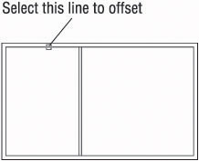
Figure 4.10: Selecting another wall line to offset - Click in a blank area below the line selected. The inside exterior wall line is offset to make a new interior wall line. Press the spacebar twice to stop and restart the Offset command.
- Type 4. Click the new line and click again below it. A second wall line is made, and you now have two interior walls. Press the spacebar to end the Offset command.
These interior wall lines form the bedroom and one side of the bathroom. You need to clean up their intersections with each other and with the exterior walls. If you take the time to do this now, it will be easier to make the last interior wall and thereby complete the bathroom. Refer to Figures 4.1 and 4.2 earlier in this chapter to see where we’re headed.
Cleaning Up Wall Lines
Earlier, you used the Fillet command to clean up the inside corners of the exterior walls. You can use that command again to clean up some of the interior walls, but you will have to use the Trim command to do the rest of them. You’ll see why as you progress through the next set of steps.
- It will be easier to pick the wall lines if you make the drawing larger on the screen. Type z, and then type e. Press , and then type .6x. The drawing is bigger. You’ve just used two options of the Zoom command: First, you zoomed to Extents to fill the screen with your drawing. You then zoomed to a scale (.6x) to make the drawing 0.6 the size it had been after zooming to Extents. This is a change in magnification on the view only; the building is still 25 feet long and 16 feet wide.
- Click the Fillet button on the Modify toolbar to start the Fillet command, and after checking the Command window to be sure that the radius is still set to zero, click two of the wall lines as shown in Figure 4.11a. The lines will be filleted, and the results will look like Figure 4.11b.

Figure 4.11: Selecting the first two lines to fillet (a), and the result of the fillet (b) - Press the spacebar to restart the Fillet command. Select the two lines as shown in Figure 4.12a. The results are shown in Figure 4.12b.
The best rule for choosing between Fillet and Trim is the following: If you need to clean up a single intersection between two lines, use the Fillet command. For other cases, use the Trim command.
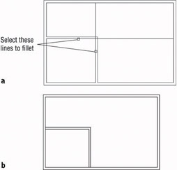
Figure 4.12: Selecting the second two lines to fillet (a), and the result of the second fillet (b)
The two new interior walls are now the right length, but you will have to clean up the areas where they form T intersections with the exterior walls. The Fillet command won’t work in T intersections because too much of one of the wall lines gets trimmed away. You’ll have to use the Trim command in T-intersection cases. The Fillet command does a specific kind of trim and is easy and quick to execute, but its uses are limited (for the most part) to single intersections between two lines.
Using the Zoom Command
To do this trim, you need a closer view of the T intersections. Use the Zoom command to get a better look.
- Type z. Then move the crosshair cursor to a point slightly above and to the left of the upper T intersection (see Figure 4.13), and click in a blank area outside the floor plan.
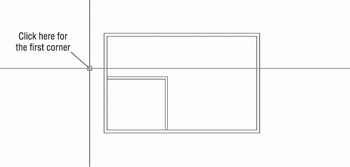
Figure 4.13: Positioning the cursor for the first click of the Zoom command - Move the cursor down and to the right, and notice a rectangle with solid lines being drawn. Keep moving the cursor down and to the right until the rectangle encloses the upper T intersection (see Figure 4.14a). When the rectangle fully encloses the T intersection, click again. The view changes to a closer view of the intersection of the interior and exterior walls (see Figure 4.14b).
When you start the Zoom command by typing z and then picking a point on the screen, a zoom window begins.
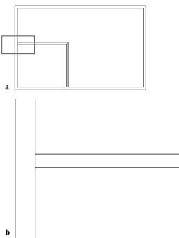
Figure 4.14: Using the zoom window option: positioning the rectangle (a), and the new view after the Zoom command (b)The rectangle you’ve just created is called a zoom window. The part of the drawing enclosed by the zoom window becomes the view on the screen. This is one of several zoom options for changing the magnification of the view. Other zoom options are introduced later in this chapter and throughout the book.
- On the Modify toolbar, click the Trim button. In the Command window, notice the second and third lines of text. You are being prompted to select cutting edges (objects to use as limits for the lines you want to trim).
- Select the two interior wall lines and press the spacebar. The prompt changes, now asking you to select the lines to be trimmed.
- Select the inside exterior wall line at the T intersection, between the two intersections with the interior wall lines that you have just picked as cutting edges (see Figure 4.15a). The exterior wall line is trimmed at the T intersection (see Figure 4.15b). Press the spacebar to end the Trim command.
In the Trim command, click the part of the line that needs to be trimmed away when picking lines to be trimmed. In the Fillet command, select the part of the line that you want to keep.
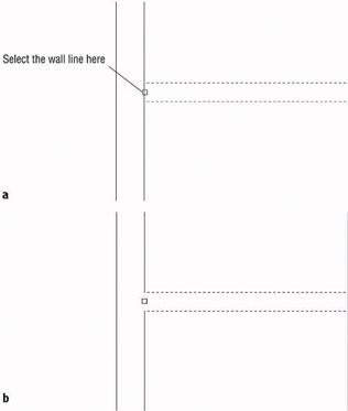
Figure 4.15: Selecting a line to be trimmed (a), and the result of the Trim command (b) - Return to a view of the whole drawing by typing z and then p. This is the Zoom command’s Previous option, which restores the view that was active before the last use of the Zoom command (see Figure 4.16).
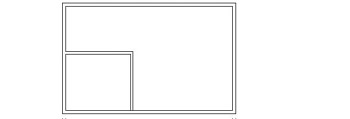
Figure 4.16: The result of the Zoom Previous command
Repeat this procedure to trim the lower T intersection. Follow these steps:
- Type z and click two points to make a rectangular zoom window around the intersection.
- Start the Trim command again, select the interior walls as cutting edges, and press the spacebar.
- Select the inside exterior wall line between the cutting edges.
- Press the spacebar or to end the Trim command.
- Zoom Previous by typing zp.
Figure 4.17 shows the results.

Figure 4.17: The second trim is completed.
You need to create one more interior wall to complete the bathroom.
Finishing the Interior Walls
You will use the same method to create the last bathroom wall that you used to make the first two interior walls. Briefly, this is how it’s done:
- Offset the upper-inside line of the left exterior wall 6' to the right; then offset this new line 4" to the right.
- Use Zoom Window to zoom into the bathroom area.
Tip Make a zoom window just large enough to enclose the bathroom. The resulting view should be large enough to allow you to trim both ends of the interior wall without re-zooming.
- Use the Trim command to trim away the short portion of the intersected wall lines between the two new wall lines. This can be accomplished in one use of the Trim command: once you select the new wall lines as cutting edges, you can trim both lines that run across the ends of the selected lines to those same cutting edges.
- Use Zoom Previous to restore the full view.
The results should look like Figure 4.18.
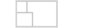
Figure 4.18: The completed interior walls
You used Offset, Fillet, Trim, and a couple of zooms to create the interior walls. The next task is to create five doorway openings in these walls. If you need to end the drawing session before completing the chapter, choose File Save As, and then change the name of this drawing to Cabin04a.dwg and click Save. You can then exit AutoCAD. To continue, do the same save and move on to the next section.
Cutting Openings in the Walls
Of the five doorway openings needed, two are on interior and three are on exterior walls (see Figure 4.19). Four of them will be for swinging doors, and one will be for a sliding glass door. We won’t be doing the hatchings and dimensions shown in the figure—those features will be covered in future chapters.
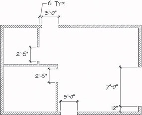
Figure 4.19: The drawing with doorway openings
The procedure used to make each doorway opening is the same one that you used to create the opening for the box in Chapter 2. First, you establish the location of the jambs, or sides, of an opening. One jamb for each swinging door opening will be located 6" from an inside wall corner. This allows the door to be positioned next to a wall and out of the way when swung open. When the jambs are established, you will trim away the wall lines between the edges. The commands used in this exercise are Offset, Extend, and Trim. You’ll make openings for the 3'-0" exterior doorways first.
The Exterior Openings
These openings are on the front and back walls of the cabin and have one side set in 6" from an inside corner.
- Click the Offset button on the Modify toolbar to start the Offset command, and then type 6 to set the distance.
- Click one of the two lines indicated in Figure 4.20, and then click in a blank area to the right of the line that you selected. Now do the same thing to the second wall line. You have to offset one line at a time because of the way the Offset command works.
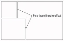
Figure 4.20: The lines to offset for 3'-0" openings - End and restart the Offset command by pressing the spacebar or twice; then type 3' to set a new offset distance, and offset the new lines to the right (see Figure 4.21). Next, you will need to extend these four new lines through the external walls to make the jamb lines.
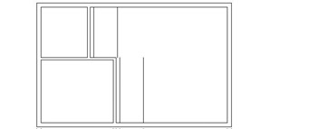
Figure 4.21: The offset lines for 3'-0" openings - Be sure to end the Offset command by pressing the spacebar or ; then start the Extend command. You use Extend here exactly as you used it in Chapter 2. Select the upper and lower horizontal outside, external wall lines as boundary edges for the Extend command, and press the spacebar or .
Tip If you start a new command by entering letters on the keyboard, you must first be sure that the previous command has ended. On the other hand, if you start a new command by clicking its icon on a toolbar or by choosing it from the menu bar, it doesn’t matter if the previous command is still running. AutoCAD will just cancel it.
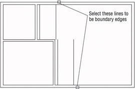
- Click the four lines to extend them. The lines are extended through the external walls to make the jambs (see Figure 4.22). End the Extend command by pressing the spacebar or .
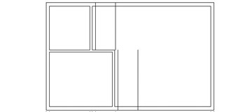
Figure 4.22: The lines after being extended through the external wallsTip You must pick the lines to be extended on the half of them nearest the boundary’s edge; if you do not, they will extend to the opposite boundary edge.
To complete the openings, we will continue with steps 6 and 7. First, we’ll trim away the excess part of the jamb lines, and then we’ll trim away the wall lines between the jamb lines. You’ll use the Trim command the same way you used it in Chapter 2, but this time you’ll do a compound trim to clean up the wall and jamb lines in one cycle of the command.
- Type tr to start the Trim command, and select the three lines at each opening (six lines total) as shown in Figure 4.23. Then press the spacebar or to tell AutoCAD you are finished selecting objects to serve as cutting edges.
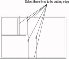
Figure 4.23: Selecting the cutting edges - Pick the four wall lines between the jamb lines, and then pick the jamb lines—the lines you just extended to the outside exterior walls, as shown in Figure 4.24.
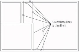
Figure 4.24: The lines to be trimmed - Each time you pick a line, it is trimmed. Press the spacebar or to end the command. Your drawing should look like Figure 4.25.

Figure 4.25: The finished 3'-0" openingsTip When picking lines to be trimmed, remember to pick the lines on the portion to be trimmed away.
You can construct the two interior openings using the same procedure.
The Interior Openings
These doorways are 2'-6" wide and also have one jamb set in 6" from the nearest inside corner. Figure 4.26 shows the three stages of fabricating these openings. Refer to the previous section on making openings for step-by-step instructions.
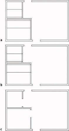
Figure 4.26: Creating the interior openings: the offset lines that locate the jamb lines (a), the extended lines that form the jamb lines (b), and the completed openings after trimming (c)
Construct the 7'-0" exterior opening using the same commands and technique.
The 7'-0" Opening
Notice that in Figure 4.19, earlier in this chapter, the opening on the right side of the building has one jamb set in 12" from the inside corner. This opening will be for the sliding glass door.
You’ve done this procedure before, so here’s a summary of the steps:
- Offset a wall line 12".
- Offset the new line 7'-0".
- Extend both new lines through the wall.
- Trim the new lines and the wall lines to complete the opening.
- Save this drawing as Cabin04b.dwg.
This completes the openings. The results should look like Figure 4.27.
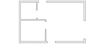
Figure 4.27: The completed doorway openings
As you gain more control over the commands you used here, you will be able to anticipate how much of a task can be done for each use of a command. Each opening required offsetting, extending, and trimming. You constructed these openings by drawing two at a time except for the last one, thereby using each of the three commands three times. It is possible to do all the openings using each command only once. In this way, you do all the offsetting, then all the extending, and finally all the trimming. In cutting these openings, however, the arrangement of the offset lines determined how many cycles of the Trim command were most efficient to use. If lines being trimmed and used as cutting edges cross each other, the trimming gets complicated. For these five openings, the most efficient procedure is to use each command twice. In Chapter 8, you’ll get a chance to work with more complex multiple trims when you draw the elevations.
Now that the openings are complete, you can place doors and door swings in their appropriate doorways. In doing this, you’ll be introduced to two new objects and a few new commands, and you’ll have an opportunity to use the Offset and Trim commands in new, strategic ways.
What to Do When You Make a Mistake
When you are offsetting, trimming, and extending lines, it’s easy to pick the wrong line. Here are some tips on how to correct these errors and get back on track:
- You can always cancel any command by pressing the Esc key until you see the Command: prompt in the Command window. Then click the Undo button on the Standard toolbar to undo the results of the last command. If you undo too much, click the Redo button. You can click it more than once to redo several undos.
- Errors made with the Offset command include setting the wrong distance, picking the wrong line to offset, or picking the wrong side to offset toward. If the distance is correct, you can continue offsetting, end the command when you have the results you want, and then erase the lines that were offset wrong. Otherwise, press Esc and undo your previous offset.
- Errors made with the Trim and Extend commands can sometimes be corrected on the fly, so you don’t have to end the command, because each of these commands has an Undo option. If you pick a line and it doesn’t trim or extend the right way, you can undo that last action without stopping the command and then continue trimming or extending. You can activate the Undo option used while the command is running in three ways: click the Undo button on the Standard toolbar; type u; or right-click and choose Undo from the shortcut menu that opens. Each of these will undo the last trim or extend, and you can try again without having to restart the command. Each time you activate the Undo option from within the command, another trim or extend is undone.
- The Line command also has the same Undo option as the Trim and Extend commands. You can undo the last segment drawn (or the last several segments) and redraw them without stopping the command.
Creating Doors
In a floor plan, a rectangle or a line for the door and an arc showing the path of the door swing usually indicates a swinging door. The door’s position varies, but it’s most often shown at 90 from the closed position (see Figure 4.28). The best rule I have come across is to display them in such a way that others working with your floor plan will be able to see how far, and in what direction, the door will swing open.
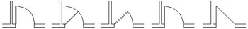
Figure 4.28: Possible ways to illustrate doors
The cabin has five openings. Four of them need swinging doors, which open 90. The fifth is a sliding glass door. Drawing it will require a different approach.
Drawing Swinging Doors
The swinging doors are of two widths: 3' for exterior and 2'-6" for interior (refer to Figure 4.1 earlier in this chapter). In general, doorway openings leading to the outside are wider than interior doors, with bathroom and closet doors usually being the narrowest. For the cabin, we’ll use two sizes of swinging doors. You will draw one door of each size and then copy these to the other openings as required. Start with the front door at the bottom of the floor plan. To get a closer view of the front door opening, use the Zoom Window command.
- Before you start drawing, check the status bar at the bottom of the screen and make sure only the Model button at the far right is pressed. All other buttons should be in the Off position—that is, up. If any are pressed, click them once to turn them off.
- Choose Tools Drafting Settings to open the Drafting Settings dialog box. Then click the Object Snap tab to activate it, if it’s not already on top.
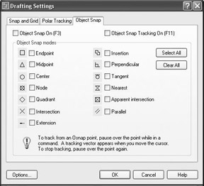
LT does not have the Extension and the Parallel Osnap modes, and it also does not have Object Snap Tracking.
- Be sure all check boxes are unchecked. If any boxes have check marks in them, click the Clear All button to uncheck them. Then click OK to close the dialog box.
- At the Command: prompt, move the cursor to the Standard toolbar and click the Zoom Window button.
- Pick two points to form a window around the front doorway opening, as shown in Figure 4.29a. The view changes, and you now have a close-up view of the opening (see Figure 4.29b). You’ll draw the door in a closed position and then rotate it open.
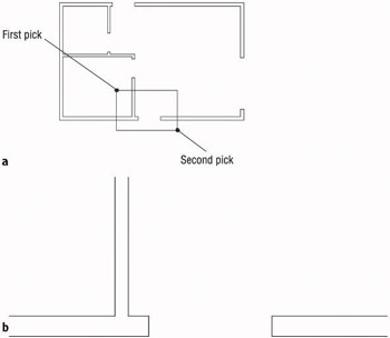
Figure 4.29: Forming a zoom window at the front door opening (a), and the result (b) - To draw the door, click the Rectangle button on the Draw toolbar.
You can also start the Rectangle command by choosing Draw Rectangle or by typing rec in the Command window.
Notice the Command window prompt. Several options are in brackets, but the option Specify first corner point (before the brackets) is the default and is the one you want. You form the rectangle in the same way that you form the zoom window—by picking two points to represent opposite corners of the rectangle. In its closed position, the door will fit exactly between the jambs, with its upper corners coinciding with the upper endpoints of the jambs. To make the first corner of the rectangle coincide with the upper endpoint of the left jamb exactly, you will use an Object Snap to assist you. Object Snaps (or Osnaps) allow you to pick specific points on objects such as endpoints, midpoints, the center of a circle, and so on.
- Type end. This activates the Endpoint Osnap for one pick.
Osnap is short for Object Snap. The two terms are used interchangeably.
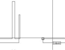
- Move the cursor near the upper end of the left jamb line. When the cursor gets very close to a line, a colored square appears at the nearest endpoint. This shows you which endpoint in the drawing is closest to the position of the crosshair cursor at that moment.
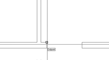
- Move the cursor until the square is positioned on the upper end of the left jamb line, as shown, and then click that point. The first corner of the rectangle now is located at that point. Move the cursor to the right and slightly down to see the rectangle being formed (see Figure 4.30a). To locate the opposite corner, let’s use the relative Cartesian coordinates discussed in Chapter 2.
Because of the way AutoCAD displays the crosshair cursor, both the lines and the crosshair disappear when its lines coincide with lines in the drawing. This makes it difficult to see the rectangle being formed.
- When the Command window shows the Specify other corner point or [Dimensions]: prompt, type @3',-1.5 in the command line. The rectangle is drawn across the opening, creating a door in a closed position (see Figure 4.30b). The door now needs to be rotated around its hinge point to an opened position.
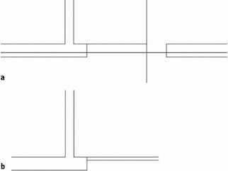
Figure 4.30: The rectangle after picking the first corner (a), and the completed door in a closed position (b)Note You could have used the Rectangle command to lay out the first four wall lines of the cabin in Chapter 3. Then you could have offset all four lines in one step to complete the exterior walls, and the corners would have been automatically filleted. It would have been faster than the method we used, but a rectangle’s lines are all one object. In order to offset them to make the interior walls, they would have to be separated into individual lines using the Explode command.
Rotating the Door
This rotation will be through an arc of 90 in the counterclockwise direction, making it a rotation of +90. By default, counterclockwise rotations are positive, and clockwise rotations are negative. You’ll use the Rotate command to rotate the door.
- Click the Rotate button on the Modify toolbar. You’ll see a prompt to select objects. Click the door and press .
Note When you select the door, one pick selects all four lines. Rectangles are made of a special line called a polyline that connects all segments into one object. You will learn more about them in Chapter 10.
You will be prompted for a base point—a point around which the door will be rotated. To keep the door placed correctly, pick the hinge point for the base point. The hinge point for this opening is the upper endpoint of the left jamb line.
- Type end.
- Move the cursor near the upper-left corner of the door. When the colored square is displayed at that corner, left-click to locate the base point.
- Check the status bar to be sure the Ortho button is not pressed. If it is, click it to turn Ortho off. When the Ortho button is on, the cursor is forced to move in a vertical or horizontal direction. This is useful at times, but in this instance such a restriction would keep you from being able to see the door rotate.
You can also start the Rotate command by choosing Modify Rotate on the drop-down menu or by typing ro.
- Move the cursor away from the hinge point, and see how the door rotates as the cursor moves (see Figure 4.31a). If the door swings properly, you are reassured that you correctly selected the base point. The prompt reads Specify rotation angle or [reference], asking you to enter an angle.
- Type 90. The door is rotated 90 to an open position (see Figure 4.31b).
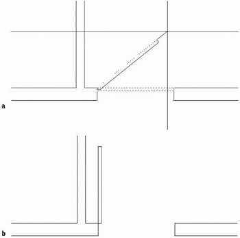
Figure 4.31: The door rotating with movement of the cursor (a), and the door after the 90 rotation (b)
To finish this door, you need to add the door’s swing. You’ll use the Arc command for this.
Drawing the Door Swing
The swing shows the path that the outer edge of a door takes when it swings from closed to fully open. Including a swing with the door in a floor plan helps to resolve clearance issues. You draw the swings using the Arc command, in this case using the Endpoint Osnap. This command has many options, most of which are based on knowing three aspects of the arc, as you will see.
- Choose Draw Arc to open the Arc menu. Ten of the 11 options have combinations of three aspects that define an arc. The arc for this door swing needs to be drawn from the upper end of the right jamb line through a rotation of 90. We know the start point of the arc, the center of rotation (the hinge point), and the angle through which the rotation occurs, so we can use the Start, Center, Angle option on the Arc menu.
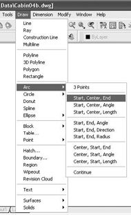
You can start abbreviated versions of the Arc command from the Draw toolbar or by typing a.
- From the Arc menu, choose Start, Center, Angle. The command prompt now reads _arc Specify start point of arc or [Center]:. The default option is Specify start point of arc. You can also start with the center point, but you have to typ e c before picking a point to be the center point.
- Activate the Endpoint Osnap (type end) and pick the upper endpoint of the right jamb line.
The prompt changes to read: Specify second point of arc or [Center/End]: _c Specify center point of arc.
This may be confusing at first. The prompt gives you three options: Second Point, Center, and End. (Center and End are in brackets.) Because you previously chose the Start, Center, Angle option, AutoCAD automatically chooses Center for you. That is the last part of the prompt.
- Activate the Endpoint Osnap again and select the hinge point. The arc is now visible, and its endpoint follows the cursor’s movement (see Figure 4.32a). The prompt displays a different set of options and then ends with the Included angle option.
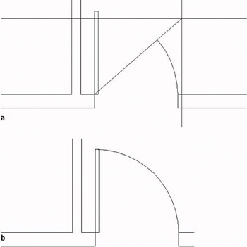
Figure 4.32: Drawing the arc: the ending point of the arc follows the cursor’s movements (a), and the completed arc (b) - Type 90. The arc is completed, and the Arc command ends (see Figure 4.32b).
The Options of the Arc Command
The position and size of an arc can be specified by a combination of its components, some of which are starting point, ending point, angle, center point, and radius. The Arc command gives you 11 options, 10 of which use 3 components. With a little study of the geometric information available to you on the drawing, you can choose the option that best fits the situation.
Choosing Draw Arc on the drop-down menu displays 10 options with their 3 components, and an 11th option is used to continue the last arc drawn. For that reason, this is the best way to start the Arc command when you are first learning it.
When you start the Arc command by clicking the Arc button on the Draw toolbar or by typing a, you get an abbreviated form of the command in the Command window. You can access all 11 options of the command through this prompt, but you have to select the various components along the way.
The front door is completed. Because the back door is the same size, you can save time by copying this door to the other opening. You’ll see how to do that next.
Copying Objects
The Copy command makes a copy of the objects you select. You can locate this copy either by picking a point or by entering relative coordinates from the keyboard. For AutoCAD to position these copied objects, you must designate two points: a base point, which serves as a point of reference for where the copy move starts; and then a second point, which serves as the ending point for the Copy command. The copy is moved the same distance and direction from its original that the second point is moved from the first point. When you know the actual distance and direction to move the copy, the base point isn’t critical because you will specify the second point with relative polar or Cartesian coordinates. But in this situation, you don’t know the exact distance or angle to move a copy of the front door to the back door opening, so you need to choose a base point for the copy carefully.
In copying this new door and its swing to the back door opening of the cabin, you need to find a point somewhere on the existing door or swing that can be located precisely on a point at the back door opening. There are two points like this to choose from: the hinge point and the start point of the door swing. Let’s use the hinge point. You usually know where the hinge point of the new door belongs, so this is easier to locate than the start point of the arc.
- Click the Copy button on the Modify toolbar. The prompt asks you to select objects to copy. Pick the door and swing, and then press . The prompt reads Specify base point or displacement, or [Multiple]:.
You can also start the Copy command by choosing Modify Copy on the drop-down menu or by typing cp.
Activate the Endpoint Osnap and pick the hinge point. A copy of the door and swing is attached to the crosshair cursor at the hinge point (see Figure 4.33). The prompt changes to Specify second point of displacement or <use first point of displacement>:. You need to pick where the hinge point of the copied door will be located at the back door opening. To do this, you need to change the view back to what it was before you zoomed into the doorway opening.
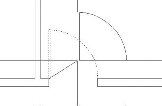
Figure 4.33: The copy of the door and swing attached to the crosshair cursor - From the Standard toolbar, click the Zoom Previous button to restore the full view of the cabin. Move the crosshair cursor with the door in tow up to the vicinity of the back door opening. The back door should swing to the inside and be against the wall when open, so the hinge point for this opening will be at the lower end of the left jamb line.
- Activate the Endpoint Osnap and pick the lower end of the left jamb line on the back door opening. The copy of the door and swing is placed in the opening (see Figure 4.34), and by looking at the Command window, you can see that the Copy command has ended.
The Copy command ends when you pick or specify the second point of the move, unless you’re copying the same object to multiple places. You’ll do that in Chapter 5 when you draw the stove top.
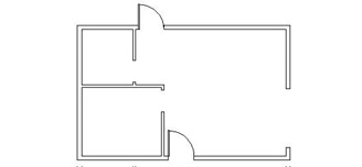
Figure 4.34: The door is copied to the back door opening.
The door is oriented the wrong way, but you’ll fix that next.
When you copy doors from one opening to another, often the orientation doesn’t match. The best strategy is to use the hinge point as a point of reference and place it where it needs to go, as you have just done. Then flip and/or rotate the door so that it sits and swings the right way. The flipping of an object is known as mirroring.
You were able to use the Zoom command while you were in the middle of using the Copy command. You can use most of the display commands (Zoom, Pan, and so on) in this way. This is called using a command transparently.
Mirroring Objects
You have located the door in the opening, but it needs to be flipped so that it swings to the inside of the cabin. To do this, we’ll use the Mirror command.
The Mirror command allows you to flip objects around an axis called the mirror line. You define this imaginary line by designating two points on the line. Strategic selection of the mirror line ensures the accuracy of the mirroring action, so it’s critical to visualize where the proper line lies. Sometimes you will have to draw a guideline in order to designate one or both of the endpoints.
- Choose the Zoom Window icon from the Standard toolbar, and create a window around the back door and its opening.
- Click the Mirror button on the Modify toolbar. Select the back door and swing, and press . The prompt line changes to read Specify first point of mirror line:.
You can also start the Mirror command by choosing Modify Mirror on the drop-down menu or by typing mi.
- Activate the Endpoint Osnap, and then pick the hinge point of the door. The prompt changes to read Specify second point of mirror line:, and you will see the mirrored image of the door and the swing moving as you move the cursor around the drawing area. You are rotating the mirror line about the hinge point as you move the cursor. As the mirror line rotates, the location of the mirrored image moves (see Figure 4.35).
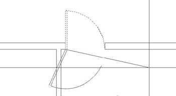
Figure 4.35: The mirror image moves as the mirror line rotates. - Hold the crosshair cursor directly to the right of the first point picked, along the inside wall line. The mirror image appears where you want the door.
- Activate the Endpoint Osnap again and pick the lower end of the right jamb line. The mirror image disappears, and the prompt changes to read Delete source objects? [Yes/No] <N>:. You have two choices. You can keep both doors by pressing and accepting the default (No). Or you can discard the original one by typing y (for yes) in the command line and pressing .
- Type y. The flipped door is displayed, and the original one is deleted (see Figure 4.36). The Mirror command ends. Like the Copy command, the Mirror command ends automatically after one mirroring operation.
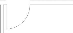
Figure 4.36: The mirrored door and swing
It may take some practice to become proficient at visualizing and designating the mirror line, but once you are used to it, you will have learned a very powerful tool. Because many objects—including building layouts, widgets, steel beams, road cross sections, and so on—have some symmetry to them, wise use of the Mirror command can save you a lot of drawing time.
You have two more swinging doors to place in the floor plan.
Finishing the Swinging Doors
You can’t copy the existing doors and swings to the interior openings because the sizes don’t conform, but you can use the same procedure to draw one door and swing and then copy it to the other opening.
| Note |
We could have used the Stretch command to lengthen the door, but that’s an advanced Modify command and won’t be introduced until Chapter 9. Besides, the arc would have to be modified to a larger radius. It’s easier to just draw another door and swing to a different size. |
- Click the Zoom Previous button on the Standard toolbar. Then click the Zoom Window button right next to the Zoom Previous button, and make a zoom window to magnify the view of the interior door openings. Be sure to make the zoom window large enough to leave some room for the new doors to be drawn (see Figure 4.37).
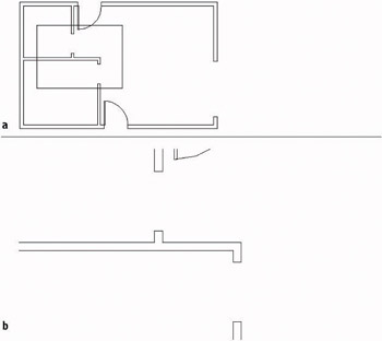
Figure 4.37: A zoom window in the interior door opening area (a), and the results of the zoom (b) - Follow the same procedure to draw the door and swing in the lower opening. Here is a summary of the steps:
- Use the Rectangle command and Endpoint Osnap to draw the door from the hinge point to a point @1.5,-2'6.
- Rotate the door around the hinge point to an open position. You will have to use a rotation angle of –90.
- Use the Start, Center, Angle option of the Arc command to draw the door swing, starting at the upper-left corner of the door and using Endpoint Osnap for the two picks.
The Start, Center, Angle options, as well as a few others, of the Arc command require that you choose the start point for the arc in such a way that the arc is drawn in a counterclockwise direction. If you progress in a clockwise direction, use a negative number for the angle.
- Use the Copy command to copy this door and swing to the other interior opening. The base point will be the hinge point, and the second point will be the left end of the lower jamb line in the upper opening. Use the Endpoint Osnap for both picks.
- Use the Mirror command to flip up this copy of the door and swing. The mirror line will be different from the one used for the back door. The geometrical arrangement at the back opening required that the door and its swing be flipped across the opening. For this one, the door and its swing must flip in a direction parallel to the opening. For this opening, the mirror line is the lower jamb line itself, so pick each end of this line (using Endpoint Osnap) to establish the mirror line.
- Use the Zoom Previous button to see the four swinging doors in place (see Figure 4.38).
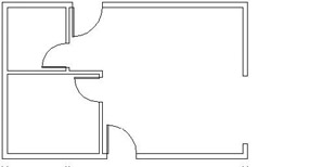
Figure 4.38: The four swinging doors in place
The last door to draw is the sliding glass door. This kind of door requires an entirely different strategy, but you’ll use commands familiar to you by now.
| Note |
The buttons you have been clicking in this chapter are also referred to as icons and tools. When they are in dialog boxes or on the status bar, they actually look like buttons to push that have icons on them. When they are on the toolbars, they look like icons, that is, little pictures. But when you move the Pointer Arrow cursor onto one, it takes on the appearance of a button with an icon on it. All three terms—button, icon, and tool—will be used interchangeably in this book. |
Drawing a Sliding Glass Door
Sliding glass doors are usually drawn to show their glass panels within the door frames.

To draw the sliding door, you will apply the Line, Offset, and Trim commands to the 7' opening you made earlier. It’s a complicated exercise but it will teach you a lot about the power of using these three commands in combination.
- Click the Zoom Window button on the Standard toolbar, and make a zoom window closely around the 7' opening. In making the zoom window, pick one point just above and to the left of the upper doorjamb and below and to the right of the lower jamb. This will make the opening as large as possible while including everything you will need in the view (see Figure 4.39).
Figure 4.39: The view when zoomed in as closely as possible to the 7' opening - You will be using several Osnaps for this procedure, so it will be convenient to have the Osnap Flyout toolbar more immediately available. Here’s how:
- Right-click any button on any of the toolbars on your screen to open the Toolbar menu.
- Click Object Snap. The Toolbar menu closes, and the Object Snap toolbar is displayed in the drawing area. It is in floating mode.
- Put the cursor on the colored title bar of the Object Snap toolbar, and holding down the left mouse button, drag the toolbar to the right side of the drawing area. Dock it there by releasing the mouse button (see Figure 4.40). Now you can easily select all Object Snaps as needed.
Figure 4.40: The Object Snap toolbar docked to the right of the drawing area
- Offset each jamb line 2" into the doorway opening (see Figure 4.41).
Figure 4.41: Jamb lines offset 2" into the doorway opening - Type L to start the Line command. Click the Midpoint Osnap button on the Object Snap toolbar, and then place the cursor near the midpoint of the upper doorjamb line. Notice that a colored triangle appears when your cursor is in the vicinity of the midpoint. A symbol with a distinctive shape is associated with each Osnap. When the triangle appears at the midpoint of the jamb line, left-click. Click the Midpoint Osnap button again, move the cursor to the bottom jamb line, and, when the triangle appears at that midpoint, click again. Press to end the Line command.
- Start the Offset command and type 1.5 to set the offset distance. Pick the newly drawn line, and then pick a point anywhere to the right side. Then, while the Offset command is still running, pick the original line again, and pick another point in a blank area somewhere to the left side of the doorway opening (see Figure 4.42). Press to end the Offset command.
A line offset from itself, that is, a copy of the selected line, is automatically made at a specified perpendicular distance from the selected line.
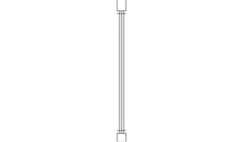
Figure 4.42: The offset vertical line between the jambs - Check the status bar to see if Ortho is on. If it’s not, click it to activate it. Type L to start the Line command. Click the Midpoint Osnap button, and then move the cursor near the midpoint of the left vertical line. When the colored triangle appears at the midpoint of this leftmost line, click. Hold the cursor out directly to the right of the point you just selected to draw a horizontal line through the three vertical lines. When the cursor is about two feet to the right of the three vertical lines, pick a point to set the endpoint of this guideline. Press to end the Line command (see Figure 4.43).
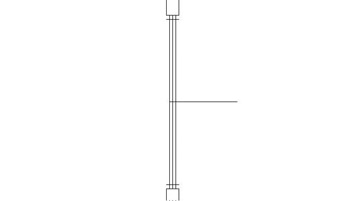
Figure 4.43: The horizontal guideline drawn through vertical lines - Type o to start the Offset command. Type 1 to set the offset distance. Select this new line, and then pick a point in a blank area anywhere above the line. Pick the new horizontal line again, and then pick anywhere below it. The new line has been offset 1" above and below itself (see Figure 4.44). Now you have placed all the lines necessary to create the sliding glass door frames in the opening. You still need to trim back some of these lines and erase others. Press to end the Offset command.
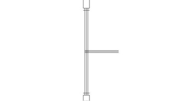
Figure 4.44: The offset horizontal guideline - Start the Trim command by typing tr. When you are prompted to select cutting edges, pick the two horizontal lines that were just created with the Offset command. Then press .
- Now trim the two outside vertical lines by selecting them as shown in Figure 4.45a. The result is shown in Figure 4.45b.
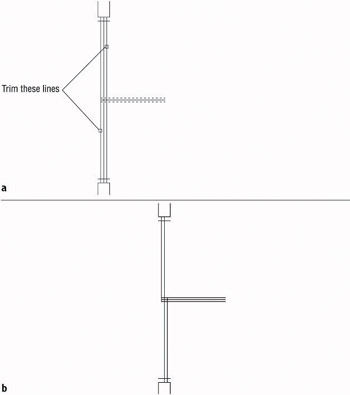
Figure 4.45: Picking the vertical lines to trim (a), and the result (b) - Press twice to stop and restart the Trim command. When you are prompted to select cutting edges, use a special window called a crossing window to select all the lines visible in the drawing. A crossing window will select everything within the window or crossing it. Here’s how to do it:
- Pick a point above and to the right of the opening.
- Move the cursor to a point below and to the left of the opening, forming a window with dashed lines (see Figure 4.46).
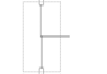
Figure 4.46: The crossing window for selecting cutting edges - Pick that point. Everything inside the rectangle or crossing an edge of it is selected.
- Press .
- To trim the lines, pick them at the points noted in Figure 4.47a. When you finish trimming, the opening should look like Figure 4.47b. Be sure to press to end the Trim command.
Note If all lines don’t trim the way you expect them to, you may have to change the setting for the Edgemode system variable. Cancel the trim operation and undo any trims you’ve made to the sliding glass door. Type edgemode, and then type 0. Now start the Trim command and continue trimming.
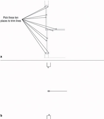
Figure 4.47: Lines to trim (a), and the result (b) - Start the Erase command and erase the remaining horizontal guideline.
To finish the sliding glass doors, you need to draw in two lines to represent the glass panes for each door panel. Each pane of glass is centered inside its frame, so the line representing the pane will run between the midpoints of the inside edge of each frame section.
- Type L to start the Line command, and pick the Midpoint button on the Object Snap toolbar.
- For each of the two sliding door frames, put the cursor near the midpoint of the inside line of the frame section nearest the jamb. When the colored triangle appears there, click.
Then select the Perpendicular Osnap button from the Object Snap toolbar and move the cursor to the other frame section of that door panel. When you get near the horizontal line that represents both the inside edge of one frame section and the back edge of the frame section next to it, the colored Perpendicular Osnap symbol will appear on that line. When it does, select that point.
- Press to end the Line command.
- Press to restart the Line command, and repeat the procedure described in step 14 for the other door panel, being sure to start the line at the frame section nearest the other jamb. The finished opening should look like Figure 4.48a.
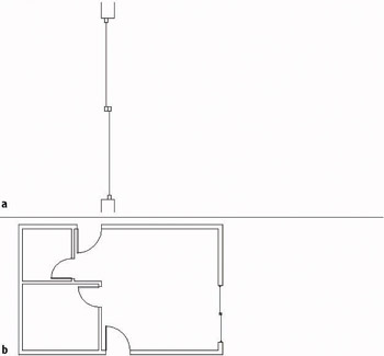
Figure 4.48: The finished sliding glass doors (a), and the floor plan with all doors finished (b) - Use the Zoom Previous button to see the full floor plan with all doors (see Figure 4.48b).
- Save this drawing as Cabin04c.
This completes the doors for the floor plan. The focus here has been on walls and doors and the strategies for drawing them. As a result, you now have a basic floor plan for the cabin, and you will continue to develop this plan in the next chapter.
The overall drawing strategy that has been emphasized in this chapter is using objects already in the drawing to create new ones. You started with four lines that constituted the outside wall lines. By offsetting, filleting, extending, and trimming, you drew all the walls and openings without drawing any new lines. For the swinging doors, you made two rectangles and two arcs. Then by copying, rotating, and mirroring, you formed the other two swinging doors. For the sliding glass door, you drew two new lines; then you used Offset, Trim, and Erase to finish the door. So you used four lines and created six new objects to complete the walls and doors. This is a good start in learning to use AutoCAD wisely.
Throughout this chapter, I have indicated several instances when you can press the spacebar instead of the key. This can be handy if you keep one hand resting on the keyboard while the other hand controls the mouse. For brevity, I will continue to instruct you to use and not mention the spacebar, but as you get better at drawing in AutoCAD, you may find the spacebar a useful substitute for in many cases. You will find your preference. You can substitute the spacebar for when handling the following tasks:
- Restarting the previous command
- Ending a command
- Moving from one step in a command to the next step
- Entering a new offset distance or accepting the current offset distance
- Entering relative or absolute coordinates
- Entering an angle of rotation
Note When you used the Rectangle command to draw the swinging doors, you had to use relative Cartesian coordinates because relative polar coordinates would have required you to know the diagonal distance across the plan of the door and the angle of that distance as well.
By working with the tools and strategies in this chapter, you now should have an idea of an approach to drawing many objects. In the next chapter, you will continue in the same vein, learning a few new commands and strategies as you add steps, a balcony, a kitchen, and a bathroom to the floor plan.
If You Would Like More Practice
If you would like to practice the skills you have learned so far, here are some extra exercises.
An Alternate Sliding Glass Door
Here is a simplified version of the sliding glass door of the cabin. It doesn’t include any representation of the panes of glass and their frames.
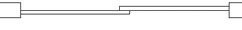
To draw it, use a technique similar to the one described in the previous section. Copy the jambs for the 7' opening to the right, and draw this door between them.
An Addition to the Cabin
This addition is connected to the cabin by a sidewalk and consists of a remodeled two-car garage in which one car slot has been converted into a storage area and an office (see Figure 4.49). Use the same commands and strategies you have been using up to now to draw this layout adjacent to the cabin. Save this exercise as Cabin04c-addon.dwg.
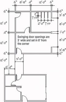
Figure 4.49: The garage addition
Refer to this chapter and the previous one for specific commands. Here is the general procedure:
- Draw the two lines that represent the walkway between the two buildings.
- Draw the outside exterior wall line.
- Use Offset, Fillet, and Trim to create the rest of the walls and wall lines.
- Use Offset, Extend, and Trim to create the openings.
- Use Rectangle and Arc to create a swinging door.
- Use Copy, Rotate, and Mirror to put in the rest of the doors.
- Use Offset, Line, and Copy to draw the storage partitions.
Draw Three Views of a Block
Use the tools you have learned in the last few chapters to draw the top, right side, and front views of the block shown in Figure 4.50.
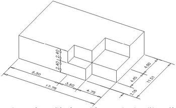
Figure 4.50: The block
Below is a graphic representation of the twelve steps necessary to complete the exercise.
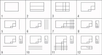
Here are the 12 steps in summary that correspond to the 12 drawings. Start with the top view:
- Start a new drawing. Leave all settings at the defaults. Use relative polar or relative Cartesian coordinates and the Line command to draw a rectangle 17.75 wide and 11.51 high.
- Offset the bottom horizontal line up 2.16 and the new line up 4.45.
- Offset the right vertical line 4.75 to the left and the new line 3.50 to the left.
- Use the Trim command to trim back lines and complete the view.
Next, do the right side view:
- Draw a vertical line to the right of the top view. Make it longer than the top view is deep.
- Offset the vertical line 2.4 to the right, and then offset the new line 2.4 to the right also.
- Use Endpoint Osnap to draw lines from the corner points of the top view across the three vertical lines.
- Trim the lines back to complete the side view.
Finally, draw the front view:
- Draw a horizontal line below the top view. Make it longer than the top view is wide.
- Offset this line 2.4 down, and then offset the new line 2.4 down.
- Use Endpoint Osnap to draw lines from the corner points of the top view, down across the three horizontal lines.
- Trim the lines back to complete the view.
This ends the exercise. There are ways to rotate and move each view relative to the other views. We will look at those commands later in the book, and draw more views in Chapter 8.
Are You Experienced?
Now you can
- offset exterior walls to make interior walls
- zoom in on an area with the Zoom Window command and zoom back out with the Zoom Previous command
- use the Rectangle and Arc commands to make a door
- use the Endpoint, Midpoint, and Perpendicular Object Snap modes
- use the Crossing Window selection tool
- use the Copy and Mirror commands to place an existing door and swing in another opening
- use the Offset and Trim commands to make a sliding glass door
Introduction
- Getting to Know AutoCAD
- Basic Commands to Get Started
- Setting Up a Drawing
- Gaining Drawing Strategies: Part 1
- Gaining Drawing Strategies: Part 2
- Using Layers to Organize Your Drawing
- Grouping Objects into Blocks
- Generating Elevations
- Working with Hatches and Fills
- Controlling Text in a Drawing
- Dimensioning a Drawing
- Managing External References
- Using Layouts to Set Up a Print
- Printing an AutoCAD Drawing
- Appendix A Look at Drawing in 3D
EAN: N/A
Pages: 159
- Structures, Processes and Relational Mechanisms for IT Governance
- An Emerging Strategy for E-Business IT Governance
- Technical Issues Related to IT Governance Tactics: Product Metrics, Measurements and Process Control
- Governance in IT Outsourcing Partnerships
- Governance Structures for IT in the Health Care Industry
