Generating Elevations
GeneratingElevations
Overview
- Drawing an exterior elevation from a floor plan
- Using grips to copy objects
- Setting up, naming, and saving a User Coordinate System and a new view
- Transferring height lines from one elevation to another
- Moving and rotating elevations
Now that you have created all the building components that will be in the floor plan, it’s a good time to draw the exterior elevations. Elevations are horizontal views of the building, seen as if you were standing facing the building instead of looking down at it, as you do in the floor plan. An elevation view shows you how windows and doors fit into the walls and gives you an idea of how the building will look from the outside. In most architectural design projects, the drawings include at least four exterior elevations: front, back, and one from each side.
I’ll go over how to create the front elevation first. Then I’ll discuss some of the considerations necessary to complete the other elevations, and you’ll have an opportunity to draw these on your own. Finally, we will look at how interior elevations are set up. They are similar to exterior elevations, but are usually of individual walls on the inside of a building to show how objects, such as doors, windows, cabinets, shelves, and finishes, will be placed on the walls.
In mechanical drawing, the item being drawn is often a machine part, or a gadget. The drafter uses orthographic projection to illustrate various views of the object and call them—instead of elevations and plans—front view, top view, side view, and so on. An exercise at the end of this chapter will give you practice with orthographic projection, but the procedure will be the same, whether you are drawing buildings or mechanical objects.
Orthographic projection is a method for illustrating an object in views set at right angles to each other—hence, front, top, side, back, and so on.
Drawing the Front Elevation
You draw the front elevation using techniques similar to those used on a traditional drafting board. You will draw the front elevation view of the cabin directly below the floor plan by dropping lines down from key points on the floor plan and intersecting them with horizontal lines representing the heights of the corresponding components in the elevation. Those heights are shown in Figure 8.1.
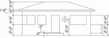
Figure 8.1: The front elevation with heights of components
- Open Cabin07b.
- Create a new layer called F-elev. Assign it color 42 and make it current. Here’s a summary of the steps to do this:
- Click the Layer Properties Manager button, and then click New.
- Type F-elev and press .
- Click the colored square for the F-elev layer. Type 42.
- Click the Set Current icon, and then click OK.
- Use the Layer Control drop-down list to thaw the Roof and Headers layers. (They were frozen at the beginning of Chapter 7. We want the roof and headers to be visible again.) Then offset the bottom horizontal roofline 24' down. The offset line will be off the screen.
Objects on layers that are “frozen” are invisible. To make them visible again “thaw” their layers by clicking the layers’ darkened sun icons on the Layer Control drop-down list.
- Click the Zoom Extents button on the Zoom flyout toolbar.
- Use Realtime Zoom to zoom out just enough to bring the offset roofline up off the bottom edge of the drawing area.
- Erase this offset line. Your drawing should look like Figure 8.2.
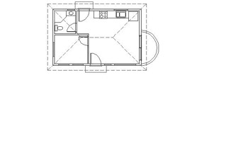
Figure 8.2: The floor plan with space below it for the front elevation
Setting Up Lines for the Heights
You need to establish a base line to represent the ground. Then you can offset the other height lines from the base line or from other height lines.
- Check the status bar to make sure that Polar, Osnap, and Model are in the on position while the other buttons are off. Draw a horizontal ground line across the bottom of the screen using the Line command. Make sure the line extends on the left to a few feet beyond a point directly below the outside edge of the roof, and on the right to a few feet beyond a point directly below the right edge of the balcony (see Figure 8.3).
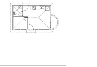
Figure 8.3: The floor plan with the ground line - Offset the ground line 10" up to mark the height of the step. Then offset this new line 2" up to mark the top of the threshold.
- Move back to the ground line and offset it 4' up to mark the top of the balcony wall and the bottom of the windows.
- Offset the bottom line for the windows 3'-6" up to mark the top of the door and windows.
- Offset the top line for the windows and door 1'-6" up to mark the soffit of the roof.
A soffit is the underside of the roof overhang that extends from the outside edge of the roof back to the wall.
- Offset the soffit line 6" up to mark the lower edge of the roof’s top surface.
- Offset this lower edge of the roof’s top surface 3' up to mark the roof’s ridge (see Figure 8.4).
- Press to end the Offset command.
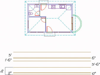
Figure 8.4: The horizontal height lines for the elevation in place
Each of these lines represents the height of one or more components of the cabin. Now you will drop lines down from the points in the floor plan that coincide with components that will be visible in the front elevation. The front elevation will consist of the balcony, front step, front door and windows, the front corners of the exterior walls, and parts of the roof.
Using Grips to Copy Lines
In the following steps, you will use grips to copy the dropped lines.
- Start a line from the lower-left corner of the walls of the building. Select Perpendicular Osnap and click the ground line. Press to end the Line command (see Figure 8.5a).
- At the Command: prompt, select the line you just drew. Small squares appear on the line’s midpoint and endpoints (see Figure 8.5b). These are grips.
- Click the grip on the upper endpoint. The grip changes color, and the prompt changes to Specify stretch point or [Base point/Copy/ Undo/eXit]:. This is the Stretch command, which is activated by grips. Any time you activate a grip, the Stretch command automatically starts.
The Stretch command is a modifying tool that you use to lengthen or shorten lines and other objects. You’ll have a chance to use it in Chapter 9.
- Right-click, and choose Move from the shortcut menu. Right-click again, and choose Copy from the shortcut menu. This selects the Copy option. You’ll use the Move command with its Copy option to copy the line that you just selected.
Each of the commands that work with grips has a Copy option, which keeps the original object as is while you modify the copy.You can copy with grips in several ways that are not possible with the regular Copy command.
- Select the lower-right corner of the building. The line is copied to this corner.
- Select the Quadrant Osnap, and click the right extremity of the outside wall line of the balcony. Another line is copied, this time to the balcony. It does not extend to the ground line because it was directly copied and therefore is the same length as the other two lines. You will extend it later.
- Type x to end the Move command. Press Esc to remove the grips. Your drawing will resemble Figure 8.5c.
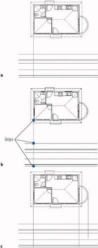
Figure 8.5: Dropping a line from the floor plan to the elevation (a), the dropped line with grips (b), and the copied lines (c)
Getting a Grip on Grips
In Chapter 7, you saw how to use grips to detect whether an object is a block. They actually serve a larger function. The grips feature is a tool for editing objects quickly, using one or more of the following five commands: Stretch, Move, Rotate, Scale, or Mirror. These commands operate a little differently when using grips than when using them normally.
The commands can also do a few more things with the help of grips. Each command has a Copy option. So, for example, if you rotate an object with grips, you can keep the original object unchanged while you make multiple copies of the object in various angles of rotation. You can’t do this by using the Rotate command in the normal way or by using the regular Copy command.
To use grips, follow these steps:
- When no commands have been started, click an object that you want to modify.
- Click the grip that will be the base point for the command’s execution.
- Right-click at this point and choose any of the five commands from the shortcut menu that opens on the drawing area. (You can also cycle through the five commands by pressing the spacebar and watching the command prompt.)
- When you see the command you need, execute the necessary option.
- Type x when finished.
- Press Esc to remove the grips.
The key to being able to use grips efficiently is knowing which grip to select to start the process. This requires a good understanding of the five commands that work with grips.
This book does not cover grips in depth, but will introduce you to the basics. You will get a chance to use the Move command with grips in this chapter, and we will use grips again when we get to Chapter 11.
Keep the following in mind when working with grips:
- Each of the five commands available for use with grips requires a base point. For Mirror, the base point is the first point of the mirror line. By default, the base point is the grip that you select to activate the process, but you can change base points. After selecting a grip, type b and pick a different point to serve as a base point; then continue the command.
- When you use the Copy option with the Move command, you are essentially using the regular Copy command with the Multiple option.
Trimming Lines in the Elevation
The next task is to trim the appropriate lines in the elevation, but first you need to extend the line dropped from the balcony down to the ground line.
- Click the line dropped from the balcony. Grips appear on the line. Click the bottom grip. Select Perpendicular Osnap, and then place the cursor on the ground line. When the perpendicular symbol appears on the ground line, click. Then press Esc to remove the grips.
- Start the Trim command. Select the soffit line for a cutting edge for the two building lines, and then press . The two lines to be trimmed are the ones that were dropped from the corners of the building. Pick them anywhere between the soffit line and the floor plan. The lines are trimmed (see Figure 8.6).
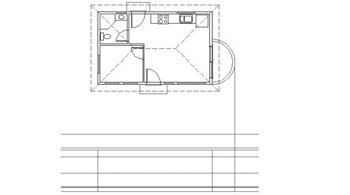
Figure 8.6: The building corner lines after being trimmed to the soffit line - Press twice to stop and restart the Trim command. You need to trim a horizontal height line and a vertical dropped line for the balcony. To select cutting edges, pick the line dropped from the balcony and the horizontal height line that represents the top of the balcony wall and the bottom of the windows (see Figure 8.7a). Press .
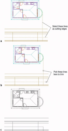
Figure 8.7: Trimming the balcony lines: selecting cutting edges (a), picking lines to be trimmed (b), and the result (c) - To trim the lines properly, click the line dropped from the balcony anywhere above the balcony in the elevation. To trim the horizontal line representing the top of the balcony wall, pick this line anywhere to the right of the line dropped from the balcony (see Figure 8.7b). The lines are trimmed (see Figure 8.7c). Press to end the Trim command.
This is the basic process for generating an elevation: Drop lines down from the floor plan, and trim the lines that need to be trimmed. The trick is to learn to see the picture you want somewhere in all the crossed lines and then to be able to use the Trim command accurately to cut the appropriate lines away.
Tips for Using the Trim and Extend Commands
Trim and Extend are sister commands. Here are a few tips on how they work:
Basic OperationBoth commands involve two steps: selecting cutting edges (Trim) or boundary edges (Extend), and selecting the lines to be trimmed or extended. Select the cutting or boundary edges first, and then press .Then pick lines to trim or extend. Press to end the commands.
Trimming and Extending in the Same CommandIf you find that a cutting edge for trimming can also serve as a boundary edge, hold down the Shift key and click a line to extend it to the cutting edge. The opposite is true for the Extend command.
Correcting ErrorsIt’s easy to make a mistake in selecting cutting or boundary edges or in trimming and extending. You can correct a mistake in two ways:
- If you select the wrong cutting or boundary edge, type r, and then rechoose the lines that were picked in error. They will unghost. If you need to keep selecting cutting or boundary edges, type a and select new lines. When finished, press to move to the second part of the command.
- If you trim or extend a line incorrectly, click the Undo button on the Standard toolbar. This will undo the last trim. Click Undo again if you need to untrim or unextend more lines. When you have made all corrections, continue trimming or extending. Press to end the command.
If the command ended and you click the Undo button, all trimming or extending that was done in the last command will be undone.
Drawing the Roof in Elevation
To draw the roof in elevation, follow these steps:
- Use the Line command to start a line from the right endpoint of the ridgeline of the roof. Then click the Snap To None Osnap button on the Object Snap toolbar. Draw the line straight down past the soffit line (see Figure 8.8a). End the Line command.
If the Osnaps that you have running get in the way of your trying to pick a point near to but not on an object, click the Snap To None Osnap. This will turn off any running Osnaps for the next pick. After that pick, the running Osnaps are reactivated.
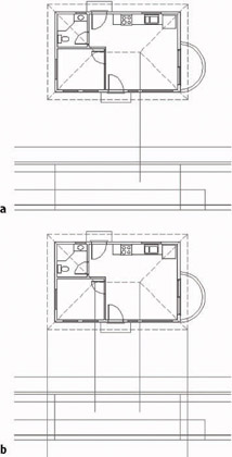
Figure 8.8: Dropping a line from the roof (a), and copying this line (b) - Click this line to activate grips. Select the grip at its upper endpoint. Press the spacebar once to access the Move command.
- Type c, and then click the lower-right and lower-left corners of the roof and the left endpoint of the ridgeline. This copies the dropped line to these three locations (see Figure 8.8b).
Note If you have difficulty picking the left end of the ridgeline, hold the cursor on the lower-left hip line, just above the midpoint. That should produce an Endpoint symbol where you want it.
- Type x to end the Move command, and then press Esc to remove the grips.
- Start the Trim command, and select the two lines dropped from the ridgeline. Press .
- In the elevation, pick the ridgeline to the left and right of these dropped lines (see Figure 8.9a). The ridgeline is trimmed back to its correct length (see Figure 8.9b). Press .
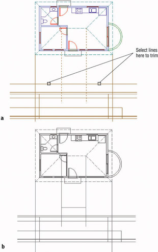
Figure 8.9: Selecting the lines to trim (a), and the result (b) - Erase the two dropped lines that were just used as cutting edges.
- Restart the Trim command. Select the two lines dropped from the corners of the roof, the horizontal soffit line, and the line 6" above the soffit line to be cutting edges—four lines in all. Press .
- To do the trim, click the dropped lines above and below the two horizontal cutting edges; then click the two selected horizontal lines to the left and right of the dropped lines—eight picks in all (see Figure 8.10a). Press . The roof edge is complete (see Figure 8.10b).
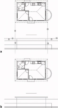
Figure 8.10: Trimming the lines to form the roof edge (a), and the result (b) - Use the Line command to draw the two hip lines from the roof edge to the ridgeline. Zoom in to do this if you need to; then Zoom Previous when you’re finished to view the completed front elevation of the roof (see Figure 8.11).
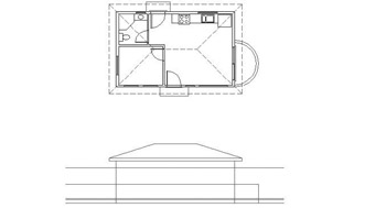
Figure 8.11: The completed roof in elevation
Putting in the Door, the Step, and the Windows
To finish the front elevation, all we need to put in are the front door, the windows, the front step, and the threshold and a few finishing touches. We’ll do the door and all the windows, except the round one, in one cycle. We’ll save the step and threshold for later.
- Use Zoom Window to zoom in to as close a view as possible that still displays as much of the drawing as you need. You will need to see the entire elevation, the front wall of the floor plan, and the lower half of the balcony, so make your zoom window large enough to enclose just those elements (see Figure 8.12a). I call this process strategic zooming.
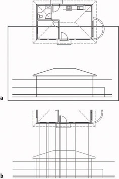
Figure 8.12: The window for zooming in closer (a), and dropping a line from a window and copying it to the edges of the windows and the front door (b) - Draw a line from the left end of the leftmost window in the front wall of the floor plan to the ground line, using Perpendicular Osnap for the second point. End the Line command.
- Click the line to display its grips, and then click the upper grip on this line at the Command: prompt to activate it. Follow the same process as you did in steps 2 and 3 of the “Drawing the Roof in Elevation” section to copy this line to the following:
- Each endpoint of the jamb line of each window in the front wall, except the 2' circular one to the right of the front door
- Each edge of the front door opening
Watch your Endpoint Osnap symbol carefully.
You can’t zoom or pan while using grips. If you need to adjust your view, do so before displaying them.
- Type x to end the Move command. Press Esc to remove the grips (see Figure 8.12b).
Before we begin trimming all these lines, study the floor plan and elevation for a minute, and try to visualize the three windows and the door in the middle of all the crossing lines. We’ll trim a few at a time, working from the top down.
- Start the Trim command. For cutting edges, select the horizontal line representing the top of the windows and doors, and select the eight lines you just dropped from the floor plan. Press .
- To trim, pick the horizontal line at each segment between the windows and the door and near the endpoints of the line (five places). Then pick each selected dropped line above the tops of the windows and door (eight places). This makes 13 places to pick. Then press . The results of the trim are shown in Figure 8.13.
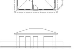
Figure 8.13: Trimming the top of the door and windowsMoving down, trim the lines that form the bottom of the windows.
- Start the Trim command. Select the following as cutting edges:
- The horizontal line representing the bottom of the window and the top of the balcony wall
- The six vertical lines forming the sides of the windows
- The vertical line representing the right edge of the front wall
Press .
- To trim, pick the horizontal line at the following places:
- At each segment between the windows (two picks)
- Between the right edge of the 6' window and the right edge of the building (one pick)
- Where it extends to the left of the leftmost window (one pick)
Then pick the vertical lines that extend below the bottoms of the windows (six picks). This will be a total of 10 picks. Then press . The results of the trim are shown in Figure 8.14.
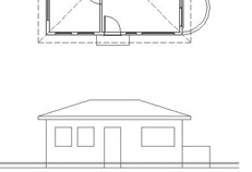
Figure 8.14: Trimming the bottom of the windows
| Note |
It will be helpful if you zoom in to a closer view of the front elevation when you are picking lines to trim. After step 8, Zoom Previous. |
Now we will draw the step and threshold, the bottom of the door, and the balcony floor.
- Drop a line down from the left corner of the threshold to a point past the ground line. Use grips to copy this line to the other corner of the threshold and to the two corners of the step. End the grips (see Figure 8.15a).
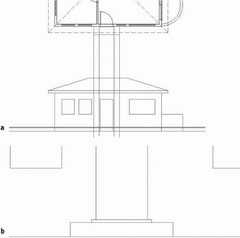
Figure 8.15: Dropped and copied lines for the step and threshold (a), and the finished step and threshold (b) - Zoom in to a close view of the step and threshold. Use the Trim command to trim away the lines so that the result looks like Figure 8.15b. You’ll probably have to stop and restart the command a couple of times in order to make all the trims you need. Here’s one way to do it, in summary form:
- Create the step first. For cutting edges, select the two lower horizontal lines and the two outer vertical lines. To trim, pick each of these lines (except the ground line) in two places above and below or to the left and right of the step (6 picks).
- Create the threshold. For cutting edges, select the four lines that form the outside edges of the threshold. To trim, pick each of these lines (except the line that forms the top of the step) in two places above and below or to the left and right of the threshold (6 picks).
- Trim the left and right edges of the door up to the top of the threshold (see Figure 8.15b).
- When finished, Zoom Previous to a view of the front elevation and the bottom of the floor plan.
The results show a nearly complete front elevation. To finish it, you need to put in the round window and complete the balcony. We’ll then add some final touches. Take another look at Figure 8.1 (shown earlier), and note that the center of the round window is 6' above the ground line.
- Offset the ground line 6' up.
- Start the Line command; then click the Snap To Insert button on the Object Snap toolbar. Click the 2' window in the floor plan to start a line at the insertion point of this block reference. Draw the line down through the newly offset line. Then draw a circle, using the intersection of these two lines as the center, and give it a 12" radius.
- Start the Trim command and select the circle as a cutting edge; then press .
- Pick the intersecting lines passing through the circle in four places outside the circle. The round window is finished (see Figure 8.16).
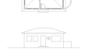
Figure 8.16: The completed round window - Make a zoom window around only the front elevation.
- Offset the vertical line representing the balcony’s right edge 6" to the left. Then offset the ground line up 10". These lines will serve to indicate the balcony’s floor and inside wall.
- Fillet these two lines at their intersection with a radius of zero. Then trim the balcony floor line back to the right wall line of the cabin.
- Select these two new lines. Click the Properties button to open the Properties palette.
- Click Linetype. Then open the Linetype list and click Dashed. Close the Properties palette and press the Esc key. The lines are changed to dashed lines to indicate that they are hidden in the elevation (see Figure 8.17).
This is a rare case in which we are assigning a line type to an object rather than to a layer. See the discussion at the end of this chapter.
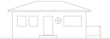
Figure 8.17: The completed balcony - Zoom Previous twice to a view of the completed front elevation with the entire floor plan. Save this drawing as Cabin08a.
Finishing Touches
You have gleaned all the information you can from the floor plan to help you with the front elevation. You might, however, want to add some detail to enhance the appearance of the elevation.
- Try zooming in and adding detail to the windows and door, and place an extra step leading to the front step. Figure 8.18 shows an example. Yours can be different.
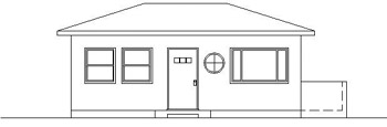
Figure 8.18: The front elevation with detail added - Zoom Previous to a full view of your drawing when finished.
- Save this drawing as Cabin08b.
Generating the Other Elevations
A full set of drawings to be used by contractors to construct a building will include an elevation for each side of the building. In traditional drafting, the elevations are usually drawn on separate sheets. This requires transferring measurements from one drawing to another by taping drawings next to each other, turning the floor plan around to orient it to each elevation, and several other cumbersome techniques. You do about the same thing on the computer, but it is much easier to move the drawing around. You will be more accurate, and you can quickly borrow parts from one elevation to use in another.
Making the Rear Elevation
Because the rear elevation shares components and sizes with the front elevation, you can mirror the front elevation to the rear of the building and then make the necessary changes.
- Open Cabin08a. You need to change the view to include space above the floor plan for the rear elevation.
- Use Realtime Pan to move the floor plan to the middle of the screen. Then use Realtime Zoom to zoom out the view enough to include the front elevation.
- Start the Mirror command. Use a window to select the front elevation and press .
- For the mirror line, select the Midpoint Osnap and pick the right edge line of the roof in the floor plan.
- With Polar Tracking on, hold the crosshair cursor directly to the right of the point you just picked (see Figure 8.19a) and pick another point. At the Delete source objects?[Yes/No]<N> prompt, press to accept the default of No. The front elevation is mirrored to the rear of the cabin (see Figure 8.19b).
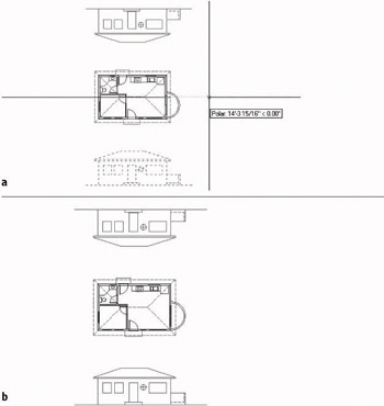
Figure 8.19: Specifying a mirror line (a), and the result (b)You can now make the necessary changes to the rear elevation so that it correctly describes the rear of the cabin. But you might find it easier to work if the view is right side up.
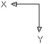
- Choose View Display UCS Icon On to display the User Coordinate System icon. (We turned it off in Chapter 5.) Take a look at the icon for a moment. The two arrows in the icon show the positive X and Y directions of the current user coordinate system, the World Coordinate System, which is the default system for all AutoCAD drawings. We’ll change the orientation of the icon to the drawing and then change the orientation of the drawing to the screen.
The User Coordinate System (UCS) defines the positive X and Y directions relative to your drawing. A drawing can have several UCSs but can use only one at a time. The World Coordinate System (WCS) is the default UCS for all new drawings and remains available in all drawings.
- If your UCS icon is in the lower-left corner of the screen, go to step 8. Otherwise, choose View Display UCS Icon Origin. This should move the icon to the lower-left corner of the screen.
When a check mark is next to Origin in the menu, the UCS icon sits at the origin (or the 0,0 point) of the drawing. When Origin is unchecked, the icon sits in the lower-left corner of the screen.
- Type ucs z 180. This will rotate the icon to an upside-down position. The square box disappears, meaning that you are no longer using the default World Coordinate System.
- Choose View 3D Views Plan View Current UCS. The entire drawing is rotated 180, and the mirrored front elevation, which will eventually be the back elevation, is now right side up. Note that the UCS icon is now oriented the way it used to be, but the square in the icon is still missing. This signals that the current UCS is no longer the World Coordinate System.
You used the UCS command to reorient the UCS icon relative to the drawing. You then used the Current option of the Plan command to reorient the drawing on the screen so that the positive X and Y directions of the current User Coordinate System are directed to the right and upward, respectively. This process is a little bit like turning your monitor upside down to get the correct orientation, but easier.
- Use Realtime Zoom to zoom out enough to bring the outermost lines of the drawing slightly in from the edge of the drawing area. Then right-click and choose Zoom Window from the shortcut menu.
Move the cursor above and to the left of the floor plan; then click and hold down the mouse button. Drag open a window that encloses the floor plan and mirrored elevation. Release the mouse button. Press Esc to end Realtime Zoom (see Figure 8.20). Now you can work on the rear elevation.
When you access Zoom Window from the Realtime Zoom shortcut menu, it behaves differently from the regular Zoom Window. It requires a click-and-drag technique.
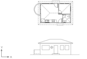
Figure 8.20: The cabin drawing rotated 180 and zoomed in
Revising the Rear Elevation
A brief inspection will tell us that the roof, balcony, and building wall lines need no changes. The windows and door need revisions, as do the step and threshold:
- The round window and one of the 3' windows need to be deleted.
- The two remaining windows need resizing and repositioning.
- The door, threshold, and step need repositioning.
- The step needs resizing.
These tasks can be accomplished quickly by using commands with which you are now familiar:
- Erase the round window and one of the 3' windows.
- Erase the sides of the remaining windows (see Figure 8.21a).
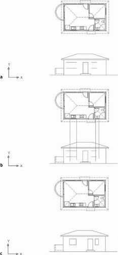
Figure 8.21: Erased lines (a), dropped lines (b), and the revised rear elevation (c) - Drop lines down from the jambs of the two windows in the back wall of the floor plan, past the bottoms of the windows in elevation (see Figure 8.21b).
- Extend the horizontal window lines that need to meet the dropped lines, and trim all lines that need to be trimmed. (You can use the Fillet command here instead of the Trim and Extend commands, but pick lines carefully.)
- Use a similar strategy to relocate and resize the step. You can move the door and threshold into position by using any of several procedures, including dropping a guideline or using the Temporary Tracking Point Osnap—or for LT users, using the Tracking tool—with Polar Tracking. Use Zoom Window and Zoom Previous as needed. The finished rear elevation looks like Figure 8.21c.
- You need to save the User Coordinate System (UCS) you used to work on this elevation so that you can quickly return to it in the future, from the World Coordinate System or from any other UCS you might be in. Type ucs s. For the UCS name, type rear_elev. This will allow you to recall it if you need to work on this elevation again.
You can save any UCS in this way. The World Coordinate System is a permanent part of all drawings, so it never needs to be saved.
- You can also save the view to be able to quickly recall it. Choose View Named Views to open the View dialog box. You can also start the View command by typing v.
- Click New to open the New View dialog box.
- In the New View text box, type rear_elev. Click the Current Display radio button and click OK. Back in the View dialog box, rear_elev appears in the list of views. Click OK again. Now you can restore the drawing to its original orientation with the front elevation below the floor plan and right side up.
You can name and save any view of your drawing and then restore it later.
- Type ucs to restore the World Coordinate System as the current coordinate system.
- Choose View 3D Views Plan View Current UCS. This zooms to Extents and displays a plan view of the drawing with the X and Y positive directions in their default orientation.
We created a new UCS as a tool to flip the drawing upside down without changing its orientation with respect to the World Coordinate System. You’ll get a chance to use UCSs in another way in the Appendix. But for now, we’ll use it again to create the right and left elevations.
Making the Left and Right Elevations
You can generate the left and right elevations using techniques similar to those you have been using for the front and back elevations. You need to be able to transfer the heights of building components from the front elevation to one of the side elevations. To do this, we’ll make a copy of the front elevation, rotate it 90, and then line it up so we can transfer the heights to the right elevation. It’s really quite easy.
- Use Realtime Zoom to zoom out slightly; then zoom in to a view of the floor plan and front elevation. Pan the drawing so that the floor plan and front elevation are on the left part of the drawing area. You need to transfer the height data from the front elevation to the right elevation. To ensure that the right elevation is the same distance from the floor plan as the front elevation, we’ll use a 45 line that extends down and to the right from the rightmost and lowermost lines in the floor plan.
- Turn on Polar Tracking, and be sure it’s set to 45. Also make sure that the Otrack button on the status bar is toggled on. Then set the Quadrant and Endpoint Osnaps to running, and be sure Midpoint Osnap is not running.
Steps 2 through 6 are for AutoCAD only. LT users should follow steps 2 through 6 in the following “Steps 2 through 6 for LT Users” sidebar.
- Start the Line command. Move the crosshair cursor to the right edge of the outside arc of the balcony in the floor plan. Hold it there for a moment. A cross will appear at the Quadrant point. Don’t click yet.
- Move the crosshair cursor to the lower-right corner of the step and hold it there until a cross appears at that point. Don’t click yet.
- Now move the crosshair cursor to a point directly to the right of the corner of the step and directly under the right quadrant point of the balcony (see Figure 8.22a). Vertical and horizontal tracking lines appear and intersect where the crosshair cursor is positioned, and a small x appears at the intersection. A tracking tool tip will also appear.
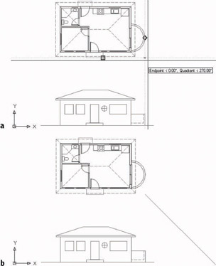
Figure 8.22: Starting a diagonal reference line with tracking points (a), and the completed diagonal line (b) - Click to start a line at this point.
Steps 2 through 6 for LT Users
LT users should follow these steps:
- Turn on Polar Tracking and be sure it’s set to 45.Then set the Quadrant and Endpoint Osnaps to be running, and make sure Midpoint Osnap is not running.
- Start the Line command, and then click the Tracking button on the Object Snap toolbar (it’s the top button).
- Move the cursor to the lower-right corner of the front step. When the Endpoint Osnap square appears there, click.
- Move the cursor to the right edge of the outer arc of the balcony. When the Quadrant Osnap diamond appears there, click.
- Press . A line is begun at a point just below and to the right of the floor plan, in line with the lower edge of the front step and the right extremity of the balcony.
Now continue with step 7.
- Move the crosshair cursor down, away from this point, and to the right at a negative 45 angle (or a positive 315 angle). When the 45 Polar tracking path appears, type 35'. Press again. The diagonal reference line is completed (see Figure 8.22b).
- Turn off Quadrant as a running Osnap.
- Start the Copy command, and select the entire front elevation and nothing else. Then press .
- For the base point, select the left endpoint of the ground line.
- For the second point, pick the Intersection Osnap and place the cursor on the diagonal line. When the x symbol with three dots appears, click. Then move the cursor to any point on the ground line of the front elevation. An x will appear on the diagonal line where the ground line would intersect it if it were longer (see Figure 8.23a).
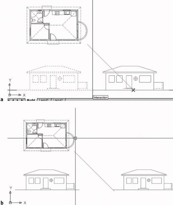
Figure 8.23: Making a copy of the front elevation (a) and adjusting the view (b) - When the x appears, click to locate the copy. Zoom out to include the copy; then Zoom Window to include the floor plan and front elevations (see Figure 8.23b).
- Start the Rotate command and select this copy of the front elevation; then press . Pick Intersection Osnap and click the intersection of the diagonal line with the ground line. For the angle of rotation, type 90 (see Figure 8.24a).
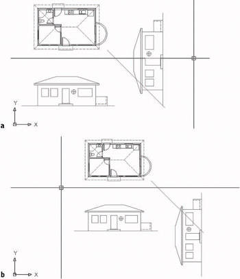
Figure 8.24: Rotating the copy of the front elevation (a) and the moved copy with the view adjusted - Start the Move command, and when prompted to select objects, type p. The rotated front elevation will be selected. For the base point, click a point in a blank space to the right of the upper endpoint of the ground line of the rotated elevation. For the second point, move the cursor down using Polar Tracking until the top of the ground line is lower than the bottom line of the front step in the plan view. Then click.
- Zoom out and Zoom Window to adjust the view (see Figure 8.24b).
Note If you’re working on a small monitor, you might have to do some extra zooming in and out that isn’t mentioned in these steps.
The rest of the process for creating the right elevation is straightforward and uses routines you have just learned. Here’s a summary of the steps:
- Set up a new UCS for the right elevation. (Type ucs z 90.) Use the Plan command to rotate the drawing to the current UCS.
- Drop lines from the floor plan across the height lines, which you will produce from the copied elevation.
- Trim these lines as required and add any necessary lines.
- Erase the copy of the front elevation and the diagonal transfer line.
- Name and save the UCS and view.
You can create the left elevation from a mirrored image of the right elevation. Here are the steps:
- Mirror the right elevation to the opposite side.
- Set up a UCS for the left elevation. Use Plan to rotate the drawing to the current UCS.
- Revise the elevation to match the left side of the cabin.
- Name and save the UCS and view.
When you have completed all elevations, follow these steps:
- Return to the World Coordinate System.
- Display the Plan view.
- Zoom out slightly for a full view of all elevations. The drawing will look like Figure 8.25a.
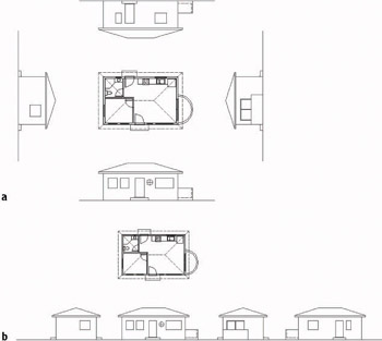
Figure 8.25: The finished elevations (a), and the elevations in line (b) - Save the drawing as Cabin08c.
Once an elevation is drawn, you can rotate it to the same orientation as the front elevation and move it to another area of the drawing. You can display the four elevations for the cabin next to each other, as shown in Figure 8.25b.
Drawing Scale Considerations
This last view raises several questions: How will these drawings best fit on a page? How many pages will it take to illustrate these drawings? What size sheet should be used? At what scale will the drawing be printed? In traditional hand drafting, the first line could not be drawn without answers to some of these questions. You have completed a great deal of the drawing on the computer without having to make decisions about scale and sheet size because in AutoCAD you draw in real-world scale or full-scale. This means that when you tell AutoCAD to draw a 10-foot line, it draws it 10 feet long. If you inquire how long the line is, AutoCAD will tell you that it is 10 feet long. Your current view of the line may be to a certain scale, but that changes every time you zoom in or out. The line is stored in the computer as 10 feet long.
You need to make decisions about scale when you are choosing the sheet size, putting text and dimensions on the drawing, or using hatch patterns and noncontinuous line types. Because we have a dashed line type in the drawing, we had to make a choice about scale in Chapter 6, when we assigned a linetype scale factor of 24 to the drawing. We chose that number because when the drawing consisted of only the floor plan and the view was zoomed as large as possible while still having all objects visible, the scale of the drawing was about 1⁄2" = 1'-0". That scale has a true ratio of 1:24, or a scale factor of 24. We will get further into scale factors and true ratios of scales in the next chapter.
If you look at your Cabin08c drawing with all elevations visible on the screen, the dashes in the dashed lines look like they might be too small, so you might need to increase the linetype scale factor. Don’t worry about that now. Beginning with the next chapter, and right on through the end of this book, we will need to make decisions about scale each step of the way.
Interior Elevations
You construct interior elevations using the techniques you learned for constructing exterior elevations. You drop lines from a floor plan through offset height lines and then trim them away. Interior elevations usually include fixtures and built-in cabinets and shelves, and they show finishes. Each elevation will consist of one wall and can include a side view of items on an adjacent wall if the item extends into the corner. Not all walls are shown in an elevation—usually only those that require special treatment or illustrate special building components. You might use one elevation to show a wall that has a window and to describe how the window is treated or finished and then assume that all other windows in the building will be treated in the same way unless noted otherwise. A few examples of interior wall elevations are shown in Figure 8.26. Try to identify which walls of the cabin each one represents.
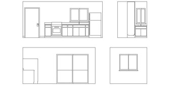
Figure 8.26: Samples of interior elevations of the cabin
In the next chapter, you will learn how to use hatch patterns and fills to enhance floor plans and elevations.
If You Would Like More Practice
Here are three exercises for practicing the techniques you learned in this chapter. The last one will give you practice in basic orthogonal projection.
Exterior ElevationsOpen Cabin08c and move the right, left, and rear elevations around so they fit in a line, as in Figure 8.25b (shown earlier).
Interior ElevationsFor some practice with interior elevations, try drawing one or two elevations, using Figure 8.26 (shown earlier) as a guide. You can measure the heights and sizes of various fixtures in your own home or office as a guide. Save what you draw as Cabin8d.
Orthogonal ProjectionDraw the three views of the block shown in Figure 8.27 using the procedures we used for the cabin elevations, except that, in this case, use the procedure that Mechanical drafters use; that is, draw the front view first and then develop the top and right side views from the front view.
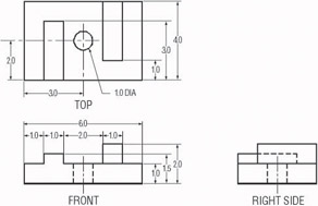
Figure 8.27: Front, top, and side views of a block
Are You Experienced?
Now you can
- draw an exterior elevation from a floor plan
- use grips to copy objects
- add detail to an elevation
- set up, name, and save a User Coordinate System and a new view
- transfer height lines from one elevation to another
- copy, move, and rotate elevations
Introduction
- Getting to Know AutoCAD
- Basic Commands to Get Started
- Setting Up a Drawing
- Gaining Drawing Strategies: Part 1
- Gaining Drawing Strategies: Part 2
- Using Layers to Organize Your Drawing
- Grouping Objects into Blocks
- Generating Elevations
- Working with Hatches and Fills
- Controlling Text in a Drawing
- Dimensioning a Drawing
- Managing External References
- Using Layouts to Set Up a Print
- Printing an AutoCAD Drawing
- Appendix A Look at Drawing in 3D
EAN: N/A
Pages: 159
