Grouping Objects into Blocks
Grouping Objectsinto Blocks
Overview
- Creating and inserting blocks
- Using the Wblock command
- Detecting blocks in a drawing
- Working with AutoCAD’s DesignCenter
- Controlling the appearance of palettes on your screen
Computer drafting gains much of its efficiency from a feature that makes it possible to group a collection of objects into an entity that behaves as one object. AutoCAD calls these grouped objects a block. The AutoCAD tools that work specifically with blocks make it possible to do the following:
- Create a block in your current drawing.
- Repeatedly place copies of a block in precise locations in your drawing.
- Share blocks between drawings.
- Create .dwg files either from blocks or from portions of your current drawing.
- Store blocks on a palette for easy reuse in any drawing.
In general, objects best suited to becoming part of a block are the components that are repeatedly used in your drawings. In architecture and construction, examples of these components are doors, windows, and fixtures or drawing symbols, such as a North arrow or labels for a section cut line (see Figure 7.1). In your cabin drawing, you will convert the doors with swings into blocks. You will then create a new block that you will use to place the windows in the cabin drawing. To accomplish these tasks, you need to learn two new commands.
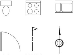
Figure 7.1: Examples of blocks often used in architectural drawings
Making a Block for a Door
When making a block, you create a block definition. This is an invisible entity that is stored in the drawing file and consists of the following:
- The block name
- An insertion point to help you place the block in the drawing
- The objects to be grouped into the block
You specify each of these in the course of using the Make Block command. When the command is completed, the block definition is stored with the drawing file. You then insert the object (as a block) back into the drawing using the Insert Block command.
Before you create a block, you must consider the layers on which the objects to be blocked reside. When objects on the 0 layer are grouped into a block, they take on the color and linetype of the layer that is current when the block is inserted. Objects on other layers retain the properties of their original layers, regardless of which color or linetype has been assigned to the current layer. This characteristic distinguishes the 0 layer from all other layers.
As you define a block, you must decide which—if any—of the objects to be included in the block need to be on the 0 layer before they are blocked. If a block is always going to be on the same layer, the objects making up the block can remain on that layer. On the other hand, if a block might be inserted on several layers, the objects in the block need to be moved to the 0 layer before the block definition is created, so as to avoid confusion of colors and linetypes.
The objects that compose complex blocks can reside on more than one layer.
As you learn to make blocks for the doors, you will also see how layers work in the process of creating block definitions. We’ll create a block for the exterior doors first, using the front door, and call it door3_0 to distinguish it from the smaller interior door. For the insertion point, you need to assign a point on or near the door that will facilitate its placement as a block in your drawing. The hinge point makes the best insertion point.
For this chapter, the Endpoint Osnap should be running most of the time, and Polar Tracking should be off. Follow these steps to set up your drawing:
- If you are continuing from the last chapter, skip to step 2. If you are starting a new session, once AutoCAD is running, click the Open button on the Standard toolbar. In the Select File list, highlight Cabin06b and click Open. If this .dwg file is not in the list, click the arrow to the right of the Look In drop-down list at the top of the dialog box, navigate to your Training Data folder, and then select the file.
- The Roof layer should be visible in the Layers drop-down list on the Object Properties toolbar. Click the list to open it, and then click Doors to make the Doors layer current. The list will close. Click the drop-down list again, and this time click the sun icons for the Roof and Headers layers to freeze them. The suns turn into snowflakes. Then click the Doors layer to close the list. The Doors layer is now current, and the headers and roof lines are no longer visible in the drawing (see Figure 7.2).
We are using the Freeze option for layers this time because we won’t need to see the lines on the Roof and Headers layers for a while.
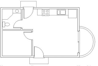
Figure 7.2: The floor plan with the Headers and Roof layers frozen - Check the status bar, and note whether the Osnap button is in the on position. Right-click the Osnap button and choose Settings from the shortcut menu.
- In the Object Snap tab of the Drafting Settings dialog box, be sure the Endpoint check box is marked. Also, be sure Object Snap On is checked.
- Click OK. In the status bar, click Polar off if it is on, and be sure only the Model and Osnap buttons are in the on position.
Now you’re ready to make blocks.
- Click the Make Block button on the Draw toolbar to open the Block Definition dialog box (see Figure 7.3). Notice the flashing cursor in the Name text box. Type door3_0 but do not press .
You can also start the Block command by choosing Draw Block Make or by typing b.
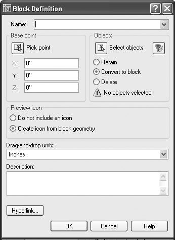
Figure 7.3: The Block Definition dialog box - Click the Pick Point button in the Base Point area. The dialog box momentarily closes, and you are returned to your drawing.
- Zoom in to the front door area. In your drawing, click the Zoom Window button on the Standard toolbar, and make a window around the front door area. The area in the zoom window will fill the screen.
- Move the cursor to the front door area, and position it near the hinge point of the door. When the square appears on the hinge point (see Figure 7.4a), click. This selects the insertion point for the door, and the Block Definition dialog box returns.
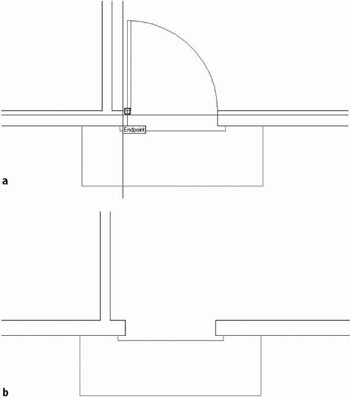
Figure 7.4: The front door opening when picking the hinge point as the insertion point (a), and after creating the door3_0 block and deleting the door and swing (b) - Click the Select Objects button in the Objects area. You are returned to the drawing again. The cursor changes to a pickbox, and the Command window displays the Select objects: prompt.
- Select the door and swing, and then press . You are returned to the Block Definition dialog box. At the bottom of the Objects area, the count of selected objects is displayed. Just above that are three radio buttons. Click the Delete radio button if it’s not already selected.
- Finally, in the middle of the dialog box, be sure Create Icon From Block Geometry is selected, and then click OK to close the dialog box. The door and swing disappear (see Figure 7.4b).
You have now created a block definition, called door3_0. Block definitions are stored electronically with the drawing file. You need to insert the door3_0 block (known formally as a block reference) into the front door opening to replace the door and swing that were just deleted when the block was created.
Inserting the Door Block
You will use the Insert Block command to place the door3_0 block back into the drawing.
- On the Draw toolbar, click the Insert Block button to open the Insert dialog box (see Figure 7.5). At the top, the Name drop-down list contains the names of the blocks in the drawing. In this case, there is only one so far, door3_0, so it is on top. Below the Name list are three areas with the Specify On-Screen option. These are used for the insertion procedure.
You can also start the Insert Block command by choosing Insert Block or by typing I.
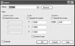
Figure 7.5: The Insert dialog box - Be sure the Specify On-Screen option is checked for all three areas. Also, make sure the Explode check box in the lower-left corner is unchecked.
- Click OK. You are returned to your drawing, and the door3_0 block is now attached to the cursor, with the hinge point coinciding with the intersection of the crosshairs (see Figure 7.6). The Command window reads Specify insertion point or [Scale/X/Y/Z/Rotate/PScale/PX/PY/PZ/PRotate]:.
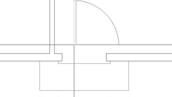
Figure 7.6: The door3_0 block attached to the cursor - With Endpoint Osnap running, move the cursor toward the upper end of the left jamb line in the front door opening. When a colored square appears at the jamb line’s upper endpoint, click. The insertion point has been positioned, and the Command window now displays an additional prompt: Enter X scale factor, specify opposite corner, or [Corner/XYZ]<1>:.
- Press to accept the default of 1 for the X scale factor. The prompt changes to Y scale factor <use X scale factor> :.
- Press again to accept the default for this option. The door3_0 block comes into view, and you can see that its insertion point has been placed at the upper end of the left jamb line and that the block rotates as you move the cursor (see Figure 7.7a). At the Specify rotation angle <0.00>: prompt, press again to accept the default of 0.00. The door3_0 block is placed in the drawing (see Figure 7.7b).
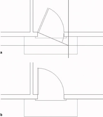
Figure 7.7: The rotation option (a), and the final placement (b)
Each time a block is inserted, you can specify the following on-screen or in the Insert dialog box:
- The location of the insertion point of the block
- The X and Y scale factors
- The Z factor in the dialog box (used for 3D drawings, in AutoCAD only)
- A rotation angle
After you insert blocks, you can stretch or flip them horizontally (the X scale factor) or vertically (the Y scale factor), or you can rotate them from their original orientation. Because you created the door3_0 block from the door and swing that occupied the front door opening, and the size was the same, inserting this block back into the front door opening required no rotation, so we followed the defaults. When you insert the same block into the back door opening, you will have to change the Y scale factor, because the door will be flipped vertically.
Flipping a Block While Inserting It
The X scale factor controls the horizontal size and orientation. The Y scale factor mimics the X scale factor unless you change it. For the next insertion, you will make such a change.
- Click the Zoom Previous button on the Standard toolbar to zoom back out to a full view of the floor plan.
- Click the Zoom Window button, and make a window around the back door area, including plenty of room inside and outside the opening so that you can see the door3_0 block as it is being inserted. You will be zoomed into a close view of the back door (see Figure 7.8).
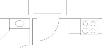
Figure 7.8: The result of the zoom - Use the Erase command to erase the door and swing from the back door opening.
- Choose Insert Block. In the Insert dialog box, door3_0 should still be in the Name drop-down list.
- Click OK. You are returned to your drawing, and the door3_0 block is attached to the cursor.
- Move the cursor to the lower end of the left jamb line. When the colored square appears at that endpoint (see Figure 7.9a), click. The insertion point has been placed, and the prompt reads Enter X scale factor, specify opposite corner, or [Corner/XYZ]<1>:.
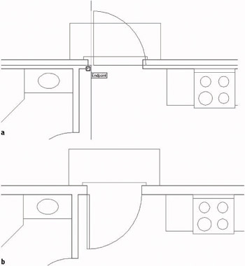
Figure 7.9: Placing the door3_0 insertion point (a), and the block after insertion (b) - Press to accept the default X scale factor of 1. The prompt changes to read Specify Y scale factor <use X scale factor:. In order to flip the door down to the inside of the cabin, you need to give the Y scale factor a value of –1.
- Type -1. Then press again to accept the default rotation angle of 0. The Insert Block command ends, and the door3_0 block is placed in the back door opening (see Figure 7.9b).
Figure 7.9b will look exactly like Figure 7.8.
Nothing has changed about the geometry of the door, but it is now a different kind of object. Before it was a rectangle and an arc; now it’s a block reference made up of a rectangle and an arc.
- Click the Zoom Previous button on the Object Properties toolbar to zoom back out to a full view of the floor plan.
Note When inserting a block, giving a value of –1 to the X or Y scale factor has the effect of flipping the block, much like the Mirror command did in Chapter 4, when you first drew the doors. Because you can flip or rotate the door3_0 block as it is inserted, this block can be used to place a door and swing in any 3'-0" opening, regardless of its orientation.
Doors are traditionally sorted into four categories, depending on which side the hinges and doorknob are on and which way the door swings open. To be able to use one door block for all openings of the same size, you need to know the following:
- How the door and swing in the block are oriented
- Where the hinge point is to be in the next opening
- How the block has to be flipped and/or rotated during the insertion process to properly fit in the next doorway opening
Blocking and Inserting the Interior Doors
Because the interior doors are smaller, you will need to make a new block for them. We could insert the door3_0 block with a 5⁄6 scale factor, but the door thickness would also be reduced by the same factor, and we don’t want that.
On the other hand, it’s a good idea to orient all door blocks the same way, and the bath and bedroom doors are turned relative to the door3_0 block. We’ll move and rotate the bathroom door and its swing like the front door.
- Use Zoom Window to define a window that encloses both the bathroom and bedroom doors. The view will change to a close-up of the area enclosed in your window (see Figure 7.10a).
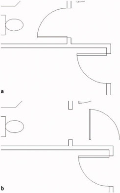
Figure 7.10: The result of a zoom window (a), the bathroom door moved and rotated (b) - Use the Move command to move the bathroom door to the right, and then use the Rotate command to rotate it –90 (see Figure 7.10b).
- Repeat a procedure similar to the one you used to make a block out of the front door and swing to make a block out of the bathroom door and swing. Here is a summary of the steps:
- Start the Block command. (Click the Make Block button on the Draw toolbar.)
- In the dialog box, type door2_6 to name the new block. Don’t press .
- Click the Pick Point button, and pick the hinge point of the bathroom door.
- Click the Select Objects button and pick the door and swing. Then press .
- In the Objects area, click the Delete radio button.
- Click OK. The door and swing disappear.
- Insert the door2_6 block in the bathroom doorway opening. Follow the steps carefully. Here’s a summary of the steps:
- Start the Insert Block command.
- Open the Name drop-down list, select door2_6, and then click OK.
- Pick the left end of the lower jamb line.
- Accept the default of 1 for the X scale factor.
- Accept the default of for the Y scale factor.
- Enter 90 for the rotation.
- Erase the bedroom door, restart the Insert Block command, and insert the door2_6 block in the bedroom door opening. Here are the parameters:
- Check Specify On-Screen for Insertion Point, Scale, and Rotation.
- The insertion point will be at the left endpoint of the upper jamb line.
- The X scale factor will be –1.
- The Y scale factor will be 1.
- The rotation will be 90.
- Zoom Previous (see Figure 7.11).
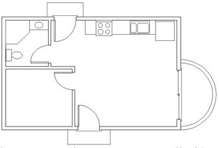
Figure 7.11: The floor plan with all swinging doors converted into blocksTip If you have trouble anticipating how a block such as the door block needs to be flipped or rotated during insertion, don’t worry about it; just make sure to locate the insertion point accurately in the drawing. Then, after the block is inserted, you can flip or turn it by using the Mirror and Rotate commands.
The Fate of Objects Used to Make a Block
The three radio buttons in the Objects area of the Block Definition dialog box represent the options you have for objects transformed into a block:
RetainThe objects remain unblocked. Use this if you want to make several similar blocks from the same set of objects.
Convert To BlockThe objects become a block reference. Use this if the first use of the block has geometry identical to that of the set of objects it is replacing.
DeleteThe objects are automatically erased after the block has been defined. Use this if the first use of the block will be at a different scale, orientation, or location from the set of objects it is replacing.
Note that when we made the first door block, we could have used the Convert To Block option because the door3_0 block replaced the front door and its swing. I decided not to use this option so that I could show you the insertion process with default X and Y scale factors and rotation.
This view looks the same as the view you started with at the beginning of this chapter; see Figure 7.2, shown earlier. Blocks look the same as other objects, and you can’t detect them by sight. They’re useful because you can use them over and over again in a drawing or in many drawings and because the block is a grouping of two or more (and sometimes many more) objects into a single object. The next section will go into how you can detect a block.
Finding Blocks in a Drawing
You can detect blocks in a drawing in at least three ways: by using grips, by using the List command, and by looking at the Properties palette.
Using Grips to Detect a Block
Grips appear on objects that are selected when no command is started. When an object that is not a block is selected, grips appear at strategic places. But if you select a block, by default, only one grip appears, and it’s always located at the block’s insertion point. Because of this, clicking an object when no command is started is a quick way to see if it is a block.
- At the Command: prompt, click one of the door swings. The door and swing ghost, and a colored square appears at the hinge point.
- Press Esc to clear the grip.
- Choose Tools Options to open the Options dialog box, and then click the Selection tab. The Grips areas are on the right side. Enable Grips Within Blocks is unchecked by default. If this option is checked, grips appear on all objects in the block as if they weren’t blocked when you click a block with no command running. Leave this setting unchecked.
- Click OK to close the Options dialog box.
We’ll look at grips in more detail in Chapter 11. You might need to know more about a block than just whether something is one. If that is the case, you will need to use the List command.
Using the List Command to Detect a Block
You can use the List command to learn more about a block.
- Choose Tools Inquiry List.
- Click the front door block, and then press . The AutoCAD Text Window temporarily covers the drawing (see Figure 7.12). In the Text Window, you can see the words BLOCK REFERENCE Layer: DOORS, followed by eight lines of text. These nine lines describe the block you selected.
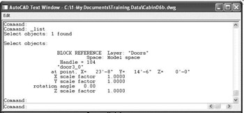
Figure 7.12: The AutoCAD Text WindowThe information stored in the Text Window includes the following:
- What the object is (Block Reference)
- The layer the object is on (Doors layer)
- The name of the block (door3_0)
- The coordinates of the insertion point in the drawing
- The X and Y scale factors
- The rotation angle
- Press F2. The drawing area returns.
- Right-click and choose Repeat List from the shortcut menu.
- At the Select objects: prompt, click one of the arcs that represents the balcony, click one of the wall lines, and press .
- The Text Window is displayed again, and you see information about the arc that you selected, followed by information about the selected wall line.
- Press F2, and then slowly press it a few more times. As you switch back and forth between the Text Window and the drawing, notice that the last three lines in the Text Window are the three lines of text in the Command window of the drawing (see Figure 7.13). The Command window is displaying a strip of text from the Text Window, usually the last three lines.
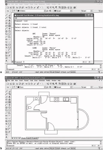
Figure 7.13: Toggling between the Text Window (a) and the drawing with its Command window (b) - Press F2 to display the drawing.
Using the Properties Palette to Detect a Block
In Chapter 6, we used the Properties button on the Standard toolbar to change the individual linetype scale for the ridgeline of the roof. It can also be a tool for investigating objects in your drawing. When the Properties command is started, and only one object is selected, the Properties palette displays data specific to the selected object.
- Click one of the door blocks.
- Click the Properties button on the Standard toolbar. The Properties palette opens.
The data displayed on the palette is similar to that displayed when you used the List command, but in slightly different form (see Figure 7.14). At the top of the dialog box, a drop-down list displays the type of object selected—in this case, a Block Reference.
Block insertion means the same thing as block reference, and both are casually called blocks.
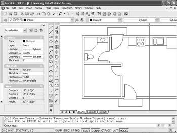
Figure 7.14: The Properties palette docked, with a door block selected - Close the Properties palette by clicking the X in the upper-right corner (upper-left corner if the palette is floating); then press Esc to remove the grip on the door block.
The Properties palette can be docked or floating. The one in Figure 7.14 is docked. If the palette is floating, it may cover part of the toolbars and Command window, but it can be automatically hidden when not in use. I’ll discuss this feature of palettes later in this chapter when we get to the DesignCenter.
Tip The X you need to click to close the Properties palette will be in the upper-left corner of the palette if it is floating, and in the upper-right corner if it is docked.
If you are ever working on a drawing that you did not draw, these tools for finding out about objects will be invaluable. The next exercise on working with blocks will involve placing windows in the walls of the cabin.
Creating a Window Block
You can create all the windows in the cabin floor plan from one block, even though they are four different sizes (see Figure 7.15). You’ll create a window block and then go from room to room to insert the block into the walls.
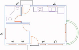
Figure 7.15: The cabin windows in the floor plan
- Click the Layers list on the Object Properties toolbar to open the drop-down list, and click the 0 layer in the list to make it current.
- Right-click the Osnap button on the status bar and choose Settings from the shortcut menu. Add check marks to Midpoint and Perpendicular Osnaps. Then click OK.
- Zoom in to a horizontal section of wall where there are no jamb lines or intersections with other walls, by clicking the Zoom Window button on the Standard toolbar and picking two points to be opposite corners of the zoom window (see Figure 7.16). Because the widths of the windows in the cabin are multiples of 12", you can insert a block made from a 12"-wide window for each window, and you can apply an X scale factor to the block to make it the right width. The first step is to draw a 12"-wide window inside the wall lines.
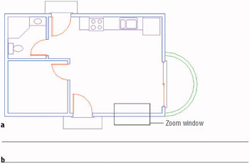
Figure 7.16: Making a zoom window (a) to zoom in to a section of straight length of wall (b) - Start the Line command, and then click the Nearest Osnap button on the Object Snap toolbar or the Osnap flyout on the Standard toolbar. The Nearest Osnap will allow you to start a line on one of the wall lines. It finds the point on the wall line nearest to the point you pick.
Use the Nearest Osnap tool when you want to locate a point somewhere on a line, but aren’t concerned exactly where on the line the point is located.
- Move the cursor to the upper wall line, a little to the left of the center of the screen and, with the hourglass symbol displayed, click. A line begins on the upper wall line.
- Move the cursor to the lower wall line. A colored perpendicular icon will appear directly below the point you previously picked. When it is displayed, click. The line is drawn between the wall lines. Press to end the Line command.
- Start the Offset command. Type 12 to set the offset distance to 12". Pick the line you just drew, and then pick a point to the right of that line. The line is offset 12" to the right. Press to end the Offset command.
- Start the Line command again. Move the cursor near the midpoint of the line you first drew. When the midpoint symbol appears, click. Move the cursor near the midpoint of the line that was just offset. When the Perpendicular or Midpoint symbol appears, click. Press to end the Line command. Your drawing should look like Figure 7.17.

Figure 7.17: Completed lines for the window block
The three lines you’ve drawn will make up a window block. They represent the two jamb lines and the glass (usually called glazing). By varying the X scale factor from 2 to 6, you can create windows 2', 3', 4', and 6' wide.
Before you create the block, you need to decide the best place for the insertion point. For the doors, you chose the hinge point because you always know where it will be in the drawing. Locating a similar strategic point for the window is a little more difficult, but certainly possible. We know the insertion point can’t be on the horizontal line representing the glazing, because it will always rest in the middle of the wall, and there is no guideline in the drawing for the middle of the wall. Windows are usually dimensioned to the midpoint of the glazing line rather than to either jamb line, so we don’t want the insertion point to be at the endpoint of a jamb line. The insertion point will need to be positioned on a wall line but also lined up with the midpoint of the glazing line.
To locate this point, draw a guideline from the midpoint of the glazing line straight to one of the wall lines.
- Press to restart the Line command. Move to a point near the midpoint of the glazing line. When the midpoint symbol appears, click.
- Move to the bottom wall line. When the Perpendicular symbol appears, click. A guideline is drawn from the midpoint of the glazing line that is perpendicular to the lower wall line (see Figure 7.18). The lower endpoint of this line is the location of the window block insertion point. Press to end the Line command. Now you are ready to define the window block.

Figure 7.18: The guideline is completed. - Type b to start the Block command. In the dialog box, type win-1 for the block name and then click the Pick Point button.
- Back in the drawing, with Endpoint, Midpoint, and Perpendicular Osnaps running, move the cursor to the lower end of the guideline you just drew. When the Endpoint symbol appears at that location, click.
If only the Perpendicular Osnap symbol appears, click Endpoint on the Object Snap toolbar, and then try again.
- In the dialog box, click the Select Objects button.
- Back in the drawing, select the two jamb lines and the glazing line, but don’t select the guideline whose endpoint locates the insertion point. Press .
- Back in the dialog box, click the Delete radio button, and then click OK. The win-1 block has been defined, and the 12" window has been erased.
- Erase the guideline using the Erase command.
- Zoom Previous to zoom out to a view of the whole floor plan.
This completes the definition of the block that will represent the windows. The next task is to insert the win-1 block where the windows will be located.
Inserting the Window Block
Several factors come into play when deciding where to locate windows in a floor plan:
- The structure of the building
- The appearance of windows from outside the building
- The appearance of windows from inside a room
- The location of fixtures that might interfere with placement
- The sun angle and climate considerations
For this exercise, we will work on the windows for each room, starting with the bedroom.
Rotating a Block During Insertion
The bedroom has windows on two walls: two 3' windows centered in the front wall 12" apart, and one 4' window centered in the left wall (see Figure 7.19). You’ll make the 4' window first.
- Use a zoom window to zoom in to a view of the bedroom similar to that in Figure 7.19. Click the Polar button on the status bar to turn on Polar Tracking. Polar, Osnap, and Model should now be in the on position.
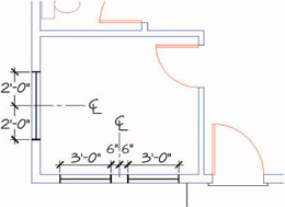
Figure 7.19: The bedroom windows - Create a new layer by clicking the Layer button and then clicking the New button in the Layer Properties Manager dialog box. Layer1 will appear and be highlighted. Type Windows to rename Layer1.
- Click the color square in the Windows row to open the Select Color dialog box, with White highlighted in the Color text box. Type 30 to change the color to a bright orange. (If you don’t have 256 colors available, choose any color.) The Select Color dialog box will close.
- With Windows still highlighted in the Layers Properties Manager dialog box, click the Current button to make the Windows layer current. Then click OK. You are returned to your drawing, and Windows is the current layer.
- Start the Insert Block command (it’s on the Draw toolbar). Open the Name drop-down list in the Insert dialog box. In the list of blocks, click win-1. Be sure all three Specify On-Screen check boxes are selected, and then click OK.
- In your drawing, the 12" window block is attached to the cursor at the insertion point (see Figure 7.20). Note that it is still in the same horizontal orientation that it was in when you defined the block. To fit into the left wall, you will need to rotate it as you insert it.
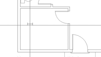
Figure 7.20: The win-1 block attached to the cursor - Move the cursor near the midpoint of the left inside wall line. When a colored triangle appears at the midpoint of that wall line, click.
- You will be prompted for an X scale factor. This is a 4' window, so type 4. For the Y scale factor, type 1.
The Y scale factor will be 1 for all the win-1 blocks because all walls that have windows are 6" wide— the same width as the win-1 block.
- You are prompted for the rotation angle. The window block is now 4' wide and rotates with the movement of the cursor. Move the cursor so that it’s directly to the right of the insertion point. The Polar tracking lines and tool tip appear (see Figure 7.21a). This will show you how the window will be positioned if the rotation stays at 0. Obviously, you don’t want this.
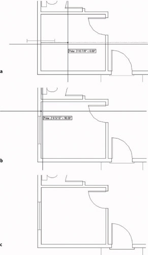
Figure 7.21: Rotating the win-1 block 0 (a), 90 (b), and the final position (c) - Move the cursor so that it is directly above the insertion point. Another tracking line and tool tip appear. This shows what position a 90 rotation will result in (see Figure 7.21b). The window fits nicely into the wall here.
- With the tracking line and tool tip visible, click. The win-1 block is placed in the left wall. The Insert Block command ends (see Figure 7.21c).
Using Guidelines When Inserting a Block
The pair of windows in the front wall of the bedroom are 3' wide and 12" apart and are centered horizontally in the bedroom wall (refer to Figure 7.19, shown earlier). You can use a guideline to locate the insertion points for these two windows.
- Start the Line command, and locate the cursor on the inside, horizontal exterior wall line near its midpoint. When the colored triangle appears at the midpoint of this line, click. A line starts.
- Hold the cursor at a point a few feet below the first point of the line. When the Polar tracking line and tool tip appear, click. Press to end the Line command. This establishes a guideline at the center of the wall. The insertion points for each window will be at its center. The distance between the center of the wall and the insertion point will be half the width of the window, plus half the distance between the windows, in other words, 2 feet.
- Offset the line that you just drew 2' to the right and left (see Figure 7.22). Now you have established the locations for the insertion points of the win-1 blocks, and you are ready to insert them.
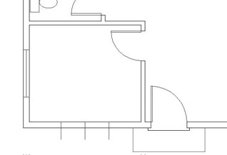
Figure 7.22: Guidelines for the pair of window blocks - Click the Insert Block button on the Draw toolbar to start the Insert Block command. In the Insert dialog box, the win-1 block will still be displayed in the Name drop-down list because it was the last block inserted. Click OK.
- Back in the drawing, the win-1 block is again attached to the cursor. To locate the insertion point, you can choose the upper endpoint of one of the outer guidelines or the intersection of this guideline with the exterior outside wall line. Which one would be better? The second choice requires no rotation of the block, so it’s easier and faster to use that intersection.
- Click the Intersection Osnap button on the Object Snap toolbar, and position the cursor on the outside wall without touching any other lines (see Figure 7.23a). A colored x appears with three dots to its right, along with a tool tip that says “Extended Intersection.” Click.
Now hold the crosshair cursor on the lower portion of the leftmost offset guideline, again without touching any other lines. The x will appear, this time at the intersection of this guideline with the outside wall line, and without the three dots. The tool tip now says “Intersection” (see Figure 7.23b). Click again. The insertion point is set at the intersection of the guideline and the outside wall line.
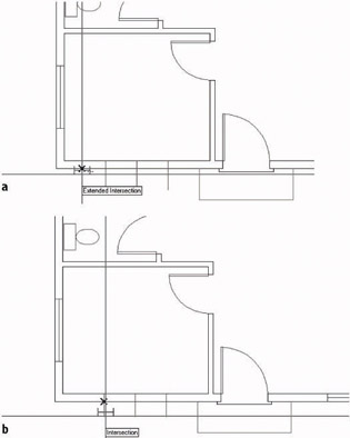
Figure 7.23: Selecting the first line (a) and the second (b) - Type 3 for the X scale factor, and then type 1 for the Y scale factor. At the rotation angle prompt, press to accept the default of 0. The 3' window on the left is inserted in the front wall.
- Repeat this procedure for the other 3' window.
- Erase the three guidelines.
Because you chose to locate the insertion point on the lower of the two wall lines, the block needed no rotation. When finished, the bedroom will look like Figure 7.24.
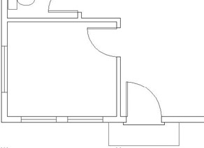
Figure 7.24: The bedroom with all windows inserted
Using Object Snap Tracking and Polar Tracking to Insert a Block
The next room to work on is the bathroom, which has one small window over the sink.
LT users will not have the Otrack button on the status bar. Use the steps in the following “For LT Users” sidebars to achieve the same result.
- Click the Pan button on the Standard toolbar. The cursor changes to a hand.
- Position the hand on the wall between the bedroom and the bathroom, and then hold down the left mouse button and drag the drawing down. When the bathroom is in the middle of the drawing area, release the mouse button. Press Esc or to cancel the Pan command.
You want to create one 2' window, centered over the sink. This time you’ll insert the block without the use of guidelines. Be sure Endpoint and Midpoint Osnaps are running, and turn off Perpendicular Osnap. On the status bar, click the Otrack button to turn on Object Snap Tracking. Polar and Osnap should also be in the on position.
- Start the Insert Block command. Be sure win-1 is in the Name drop-down list, and check that all Specify On-Screen check boxes are marked. Then click OK.
- At the Specify insertion point: prompt, position the crosshair cursor near the midpoint of the line representing the front edge of the sink counter. When a colored triangle appears at the midpoint of that line, put the crosshair right on the triangle momentarily, without clicking. A small + will appear at the midpoint of the line (see Figure 7.25a). When it does, move the crosshair cursor up to the point where the right side of the shower meets the wall line. When the square box appears at the intersection, place the cursor on the box momentarily, again without clicking. Another + will appear there (see Figure 7.25b). You have set two temporary tracking points.
When Otrack is turned on and the + appears at the Object Snap symbol, a tracking point has been acquired. It remains acquired until you place the cursor directly on the Object Snap symbol a second time or until that part of the command is over.
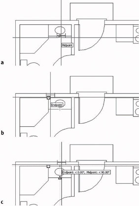
Figure 7.25: Setting a temporary tracking point (a), setting a second tracking point (b), and using the intersection of the two tracking lines to locate the insertion point (c) - Move the cursor to the right, along the lower outside wall line, just in back of the sink. A horizontal tracking line appears and coincides with the wall line. When the crosshair reaches a point directly above the first tracking point, a vertical tracking line appears, and the tool tip identifies the intersection of the two tracking lines as Endpoint: <0.00, Midpoint: <90.00 (see Figure 7.25c). When you see this tool tip, click. The insertion point has been placed on the inside wall line, centered over the sink.
- At the X scale factor prompt, type 2. Then, at the Y scale factor prompt, type 1. Press again to accept the default rotation angle of 0. The 2' window is inserted into the wall behind the sink (see Figure 7.26).
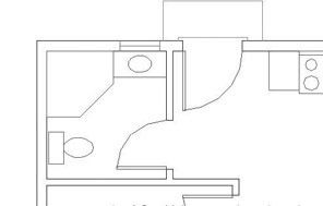
Figure 7.26: The 2' window after insertionTip When using Object Snap Tracking, you will inevitably acquire a tracking point that you don’t need or want. To remove it, place the crosshair cursor on it momentarily. The tracking point will disappear.
For LT Users
LT users should follow these steps for the bathroom window:
- Click the Pan button on the Standard toolbar. The cursor changes to a hand.
- Position the hand on the wall between the bedroom and the bathroom, and then hold down the left mouse button and drag the drawing down. When the bathroom is in the middle of the drawing area, release the mouse button. Press Esc or to cancel the Pan command. You want to create one 2' window, centered over the sink. This time you’ll insert the block without the use of guidelines. Endpoint and Midpoint Osnaps should be the only Osnaps set to be running. On the status bar, Polar and Osnap should be in the on position.
- Start the Insert Block command. Be sure win-1 is in the Name drop-down list, and check that all Specify On-Screen check boxes are marked. Then click OK.
- At the Specify insertion point: prompt, click the Tracking button at the top of the Object Snap toolbar, and then position the crosshair cursor near the midpoint of the line representing the front edge of the sink counter. When a colored triangle appears at the midpoint of that line, click.
- Click the Perpendicular Osnap button on the Osnap toolbar, and then move the cursor up to the inside exterior wall line. When the Perpendicular Autosnap symbol appears, click. Now a line seems to begin on the wall line above the center of the sink. This is the location you want for the insertion point. Press .The insertion point has been placed on the inside exterior wall line, centered over the sink.
- At the X scale factor prompt, type 2.Then, at the Y scale factor prompt, type 1. Press again to accept the default rotation angle of 0.The 2' window is inserted into the wall behind the sink (see Figure 7.26, shown earlier).
You’re more than halfway done with the windows. Just three remain to be inserted: one in the kitchen and two in the living room. We’ll use Object Snap Tracking again on the kitchen window.
For LT users, this next series of steps duplicates the procedure used for the bathroom window. Apply the steps in the previous “For LT Users” sidebar to the kitchen window, using the midpoint of the lower edge of the sink and the upper-right corner of the stove as the points to click.
- Click the Pan button on the Standard toolbar. Then position the hand cursor on the back door swing. Hold down the left mouse button and drag the drawing over to the left until the kitchen is in the middle of the drawing area. Release the mouse button. Then press the Esc key or to cancel the Real Time Pan.
- Zoom in to the sink area, leaving enough of the counter visible to see the line where the right edge of the counter meets the upper wall line.
- You need to insert a 4' window in the back wall, centered behind the sink (see Figure 7.15, shown earlier). Start the Insert Block command to open the Insert dialog box, and then click OK. The win-1 block appears on the cursor.
- At the Specify insertion point: prompt, move the cursor to the lower edge of the sink. When the midpoint triangle symbol appears, place the cursor directly on it until the + appears (see Figure 7.27a).
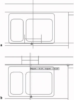
Figure 7.27: The first tracking point is established (a), and the intersection of the two tracking lines is the location of the insertion point (b) - Move the cursor to the point where the right edge of the counter meets the wall line. When the Endpoint square symbol appears, place the cursor directly on the square until the + appears.
- Move the cursor to the left, along the wall line. A tracking line will appear and coincide with the wall line. When the cursor reaches a point directly above the first tracking point, a vertical tracking line will appear and intersect the horizontal one, and the tool tip will read Midpoint: <90.00, Endpoint: <180.00 (see Figure 7.27b). When this happens, click. The insertion point for the win-1 block has been established.
- Type 4 for the X scale factor. Then type 1 for the Y scale factor. For the rotation angle, press again to accept the default angle of 0. The window is placed in the back wall, centered behind the sink.
- Zoom Previous (see Figure 7.28).
Figure 7.28: The inserted window behind the sink
Finishing the Windows
The last two windows to insert are both in the front wall of the living room. You will use skills you’ve already worked with to place them.
- Use the Pan command to move the drawing down to the front wall of the living room. One window is 6' wide. Its right jamb is 12" to the left of the inside corner of the wall. The other one is a circular window, 2' in diameter, positioned halfway between the 6' window jamb and the front doorjamb (see Figure 7.29). We don’t know that distance yet.
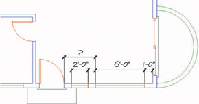
Figure 7.29: The windows in the front wall of the living room - Set the Osnaps so that only Endpoint is running. (To review how to do this, go back to the section in which you created the win-1 block.) Start the Insert Block command, and click OK in the Insert dialog box to select the win-1 block.
To turn Osnaps off, right-click Osnap in the status bar, choose Settings from the shortcut menu, uncheck any Osnaps that you want disabled, and then click OK.
- Click the Temporary Tracking Point Osnap button. Then, with Endpoint Osnap running, pick the lower-right inside corner of the cabin. The insertion point will be positioned to the left of this corner at a distance of 12" in plus half the width of the 6' window, in other words, 4' from the corner.
- Hold the crosshair cursor directly to the left of the point just picked. When the tracking path and tool tip appear, type 4'. This sets the insertion point 4' to the left of the corner, on the inside wall line.
- For the scale factors, type 6, and then type 1.
- For the rotation angle, hold the cursor directly to the right of the insertion point to see the position of the window at 0 rotation. Then hold the cursor directly above the insertion point to see how a 90 rotation would look. Finally, hold the cursor directly to the left for a view of the effect of a 180 rotation. The 180 view is the one you want.
- Type 180. The 6' window is placed in the front wall.
Finally, you need to locate the 2' circular window halfway between the left jamb of the 6' window and the right jamb of the front door opening. Use the Distance command to find out the distance between the two jambs. Then offset one of the jambs half that distance to establish the location of the insertion point on the wall lines. Of the two jamb lines, you must offset the doorjamb because the window jamb is part of the window block and can’t be offset.
- Type di to start the Distance command. With Endpoint Osnap running, pick the upper end of the front doorjamb, and then pick the upper end of the left window jamb. In the Command window, the distance is displayed as 3'-10". You need to offset the doorjamb half that distance to locate the insertion point for the 2' window.
- Start the Offset command, and then type 1'-11 to set the offset distance.
- Pick the doorjamb and type non. Then pick a point to the right of the doorjamb. Press to end the Offset command.
Typing non (none) cancels any running Osnaps for one pick.
- Start the Insert Block command. Click OK to accept the win-1 block. Pick the bottom endpoint of the offset jamb line to establish the insertion point.
- Type 2 for the X scale factor. Type 1 for the Y scale factor.
- For the rotation angle, press to accept the default of 0. The last window is inserted in the front wall, and the Insert Block command ends. Erase the offset jamb line (see Figure 7.30).
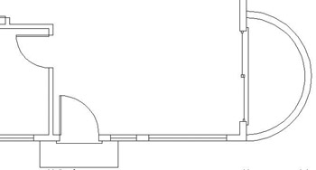
Figure 7.30: The two windows inserted in the front wall of the living room - Type z e to zoom out to the Extents view of the drawing. This changes the view to include all the visible lines. The view fills the drawing area.
Zooming To Extents is one of the zoom options and is the bottom button of the Zoom flyout on the Standard toolbar.
- Type z .85x to zoom out a little from the Extents view, so all objects are set in slightly from the edge of the drawing area (see Figure 7.31).
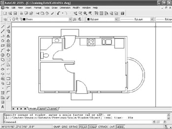
Figure 7.31: Zooming to .85x after zooming to Extents - Save this drawing as Cabin07a.
You have inserted seven windows into the floor plan, each generated from the win-1 block. You created the win-1 block on the 0 layer and then made the Windows layer current, so each window block reference took on the characteristics of the Windows layer when it was inserted.
You can ungroup blocks by using the Explode command. Exploding a block has the effect of reducing the block to the objects that make it up. Exploding the win-1 block reduces it to three lines, all on the 0 layer. If you explode one of the door blocks, it is reduced to a rectangle and an arc, with both objects on the Doors layer because these components of the door block were on the Doors layer when the block was defined.
Revising a Block
If you need to revise a block that has already been inserted in the drawing several times, explode one of these blocks and then modify it. You will need to choose a block whose parameters—the X and Y scale factors and the rotation—were all at the default values: 1 for the scale factors and 0 for the rotation. You inserted all the windows using different X and Y scale factors, so to revise the win-1 block, you’ll need to insert that block one more time, this time using default scale factors and rotation. You can then make changes to the objects that make up the win-1 block reference. When finished with the changes, you can save the changes to the block definition. This redefines the block and updates all associated block references.
Let’s say that the client who’s building the cabin finds out that double glazing is required in all windows. You want the windows to show two lines for the glass. You can’t make such a change in each window block because blocks can’t be modified in this way, and you don’t want to have to change seven windows separately. If you revise the win-1 block definition, the changes you make in one block reference will be made in all seven windows.
| Note |
Using standard commands, you can move, rotate, copy, erase, scale, and explode blocks. They can’t be trimmed, extended, offset, or filleted, and you can’t erase or move part of a block. All objects in a block are grouped together and behave as if they were one object. |
- Start the Insert Block command and click OK to accept the win-1 block to be inserted.
LT users, you will use a slightly different procedure to achieve the same results. Follow the steps in the “Revising a Block with LT” sidebar.
- Pick a point in the middle of the living room. This establishes the insertion point location.
- Press three times to accept the defaults for X and Y scale factors and the rotation angle. The win-1 block is inserted in the living room (see Figure 7.32).
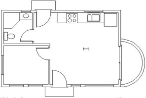
Figure 7.32: The win-1 block inserted into the living room - Choose Modify Xref And Block Editing Edit Reference In-Place.
- Select the new block reference in the middle of the living room to open the Reference Edit dialog box. The win-1 block is identified, and a preview is displayed.
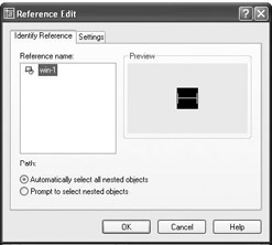
- Click OK. In the drawing, the window block that you just inserted is now white (or black), the rest of the windows have disappeared, the other objects in the drawing have faded slightly, and the Refedit toolbar appears.
- Zoom in to a closer view of the window you just inserted.
- Use the Offset command to offset the glazing line 0.5" up and down. Then erase the original horizontal line (see Figure 7.33). This window block now has double glazing.
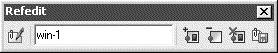
Figure 7.33: The result of the modifications to the win-1 block - On the right side of the Refedit toolbar, click the rightmost button, whose tool tip says “Save back changes to reference.”
- An AutoCAD warning window appears. Click OK. The window block changes back to orange, and the Refedit toolbar closes. The block definition has been revised.
- Erase this block reference; we don’t need it anymore.
- Zoom Previous to view the entire drawing. All windows in the cabin now have double glazing.
- Zoom in to a closer look at the bedroom in order to view some of the modified window block references (see Figure 7.34).
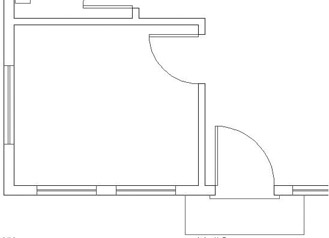
Figure 7.34: Zooming in to see the revised window blocks with double glazing - Zoom Previous to a view of the entire floor plan. Save this drawing as Cabin07b.
Revising a Block with LT
LT users should follow these steps to revise a block:
- Start the Insert Block command, and click OK to accept the win-1 block to be inserted.
- Pick a point in the middle of the living room. This establishes the insertion point location.
- Press three times to accept the defaults for X and Y scale factors and the rotation angle. The win-1 block is inserted in the living room (see Figure 7.32, shown earlier).
- Zoom in to a closer view of this window. Start the Line command. On the Object Snap toolbar, click the Snap To Insert button. (This button has a yellow rectangle and a circle.) Put the cursor anywhere in the window and click. A line is started from the insertion point of the block.
- Pick another point a foot or so below the insertion point, and then end the Line command. This creates a marker for the insertion point. We will use it shortly.
- Click the Explode button at the bottom of the Modify toolbar. Select the new block reference and press .This de-blocks the window. It is now just three lines.
- Use the Offset command to offset the glazing line 0.5" up and down. Then erase the original horizontal line (see Figure 7.33, shown earlier).This window now has double glazing.
- Start the Make Block command. For the name, type win-1. For the insertion point, pick the upper endpoint of the marker line you just drew. For the objects, select the two glazing lines and the two jamb lines, but not the marker line. Click the Delete option in the Objects area, and then click OK.
- A warning box will appear to tell you that a block by this name already exists and to ask if you want to redefine it. Click Yes.
- Erase the marker line.
Continue with step 12.
Sharing Information between Drawings
You can transfer most of the information in a drawing to another drawing. You can do so in several ways, depending on the kind of information that needs to be transferred. You can drag blocks and lines from one open drawing to another when both drawings are visible on the screen. You can copy layers, blocks, and other named objects from a closed drawing into an open one using the DesignCenter. I’ll demonstrate these two features—and touch on three others—as I finish this chapter.
Named objects are, quite simply, AutoCAD objects with names, such as blocks and layers. Lines, circles, and arcs don’t have individual names, so they are not named objects.
Dragging and Dropping between Two Open Drawings
In AutoCAD, several drawings can be open at the same time, just like a word processing program. You can control which one is visible, or you can tile two or more to be visible simultaneously. When more than one drawing is visible, you can drag objects from one drawing to another.
Like most Windows-based programs, AutoCAD 2005 can have multiple drawing files open in a session. When you open the Window menu, the bottom of the menu contains a list of AutoCAD files currently open. Click the file that you want to be active.
- With Cabin07b as the current drawing, click the QNew button on the Standard toolbar. If the Select Template dialog box opens, click the arrow next to the Open button, and then click the Open With No Template - Imperial option. If the Create New Drawing dialog box opens, be sure the Start From Scratch option is selected and click OK. These actions open a blank drawing.
- Choose Window Tile Vertically. The new drawing (called Drawing1) appears alongside Cabin07b (see Figure 7.35).
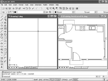
Figure 7.35: The user interface with two drawings tiledEach drawing has a title bar, but only one drawing can be active at a time. At this time, Drawing1 should be active. If it is, its title bar will be dark blue or some other color, and the Cabin07b title bar will be grayed out. If your Cabin07b drawing is active instead, click once in Drawing1.
- Choose Format Units. In the Drawing Units dialog box, change the type of units in the Length area to Architectural, and then click OK.
- Click the Cabin07b drawing to make it the active drawing.
- Zoom to Extents, and then use Realtime Zoom to zoom out a little.
- Use the Layer Control drop-down list to turn off the Doors, Fixtures, Steps, and Windows layers and to make the Walls layer current. The walls and balcony should be the only lines visible.
- Form a selection window to surround the cabin with its balcony. Grips will appear on all lines.
- Place the cursor on one of the wall lines at a point where there are no grips, and then click and hold down the left mouse button. Drag the cursor across the drawing to the center of Drawing1, and then release the mouse button. Drawing1 is now active and contains the lines for the walls and balcony.
- Zoom to Extents in Drawing1, use Realtime Zoom to zoom out a little, and then type ucsicon off (see Figure 7.36).
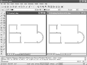
Figure 7.36: The result after dragging lines from one drawing to another - Open the Layer Control drop-down list and note that Drawing1 now has the Walls and Balcony layers.
In this fashion, you can drag any visible objects from one drawing into another, including blocks. If you drag and drop a block, its definition is copied to the new drawing, along with all layers used by objects in the block. If you drag with the right mouse button, you get a few options as to how to place the objects in the receiving drawing.
If you don’t choose to have both open drawings visible at the same time, you can always use the Copy and Paste tools available in most Windows-based programs. Here’s the general procedure:
- Click the Maximize icon in the upper-right corner of the new drawing. The new drawing will fill the screen.
- Click Window in the drop-down menu bar. When the menu opens, notice at the bottom that the open drawings are displayed with the active one checked (see Figure 7.37).
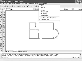
Figure 7.37: The Window menu with Drawing1 active - Click the Cabin07b drawing. It replaces the new drawing as the active drawing and fills the screen. Turn back on the layers that you turned off previously. Leave the Headers and Roof layers frozen.
- Select the fixtures in the kitchen and bath from this drawing, using the selection tools you have learned, and then right-click and choose Copy With Base Point from the shortcut menu. You will be prompted to specify a base point in the Cabin07b drawing. Click the upper-left corner of the building with Endpoint Osnap. Click Esc to turn off the Grips.
- Click Window in the drop-down menu bar. When the menu opens, click Drawing1 to make it active.
- Click the Paste button on the Standard toolbar. Pick the upper-left corner of the building with Endpoint Osnap. The fixtures will be accurately positioned in the new drawing. If you check the layers, you will see that the new drawing now has a Fixtures layer, in addition to the Walls and Balcony layers.
Using AutoCAD s DesignCenter
DesignCenter is a tool for copying named objects (blocks, layers, text styles, and so on) to an opened drawing from an unopened one. You cannot copy lines, circles, and other unnamed objects unless they are part of a block. You’ll see how this works by bringing some layers and a block into Drawing1 from Cabin07b.
- Close Cabin07b. Do not save changes. Maximize the window for Drawing1 if it is not already maximized.
- Click the DesignCenter button on the Standard toolbar. It’s just to the right of the Properties button. The DesignCenter appears on the drawing area. It can be docked, floating, or, if floating, hidden (see Figure 7.38). Your screen may not look exactly like the samples shown here. The tree diagram of file folders on the left half may or may not be visible. Your DesignCenter may be wider or narrower.
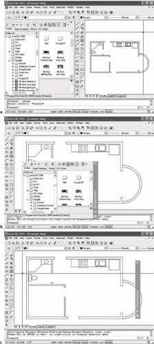
Figure 7.38: The DesignCenter docked (a), floating (b), and hidden (c) - Click the Tree View Toggle at the top of the DesignCenter (the fourth button from the right) a few times to close and open the file folder tree diagram. You can resize the DesignCenter horizontally (and vertically as well, if it is floating), and you can resize the subpanels inside. If Auto-Hide is on, the Design Center hides behind the title bar until you put your cursor on it. Leave the tree view open.
To hide Design Center behind its title bar, right click its title bar and click Auto-Hide.
- On the left half of the DesignCenter window, use the same procedure you use in Windows Explorer to navigate to your Training Data folder.
- When you find it, click the + symbol to the left of the Training Data folder to open it. Now the left side displays a list of your drawings in the Training Data folder. Highlight Cabin07b, and the right side shows the types of objects in Cabin07b that are available to be copied into the current drawing—in this case, Drawing1 (see Figure 7.39a).
- On the left side once again, click the + symbol to the left of Cabin07b. The list of named objects that are on the right panel now appears below Cabin7b in the tree view on the left. Click the Layers icon on the left side. The list of layers in Cabin7b appears in the panel on the right (Figure 7.39b).
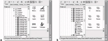
Figure 7.39: The DesignCenter displaying the files in the Training Data folder on the left and accessible objects on the right (a), and types of accessible objects on the left (b) - Click the Views button above the right window of the DesignCenter (the button on the far right). Choose List in the menu that opens. This changes the view of layers displayed into that of a list.
- Use the Shift+ and Ctrl+ keys to help you select all the layers except 0, Balcony, Fixtures, and Walls (see Figure 7.40).
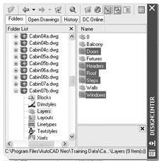
Figure 7.40: The DesignCenter with layers to grab highlighted - Right-click somewhere on the highlighted layers in the right window, and choose Add Layers from the shortcut menu.
If you prefer dragging and dropping, click and hold the left mouse button, drag the cursor onto the drawing, and then release.
- Open the Layer Control drop-down list on the Object Properties toolbar. It will now display all the layers of the Cabin07b drawing, including those you just transferred to the Drawing1 drawing.
Now let’s see how this process works when you want to get a block from another drawing.
The next two figures show DesignCenter in floating mode, with its title bar on the right. Yours may be docked, or it may have its title bar on the left. These variations aren’t significant.
- On the left side of the DesignCenter, click Blocks in the list under the Cabin07b drawing. On the right side, the list of blocks in that drawing is displayed (see Figure 7.41a).
- Click the Preview button at the top of the DesignCenter, and then click door3_0 in the right panel. A picture of the block is displayed in the lower-right corner of the DesignCenter (see Figure 7.41b). You can resize the preview picture window.
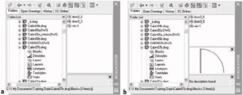
Figure 7.41: The DesignCenter with Blocks selected (a), and with the door3_0 block selected and Preview on (b) - Open the Layer Control list and make Doors the current layer.
- Dock DesignCenter on the left side of the drawing area if it’s not already there, and then zoom in to the front door area of the drawing (see Figure 7.42). Endpoint Osnap needs to be running.
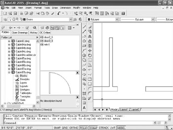
Figure 7.42: Zoomed in to the front door area with the DesignCenter docked - In the DesignCenter, left-click and drag door3_0 from the list over to the drawing. As the cursor comes onto the drawing, the door3_0 block appears. Use Endpoint Osnap to locate the block at the opening, as you did earlier in this chapter (see Figure 7.43).
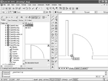
Figure 7.43: Dragging the door3_0 block into Drawing1 from the DesignCenter - Click the Close icon in the upper-right corner of the DesignCenter to close it.
- Keep Drawing1 open in case you want to use it in the practice exercises at the end of this chapter. Otherwise, close it without saving it.
By doing this insertion, the door3_0 block is now a part of Drawing1, and you can reinsert it in that drawing without DesignCenter.
DesignCenter is a simple yet powerful tool. Its function is to find named objects in unopened drawings that you have access to and pull copies of them into your current drawing. These drawings can be on your hard drive, on a network, or on the Internet. At the top of the DesignCenter window, the buttons on the left are tools for navigating through drives and folders to find the files you need to access; the buttons on the right give you options for viewing the named objects in the window.
Design Center Options
Here’s a brief description of the functions of the DesignCenter buttons, from left to right:
LoadOpens the Load dialog box, which you use to navigate to the drive, folder, or file from which you want to borrow named AutoCAD objects.
Left ArrowMoves you one step back in your navigation procedure.
Right ArrowMoves you one step forward in the navigation procedure that you have been using.
UpMoves up one level in the folder/file/named objects tree.
SearchOpens a Search dialog box in which you can search for a file.
Favorites Displays a list of files and folders that you have previously set up.
House IconNavigates to the DesignCenter folder in the AutoCAD program. This folder has subfolders of sample files that contain libraries of blocks and other named objects to import through DesignCenter.
Tree View ToggleOpens or shuts the left panel that displays the logical tree of folders, files, and unnamed objects.
PreviewOpens a preview window at the bottom of the right palette window. When you highlight a drawing or block in the palette window, a preview is displayed. You can resize the preview window.
DescriptionEnables a previously written description of a block or drawing to be displayed. You can resize the description window.
ViewsControls how the items in the palette window are displayed. There are four choices. Clicking this button toggles from one type of view to another. Clicking the arrow to the right displays the list of four options.
Other Ways to Share Information between Drawings
You can transfer information between drawings in several other ways. We’ll look at three of them. First, you can use the Wblock command to take a portion of a drawing and create a new drawing file from the selected objects. Second, you can insert any .dwg drawing file into any other drawing file. Finally, you can create palettes of blocks that can be accessed for any drawing.
Using the Wblock Command
To perform a Wblock operation, you create a new file and then tell AutoCAD which elements of the current drawing you want in the new file. Let’s say you want to create a new .dwg file for the bathroom of the cabin. Here are the steps:
- With Cabin07b as the current drawing, type w to open the Write Block dialog box (see Figure 7.44).
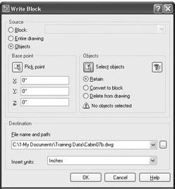
Figure 7.44: The Write Block dialog box - At the top, under Source, click the Objects radio button.
When you select with a crossing window here, you’ll get more than you need, but you can clean up the new drawing later.
- In the middle portion, the Base Point and Objects areas are similar to those for creating a block. For the Base Point, the default is 0,0. Click the Pick Point button, and in the drawing, pick a point just below and to the left of the area to be captured. For the Objects, click Select Objects, and use a crossing window to select everything near the part of the drawing you want. Click the Retain radio button in this area so that the selected material is not deleted from the current drawing.
- In the Destination area, enter a filename for the new drawing, and choose a folder in which to save it.
- In the Insert Units drop-down list, select Inches, in case the new drawing is used in a drawing that has units other than Architectural.
- Click OK. The command ends, and the selected material is now a new drawing file located in the folder that you specified.
You can use the Wblock command in three ways. They are shown as radio buttons at the top of the Write Block dialog box. Here’s a brief description of each.
BlockTo make a drawing file out of a block that’s defined in the current drawing, select the name of the block from the drop-down list at the top, and then follow the procedure in steps 4 through 6 in the previous exercise. When this procedure is followed, the objects in the new drawing are no longer in a block. Wblocking a block has the effect of unblocking it.
Entire DrawingClick this button to purge a drawing of unwanted objects such as layers that have no objects on them and block definitions that have no references in the drawing. You are not prompted to select anything except the information called for in the previous steps 4 through 6. You can keep the same drawing name or type a new one. A preferable way to accomplish the same thing is to use the Purge command. Type purge to open the Purge dialog box and select what to purge.
ObjectsYou select which objects to use to create a new file, as in the previous steps 1 through 6.
Inserting a Drawing into a Drawing
When you insert a drawing into another drawing, it comes in as a block. You use the same Insert Block command that you use to insert blocks, in a slightly different way. For example, say you have Wblocked a portion of Cabin07b.dwg and made a new file called Bath.dwg (see the previous section). Now you want to insert Bath.dwg into DrawingC.dwg. Use this procedure:
- Make DrawingC current.
- Start the Insert Block command.
- In the Insert dialog box, click the Browse button, and then navigate to the folder containing Bath.dwg.
- Open that folder, highlight Bath.dwg, and then click Open to return to the Insert dialog box. The drawing file that you selected is now displayed in the Name drop-down list. At this point, a copy of Bath.dwg has been converted to a block definition in DrawingC.
- Set the insertion parameters, and then click OK.
- Finish the insertion procedure as if you were inserting a block.
You transfer blocks between drawings by dragging and dropping or by using DesignCenter. You can also convert them into .dwg files by using the Wblock command, and you can insert them back into other .dwg files as blocks by using the Insert Block command. They become unblocked when they leave the drawing and reblocked when they enter another drawing.
A Look at AutoCAD’s Palettes
AutoCAD provides a tool called palettes to make blocks and other features immediately accessible for any drawing. Let’s take a brief look at the sample palettes that come with AutoCAD and see how to manage them on the screen.
- Open the Cabin07b drawing, and Zoom it to Extents. Then use Realtime Zoom to zoom out a little.
- If palettes are not already visible in the drawing area, choose Tools Tool Palettes Window to display the palettes (see Figure 7.45). They can be docked on either side of the drawing area, and the navigation bar can be on the left or right side.
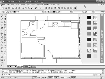
Figure 7.45: The palettes displayed on the screenYour palettes may appear different from those shown in a couple of ways. The ones shown here are positioned on the right side but not docked there. Yours may be transparent, showing your drawing beneath it, or your palettes may be hidden and show only the title bar. In Figure 7.45, four tabs are on the left side, indicating the available palettes. On the right side is the palette title bar with control icons at the top and bottom.
On the palette itself is its content. The hatch sample palettes have hatch patterns and fills (to be discussed in Chapter 9), the Sample Office Project palette contains fills and furniture blocks, and the Command Tools palette has commands that have been copied from the various AutoCAD toolbars.
- Click the Sample Office Project tab to display its content on the palette (see Figure 7.46).
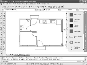
Figure 7.46: The palette for the Sample Office ProjectNotice the scroll bar next to the title bar. This appears when there is more content than the palette can show. The palettes will eclipse part of the right side of the drawing. If you make the palettes transparent, you will be able to see the drawing underneath them.
- Move the cursor to the title bar. Right-click and choose Transparency from the shortcut menu to open the Transparency dialog box (see Figure 7.47). Here you can toggle transparency on and off and adjust the degree of transparency for the palette.
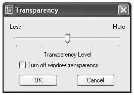
Figure 7.47: The Transparency dialog box - Be sure the Turn Off Window Transparency check box is unchecked, and be sure the Transparency Level slider is at mid-position or on the More side. Then click OK. Now the drawing is visible through the palette (see Figure 7.48).
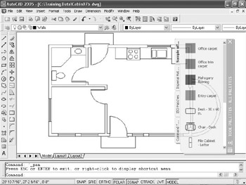
Figure 7.48: The palettes in transparent mode - Put the cursor back on the palette’s title bar. Right-click and choose Transparency from the shortcut menu to open the Transparency dialog box again. Click the Turn Off Transparency check box, and then click OK.
- Right-click the palette’s title bar, and choose Auto-Hide from the shortcut menu. When the menu closes, move the cursor off the palettes. The palettes disappear except for the title bar (see Figure 7.49). When you move the cursor back onto the title bar, the palettes reappear—a handy feature.
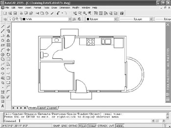
Figure 7.49: The palette title bar with Auto-Hide on
With both Transparency and Auto-Hide active, the palettes are less intrusive and take up less screen area, but remain easily accessible. In Chapter 9, you’ll learn more about palettes and their properties and how to set up new palettes and change existing ones.
| Tip |
When they are in floating mode, the Properties palette and DesignCenter also have the Auto-Hide option, but not the Transparency feature. |
This chapter has outlined the procedure for setting up and using blocks, the Wblock command, and AutoCAD’s DesignCenter. Blocks follow a set of complex rules, some of which are beyond the scope of this book. For a more in-depth discussion on blocks, see Mastering AutoCAD 2005 and AutoCAD LT 2005 by George Omura (Sybex, 2004).
If You Would Like More Practice
Here are some suggestions that will give you some practice in working with blocks, drag-and-drop procedures, and DesignCenter:
- Make blocks out of any of the fixtures in the bathroom or kitchen. Try to decide on the best location to use for the insertion point of each fixture. Then insert them back into the Cabin07b drawing in their original locations. Create them on the 0 layer, and then insert them on the Fixtures layer. Here’s a list of the fixtures:
- Shower
- Bath sink
- Toilet
- Oven/range
- Kitchen sink
- Refrigerator
- At the end of Chapter 5, I suggested creating pieces of furniture for the kitchen, living room, and bedroom of the cabin. If you did that, it will be good practice to make blocks out of those pieces and insert them into the cabin floor plan. If you did not do that exercise, you could do that now and then convert the pieces of furniture into blocks.
- Drag some of the blocks on the Sample Office Palette into the Cabin07b drawing and experiment with ways in which the cabin might be set up as a small office.
- If you work in a profession or trade not directly concerned with architecture or construction, develop a few blocks that you can use in your own work.
- Electrical diagrams are made up many simple symbols, each of which can be a block.
- Cams and gears—or gear teeth—and other engine parts that have been made into blocks can be assembled into a mechanical drawing.
- Plumbing diagrams, like electrical ones, use a variety of symbols repetitively—valves, meters, pumps, joints. These can easily be made into blocks and then reassembled into the diagram.
In each of these examples, choosing the most useful location for the insertion point will determine whether the block that you create will be a handy tool or a big frustration.
Are You Experienced?
Now you can
- create blocks out of existing objects in your drawing
- insert blocks into your drawing
- vary the size and rotation of blocks as they are inserted
- detect blocks in a drawing
- use point filters to locate an insertion point
- revise a block
- drag and drop objects from one drawing to another
- use AutoCAD’s DesignCenter
- use the Wblock command
- open palettes and control their appearance
Introduction
- Getting to Know AutoCAD
- Basic Commands to Get Started
- Setting Up a Drawing
- Gaining Drawing Strategies: Part 1
- Gaining Drawing Strategies: Part 2
- Using Layers to Organize Your Drawing
- Grouping Objects into Blocks
- Generating Elevations
- Working with Hatches and Fills
- Controlling Text in a Drawing
- Dimensioning a Drawing
- Managing External References
- Using Layouts to Set Up a Print
- Printing an AutoCAD Drawing
- Appendix A Look at Drawing in 3D
EAN: N/A
Pages: 159
