Managing External References
Managing ExternalReferences
Overview
- Understanding external references
- Creating external references
- Modifying external references
- Converting external references into blocks
The floor plan of a complex building project may actually be a composite of several AutoCAD files that are linked together as external references to the current drawing. This enables parts of a drawing to be worked on at different workstations (or in different offices) while remaining linked to a central host file. In mechanical engineering, a drawing may similarly be a composite of the various subparts that make up an assembly.
External references are .dwg files that have been temporarily connected to the current drawing and are used as reference information. The externally referenced drawing is visible in the current drawing. You can manipulate its layers, colors, linetypes, and visibility, and you can modify its objects, but it is not a permanent part of the current drawing.
External references are similar to blocks in that they behave as single objects and are inserted into a drawing in the same way. But blocks are part of the current drawing file, and external references are not.
Blocks can be exploded back to their component parts, but external references cannot; however, external references can be converted into blocks and become a permanent part of the current drawing. In Chapter 7, you were able to modify the window block, and in so doing, update all instances of the window block in the drawing without having to explode the block. With an external reference—usually called an Xref—the same mechanism can be applied. To manage external references, you need to learn how to set up an Xref, manipulate its appearance in the host drawing, and update it.
Before you set up the Xref, you will create a site plan for the cabin. You will then Xref the cabin drawing into the site drawing. In Figure 12.1, the lines of the cabin floor plan constitute the Xref, and the rest of the objects are part of the host drawing. After these exercises, we will look at a few ways that design offices use external references.
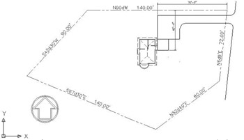
Figure 12.1: The site plan with the cabin as an external reference
Drawing a Site Plan
The site plan you will use has been simplified so that you can draw it with a minimum of steps and get on with the external referencing. The following are essential elements:
- Property lines
- Access road to the site
- North arrow
- Indication of where the building is located on the site
The first step is to draw in the property lines.
Using Surveyor Units
You draw property lines using Surveyor units for angles and decimal feet for Linear units. In laying out the property lines, you will use relative polar coordinates, so you will enter coordinates in the format @distance<angle, in which the distance is in feet and hundredths of a foot, and the angle is in Surveyor units to the nearest minute.
Surveyor Units
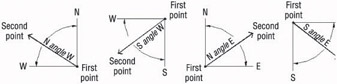
Surveyor units, called bearings in civil engineering, describe the direction of a line from its beginning point. The direction (bearing), described as a deviation from the north or south toward the east or west, is given as an angular measurement in degrees, minutes, and seconds. The angles used in a bearing can never be greater than 90, so bearing lines must be headed in one of the four directional quadrants: northeasterly, northwesterly, southeasterly, or southwesterly. If north is set to be at the top of a plot plan, south is down, east is to the right, and west is to the left. Thus, when a line from its beginning goes up and to the right, it is headed in a northeasterly direction. And when a line from its beginning goes down and to the left, it is headed in a southwesterly direction, and so on. A line that is headed in a northeasterly direction with a deviation from true north of 30 degrees and 30 minutes is shown as N30d30' E in AutoCAD notation.
With the Surveyor unit system, a sloping line that has an up-and-to-the-left direction would have a down-and-to-the-right direction if you started from the opposite end. So in laying out property lines, it is important to move in the same direction (clockwise or counterclockwise) as you progress from one segment to the next.
Laying Out the Property Lines
You will set up a new drawing and then start at the upper-right corner of the property lines and work your way around counterclockwise.
- Open Cabin11a from your training folder. Choose File Save As, and save the drawing as Cabin12a.
- Click the QNew button on the Standard toolbar to open the Create New Drawing dialog box. Click Start From Scratch, and then click OK. (If the Select Template dialog box opens instead of the Create New Drawing dialog box, open the Open drop-down list and select Open With No Template - Imperial.)
- From the menu bar, choose Format Units to open the Drawing Units dialog box, and change the precision in the Length area to two decimal places (0.00).
- In the Angle area, open the Type drop-down list and select Surveyor’s Units. Then change the precision to the nearest minute (N0d00' E). Click OK. You will need an area of about 250' 150' for the site plan.
- Open the Format menu again and choose Drawing Limits. Press to accept the default 0.00,0.00 for the lower-left corner. Type 250,150. Don’t use the foot sign.
We are using Decimal linear units in such a way that 1 decimal unit represents 1 foot. The foot symbol (') is used only with Architectural and Engineering units.
- Right-click the Snap button on the status bar, and then choose Settings. Change Snap Spacing to 10.00, and change Grid to 0.00. Then click the Grid check box to turn on the grid, but leave Snap off. Click OK.
- In the drawing, type z a. Then zoom to .85x to see a blank space around the grid (see Figure 12.2).
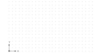
Figure 12.2: The site drawing with the grid on - Create a new layer called Prop_line. Assign it a color and make it current.
- Start the Line command. For the first point, type 220,130. This will start a line near the upper-right corner of the grid.
- Be sure Snap is turned off. Then type: @140<n90dw
@90<s42d30'w
@140<s67d30'e
@80<n52d49'e
c
The property lines are completed (see Figure 12.3).
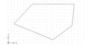
Figure 12.3: The property lines on the site drawing
Drawing the Driveway
The driveway is 8' wide and set 5' from the horizontal property line. The access road is 8' from the parallel property line. The intersection of the access road line and the driveway lines forms corners, each with a 3' radius. The driveway extends 70' in from the upper-right corner of the property.
Let’s lay this out now.
- Choose Format Units from the menu bar. Change the units to Architectural and the angular units to Decimal degrees. Then set the length precision to 1/16" and the angular precision to 0.00. Click OK. Because of the way AutoCAD translates decimal units to inches, your drawing is now only 1⁄12th the size it needs to be. (Use the Distance command to check it.) You will have to scale it up.
- Click the Scale button on the Modify toolbar.
You can also start the Scale command by choosing Modify Scale from the menu bar or by typing sc.
- Type all. For the base point, type 0,0.
- At the Specify scale factor or [Reference]: prompt, type 12. Then click Grid on the status bar to turn off the grid.
- Zoom to Extents, and then zoom out a little. The drawing looks the same, but now it’s the correct size. Check it with the Distance command, which you encountered in Chapter 7.
- Offset the upper, horizontal property line 5' down. Offset this new line 8' down.
- Offset the rightmost property line 8' to the right (see Figure 12.4a).
- Create a new layer called Road. Assign it the color White, and make the Road layer current.
- Click the new lines, open the Layer Control drop-down list, and click the Road layer to move the selected lines to the Road layer. Press Esc to remove the grips.
- Extend the driveway lines to the access road line. Trim the access road line between the driveway lines.
- Fillet the two corners where the driveway meets the road, using a 3' radius (see Figure 12.4b).
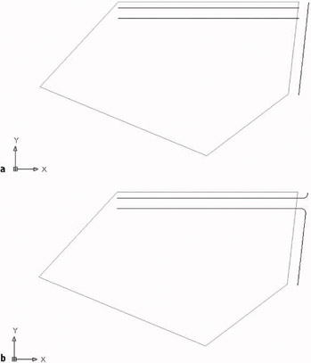
Figure 12.4: Offset property lines (a), and the completed intersection of the driveway and access road (b)
Finishing the Driveway
A key element of any site plan is information that shows how the building is positioned on the site relative to the property lines. Property lines are staked out by surveyors. The building contractor then takes measurements off the stakes to locate one or two corners of the building. In this site, you need only one corner because we are assuming the cabin is facing due west. A close look at Figure 12.1, shown earlier in this chapter, shows that the end of the driveway lines up with the outer edge of the back step of the cabin. Below the driveway is a square patio, and its bottom edge lines up with the bottom edge of the back step. So the bottom corner of the back step coincides with the lower-left corner of the patio. This locates the cabin on the site (see Figure 12.5).
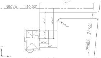
Figure 12.5: The driveway and patio lined up with the cabin
Imagine the site being on a bluff of a hill overlooking land that falls away to the south and west, providing a spectacular view in that direction. To accommodate this view, we will want to change the orientation of the cabin when we Xref it into the site drawing.
- On the status bar, turn on Polar. Then draw a line from the upper-right corner of the property lines straight up to a point near the top of the screen.
- Offset this line 70' to the left. This will mark the end of the driveway.
- Draw a line from the lower endpoint of this offset line down a distance of 40'-4". Then, using Polar Tracking, continue this line 11'-4" to the right.
- Offset the 40'-4" line 11'-4" to the right. Offset the newly created line 11'-4" to the right as well.
- Offset the upper driveway line 24' down. These are all the lines you need to finish the site plan (see Figure 12.6a).
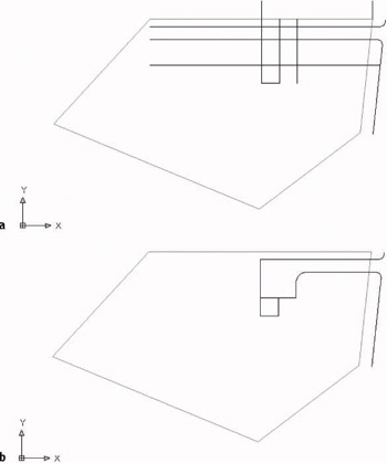
Figure 12.6: The offset lines (a), and the finished driveway and patio (b) - Finish the driveway and patio by using the Trim, Fillet, and Erase commands as you have in previous chapters. The radius of the corner to fillet is 6' (see Figure 12.6b).
- Make the 0 layer current, draw a north arrow, and place it in the lower-left corner.
- Open the Layer Properties Manager dialog box, and change the linetype for the Prop_line layer to Phantom. (You will have to load it; see Chapter 6.)
- Type ltscale, and then type 100. You will see the phantom linetype for the property lines.
- Save this drawing in your training folder as Site12a.
This completes the site plan. The next step is to attach the cabin drawing as an external reference into the site plan.
Setting Up an External Reference
When you set up an external reference, you go through a process similar to that of inserting a block into a drawing, as you did in Chapter 7. You select the drawing to be referenced and specify the location of its insertion point. There are options for the X scale factor, Y scale factor, and rotation angle, as there are for inserting blocks. And here, as with blocks, you can set up the command so that it uses the defaults for these options without prompting you for your approval.
The External Reference Dialog Box
You can run all external reference operations through the Xref Manager dialog box, which you can open by choosing Insert Xref Manager from the menu bar or by typing xr. To set up a new external reference, choose Insert External Reference.
There is also a Reference toolbar that has five command buttons related to Xrefs. You open it the same way you opened the Dimension toolbar in the last chapter: Right-click any button on the screen, and then choose Reference from the shortcut menu. But unless you’re an advanced user, I don’t recommend using the Reference toolbar while working through this chapter, for two reasons. First, there are seven other buttons on the toolbar used for Image commands that allow you to import raster drawings into AutoCAD, an operation not covered in this book. Second, the toolbar does not include all the Xref commands we will be covering. If you have already opened this toolbar, click the X in the upper-right corner to close it.
- With Site12a as the current drawing, create a new layer called Cabin. Use the default color of White/Black and make the Cabin layer current.
- Choose Insert External Reference to open the Select Reference File dialog box.
- Locate the Training Data folder (or the folder that your training files are stored in) and select Cabin12a.dwg. Then click Open to open the External Reference dialog box.
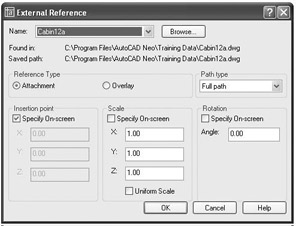
The file being referenced, Cabin12a, is displayed in the drop-down list at the top of the dialog box, with the full path of the file’s location just below. The bottom half contains three options for the insertion process, which are like those in the Insert dialog box that you used for inserting blocks in Chapter 7. Note that only the insertion point is specified on-screen. The Scale and Rotation options should be set to use their default settings. If they are not, click the appropriate check boxes so that this dialog box matches that in the previous graphic.
- Be sure Attachment is selected in the Reference Type area, and then click OK. A technical AutoCAD message may appear that doesn’t concern us right now.
- If the message appears, click OK to close it. You return to your drawing, and the cabin drawing appears and moves with the crosshair cursor.
- Pick any point within the property line and to the left of the patio to be the insertion point. The Xref drawing is attached and appears in the site plan (see Figure 12.7).
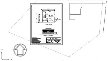
Figure 12.7: The Cabin12a drawing attached to the Site12a drawing
The attached Xref appears exactly as it did when it was the current drawing. When we use this file as part of a site plan, we don’t want all the information in Cabin12a to be visible. In fact, we want most of the information invisible. We will accomplish this by freezing many of the layers in the Xref drawing.
Controlling the Appearance of an Xref
Xref layers will be part of the list of layers for the current, or host, drawing. But the name of the Xref file is added to the front of the layer’s previous name, separated from the layer’s previous name by a vertical bar ( | ).
- Click the Layer button on the Object Properties toolbar to open the Layer Properties Manager dialog box. Right-click the Name heading at the top of the column of layer names, and then choose Maximize Column from the shortcut menu that opens. Layers from the Xref drawing all have Cabin12a and a vertical bar before the name of the layer, as in Cabin12a|Balcony. Before changing any aspect of the layers, we want to save the layer’s state as it is now.
- Click the Layer States Manager button near the upper-left corner to open the Layer States Manager dialog box.
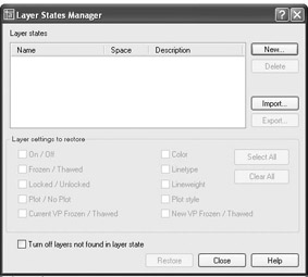
- Click New to open the New Layer State To Save dialog box.
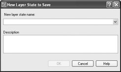
- In the New Layer State Name text box, type as is but don’t press yet. Enter a description of the layer state you are saving, such as, “ State of layers just after attaching Cabin 12a.” Then press or click OK to return to the Layer States Manager dialog box.
- In the Layer Settings To Restore area, be sure check marks are in the On/Off, Frozen/Thawed, Locked/Unlocked, Color, and Linetype check boxes. Don’t concern yourself with the other boxes.
- Click Close. Now we can make a few changes in the Layer Properties Manager dialog box.
- Freeze all layers beginning with Cabin12a except:
- Cabin12a|Balcony
- Cabin12a|Roof
- Cabin12a|Steps
- Cabin12a|Walls
Here’s how to do this:
- Click the Cabin12a|Dim1 layer.
- Hold down the Shift key and click the Cabin12a|Windows layer.
- Hold down the Ctrl key and click the last three layers listed earlier to deselect them. The Cabin12a|Balcony layer was not originally selected.
- Click one of the sun icons for a highlighted layer.
- Click OK to close the dialog box and view the drawing (see Figure 12.8).
We are freezing layers here rather than turning them off because we don’t expect them to be made visible again for quite a while.
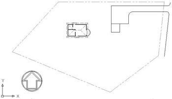
Figure 12.8: The site plan with most of the cabin layers frozen
You can resize the Layer Properties Manager dialog box to display more layers at a time. Depending on the size of your screen and your screen resolution, you might be able to view all Xref layers at once.
Using Layer Filters
On the left side of the Layer Properties Manager dialog box, take a look at the Layer Filter Tree View box. Here’s where you control which layers are displayed in the Layer List on the right.
- Click the plus sign (+) next to Xref. Cabin12a is displayed.
- Click Cabin12a. Now only the Xreffed layers are shown in the layer list. The 0, Defpoints, Prop_line, and Road layers are not shown.
The Defpoints layer holds information about dimensions and is always part of the host file layers.
- In the lower-left corner of the dialog box, click the Invert Filter check box. This reverses the effect of the Cabin12a filter and displays all layers except the Cabin12a Xreffed layers.
- Uncheck the Invert Filter check box; then click the New Property Filter button in the upper-left corner of the dialog box. This displays the Layer Filter Properties dialog box (see Figure 12.9) in which you can set up and manage your own filters.
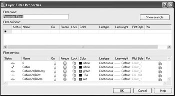
Figure 12.9: The Layer Filter Properties dialog boxLet’s set up a filter for the four layers in the Xref that we are going to keep visible in the site drawing.
- In the Filter Name text box, type Cabin visible, but don’t press yet. In the Filter Definition area, the various properties of layers are the headers of the columns. We can define our new filter by describing the part of the filters’ names that the four layers have in common and by specifying that the filters need to be thawed. The Filter Preview area will show the list of layers that qualify to pass through the filter as we define it.
- Click in the box below Name in the Filter Definition area. A cursor appears in the box followed by an asterisk.
- Type Cabin12a| but don’t press yet. In the Filter Preview area, only the Xref layers are visible.
- Click in the box below Freeze, click the down arrow, and then click the sun. In the Filter Preview area, only the four visible Xref layers are listed (see Figure 12.10).
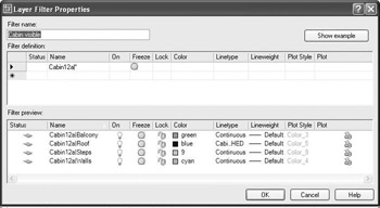
Figure 12.10: The new Cabin Visible filter in the Layer Filter Properties dialog box - Click OK. In the Layer Properties Manager dialog box, Cabin visible is now displayed in the list of layers in the Layer Filters Tree View box on the left.
- Click All in that list. All layers are listed. Then click Cabin visible. Only the four layers we didn’t freeze are listed (see Figure 12.11).
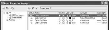
Figure 12.11: The result of the Cabin Visible filter in the Layer Properties Manager dialog box
Using the Group Filters Option
In the Layer Properties Manager dialog box, in the upper-left corner, the second of the three buttons is the New Group Filter button. Click this button to create a filter made up of layers that have some characteristic in common, such as those layers containing any kind of text. For example, to filter out all layers that don’t have text on them, click the New Group Filter button, and rename the filter to, for example, Text Layers. You can then add layers to the new filter in two ways:
- Click All, and then drag layers that have text in them onto the new filter’s name in the Layer Filter Tree View box.
- Right-click the new filter and then choose Select Layers Add from the shortcut menu. In the drawing, click on objects whose layers you want in the filter. When finished, right-click again.
After the filter is set up, it behaves just like the Properties filters.
We have one more change to make to these four layers. Because we want the visible parts of the cabin to read as a unit, we will assign the same color to all the thawed cabin layers. Let’s make those changes now.
- Right-click one of the four layers, and then choose Select All from the shortcut menu. Change the color of one of the selected layers to a dark green. The rest of the selected layers will also change to a dark green. Click All in the Layer Filters Tree View box. This is a new layer state, so let’s save it as we did the previous layer state.
- Click the Layer States Manager button near the upper-right corner to open the Layer States Manager dialog box.
- Click New to open the New Layer State To Save dialog box.
- In the New Layer State Name text box, type Xref but don’t press yet. Enter a description of the layer state you are saving, such as, “ State of Cabin layers for Xref.” Then press or click OK to return to the Layer States Manager dialog box.
- In the Layer Settings To Restore area, be sure check marks are in the On/Off, Frozen/Thawed, Locked/Unlocked, Color, and Linetype check boxes. Don’t concern yourself with the other boxes.
- Click Close. The cabin is now all one color.
Moving and Rotating an Xref
Now you need to move the cabin and rotated it to its position next to the patio.
- Zoom in to a view where the cabin and the left side of the patio are visible.
- Start the Rotate command and click the cabin. The entire cabin is selected. Press .
- To specify a location for the base point, click anywhere near the middle of the cabin, and then type –90. The cabin is rotated to the correct orientation (see Figure 12.12a).
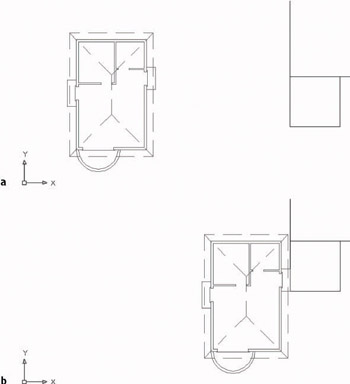
Figure 12.12: The cabin rotated (a), and positioned next to the patio (b). - Be sure Endpoint Osnap is running. Then use the Move command to move the lower-right corner of the back step to the lower-left corner of the patio (see Figure 12.12b).
- Zoom Previous to a view of the whole site. The cabin is oriented correctly on the site (see Figure 12.13). This is the same view as in Figure 12.1 (shown earlier).
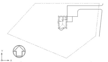
Figure 12.13: The cabin Xref is located on the site drawing.
You have established Cabin12a as an external reference in this drawing and modified the appearance of some of the Xref’s layers. The next step is to make some revisions to Cabin12a and see how this affects the Xref.
Using the Layer States Manager
You use the Layer States Manager tool to save the current setup of various properties and states of layers in the current drawing. You can activate it by clicking the Layer States Manager button in the Layer Properties Manager dialog box. All the operations for controlling the Layer States Manager are performed through this dialog box. Here’s how to work your way through it.
To set up a new layer state, follow these steps:
- In the Layer Properties Manager dialog box, set up the layer properties and states as you want them to be saved, and then click the Layer States Manager button.
- In the Layer States Manager dialog box, enter a name for the new layer state.
- In the Layer Settings To Restore area, check the layer settings you want to save as part of the new layer state. (You will learn about Plot/No Plot, Current VP Frozen/Thawed, Lineweight, Plot Style, and New VP Frozen/Thawed in Chapters 13 and 14.)
- Click Close to save the new layer state.
You also use the Layer States Manager dialog box to manage existing layer states. Here are its features:
Layer States List BoxDisplays a list of previously set up layer states.
Restore ButtonRestores the layer state that is highlighted in the Layer States list box.
Delete ButtonDeletes a layer state. This does not affect the current layer setup.
Import ButtonImports a .las file as a new layer state in the current drawing.
ExportExports the chosen saved layer state to be saved as a .las file.
To modify a layer state, restore it to be the current layer state, and then change it.To rename a layer state, highlight it, click its name, and type the new name.
Modifying an Xref Drawing
You can modify an Xref drawing by making it the current drawing, making the modification, saving the changes, making the host drawing current, and reloading the Xref. AutoCAD users can also modify an Xref by using a special modification command while the host drawing is current. We’ll start by opening Cabin12a and making an addition to it. Then we’ll make Site12a current again and use AutoCAD to modify Cabin12a as an Xref.
Before we do anything, however, we need to change a setting so that the new layer states and the changes we have made to the layers of the Xref are saved with the host file.
- Type visretain. If the value in the angle brackets is set to 1, press . Otherwise, type 1 to set the value to 1. This will allow you to save the layer settings of the Xref layers and the new layer states with the current file.
- Choose File Save As and save the current file as Site12b.
- Click Window on the menu bar. At the bottom of the menu, Cabin12a should be displayed next to 1.
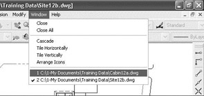
- Select Cabin12a.dwg to make it the current drawing. Notice that the wall, roof, balcony, and steps in the floor plan of this drawing retain their original colors and are not dark green, and notice that most of the other layers in the drawing are visible.
Modifying an Xref by Making It the Current Drawing
Because we found such a spectacular site for the cabin, we want to add a deck around what was originally the front door and is now the west-facing entrance.
- Zoom in to the area that includes the floor plan and the area between it and the front elevation.
- Create a new layer called Deck. Assign it a color and make it current. Next, adjust the drawing’s layers to give yourself some room to make this revision.
- Turn off the following layers:
- Dim1
- F-elev
- Tblk1
- Text1
- Any Hatch layers that aren’t already frozen
- The drawing will look like Figure 12.14. Use the Pline command to draw a deck across the front of the cabin that extends down 10'. (The Polyline command was introduced in Chapter 10.)
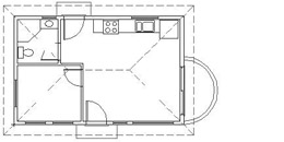
Figure 12.14: The view with selected layers frozen - Make sure the Endpoint Osnap is running. Then click the Polyline button on the Draw toolbar and pick the lower-left corner of the cabin walls to start the Pline.
- Type w. Then type 0 to reset the Pline width to zero.
The Command window shows the polyline width currently set to 3", from when you drew the border and title block in Chapter 10.
- Be sure Polar is clicked on. Then hold the crosshair cursor straight down below the first point picked and type 10'.
- Click the Otrack button on the status bar to turn on Otrack mode. Hold the crosshair cursor on the lower-right corner of the cabin walls for a moment, until a cross appears. When it does, begin moving the crosshair cursor directly down, while staying on the tracking path. A small x will appear at the intersection of the vertical tracking path and the horizontal polar tracking line, as well as a Polar & Endpoint tool tip (see Figure 12.15a). When you see the small x and tool tip, click once to establish the second line segment. A horizontal line is drawn that parallels the front wall of the cabin and is 10' below it.
Step 8 is for AutoCAD users only. LT users should follow step 8 in the following sidebar.
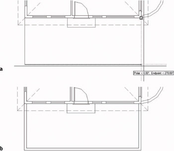
Figure 12.15: The vertical tracking path (a), and the offset deck line (b)
Step 8 for LT Users
LT users should follow this step:
- Click the Tracking button at the top of the Osnap toolbar, and then put the cursor on the lower-right corner of the cabin walls. When the square appears, click. Move the cursor to the bottom end of the 10' polyline segment you just drew. When the square appears, click. Press . A horizontal line is drawn that parallels the front wall of the cabin and is 10' below it.
Now continue with step 9.
- Finally, pick the lower-right corner of the cabin walls to complete the outline of the deck. Press to end the Pline command.
- Offset this polyline 6" to the inside (see Figure 12.15b). When a polyline is offset, all segments are automatically offset together and filleted to clean up the corners. (The fillet radius is zero for this operation, even if it’s currently set to a nonzero value.)
This concludes the modifications we will make to the Cabin12a drawing in this exercise, though we will make some more later. Now we can return to the Site12b drawing.
- It is important to save the file at this point. Keep the name as Cabin12a; otherwise the Xref in the Site12b drawing will not be updated to include the deck. This is a revision to the Cabin12a drawing that has been externally referenced into the Site12b drawing. Save Cabin12a, and then choose Window Site12b to switch back to the site drawing. If you are using AutoCAD, a balloon message will appear in the lower-right corner to tell you that an external reference file has changed and that it might need reloading.
- On the drop-down menus, choose Insert Xref Manager to open the Xref Manager dialog box.
Once an external reference has been set up, you will use the Xref Manager dialog box to control the linkage between the Xref and the host drawing. When the host drawing is opened, it reads the latest saved version of a drawing that is externally referenced to it. Now that we have changed Cabin12a, we need to update the Cabin12a Xref to reflect those changes.
- In the list of Xref files, click Cabin12a to highlight it. All the buttons on the right side of the dialog box are now available, and—in AutoCAD only—when you put the cursor on the Needs… text in the Status column, a tool tip–like box reads “Needs reloading.”
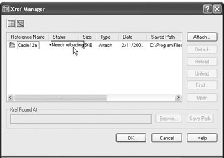
- Click the Reload button, and then click OK. You are returned to the Site12a drawing; the new deck has been added (see Figure 12.16).
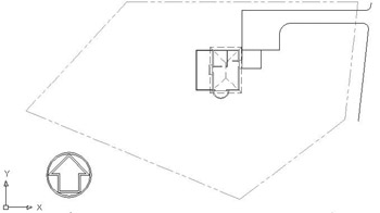
Figure 12.16: The Site12b drawing with the revised Xref of the cabin - Save this drawing. It’s still called Site12b.
In this exercise, you have seen how a host drawing is updated when the drawing that is externally referenced is made current, modified and saved, and then updated as an Xref. You also saw how you can control the appearance of objects in the Xref drawing from the host drawing by working with the Xref layers. This is a good example of the power of layers. You can set them up one way in the actual drawing and another way in the Xref of that drawing in a host file. In fact, you can Xref the same drawing into any number of host files; have the layer characteristics of visibility, color, and linetype be different in each host file; and save them as such with each host file. Xref is a powerful feature of AutoCAD, and you will learn more about the possible applications of this tool toward the end of this chapter.
Modifying an Xref from within the Host Drawing
|
|
In Chapter 7, we used the In-Place Xref And Block Edit command to update the window block. You can use the same tool here for editing an Xref while the host drawing is the current drawing. You can’t create a new layer with this tool, but many of the regular editing commands are available when you use it. We’ll make a few modifications related to the new deck to illustrate this feature. |

AutoCAD LT 2005 doesn’t have the In-Place Xref And Block Edit feature. To keep your drawing current with the book, read through the following section to see what changes we are making, and then use the technique for modifying Cabin12a that we used in the previous section to draw the new deck. That is, make Cabin12a current, make the modifications described in the following exercise, save the changes, make Site12b current, and use the Xref Manager to reload Cabin12a. Then continue with step 9 in the following exercise.
- Use the Window menu to switch to Cabin12a, and then close this file. (Choose File Close.) Site12b will return to the drawing area. Make the 0 layer current.
- Zoom in to the cabin floor plan on the site plan (see Figure 12.17a). We need to erase the old front step and fill in the roof lines that were broken out to make room for the room label text.
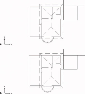
Figure 12.17: Zooming in for a close-up view of the Xref cabin (a), and the Xref cabin with the step erased and the roof lines filled in - On the drop-down menus, choose Modify Xref And Block Editing Edit Reference In-Place. You are prompted to select the Xref to edit.
- Click anywhere on the cabin; it’s all one object for now. The Reference Edit dialog box opens. On the Identify Reference tab, Cabin12a is listed as the selected Xref, and a preview window illustrates the Xref drawing. At the bottom, select the Prompt To Select Nested Objects radio button.
- Click OK. At the Select nested objects: prompt, click the six roof hip lines that need repair, the roof ridge line, and the three lines that make up what was formerly the front step. Then press . The Command: prompt returns to the command window. The Refedit toolbar appears.
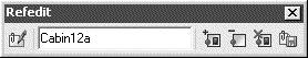
You are now free to use many of the Draw and Modify commands on the lines that we just selected. They are displayed in a slightly darker color than the unselected lines.
- Use the Erase command to erase the three lines of the front step and the three broken roof line segments that connect to the ridgeline.
The roof lines needing repair may appear normal in this view because they are dashed. As you select them, you will see that they are broken.
- Use the Fillet command with a radius of zero to extend the three remaining broken roof line segments to the ridgeline (see Figure 12.17b).
Tip The correct fillet will require you to use the ridgeline as one of the lines to fillet, rather than the unbroken hip line, because the latter line was not selected to be part of the Xref edit in step 5.
- Move to the Refedit toolbar. On the far right end, click the Save Back Changes To Reference button. When the warning dialog box opens, click OK.
- Zoom to Extents, and then zoom out a little to a view of the whole site (see Figure 12.18). Save this drawing. It is still named Site12b.
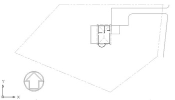
Figure 12.18: The Site12b drawing with the revised Xref of the cabin
In this exercise, you have seen how a host drawing is updated when its external reference is changed and how the appearance of objects in the Xref drawing can be controlled from the host drawing by working with the Xref layers. You also saw how you can modify objects in the Xref from the host drawing by using the In-Place Xref Edit tool. A drawing can serve as an external reference in several host drawings at the same time and have a different appearance in each one. The results of in-place Xref editing, however, must be saved back to the original drawing in order to be viewed in the Xref. So in this case, when you open Cabin12a, the front step will be missing. Also, the roof hip lines will be drawn over the room label text, as they were before they were broken in Chapter 10. In-place Xref editing is usually done only when the results are meant to be permanent changes in the original source drawing. We used it in this case only to show you how the feature works.
Applications for Xrefs
There are many different uses for external references. I will describe two common applications to illustrate their range.
Let’s suppose you are working on a project as an interior designer and a subcontractor to the lead architect. The architect can give you a drawing of a floor plan that is still undergoing changes. You load this file onto your hard disk, in a specially designated folder, and then Xref it into your drawing as a background— a drawing to be used as a reference to draw over. You can now proceed to lay out furniture, partitions, and so on, while the architect is still refining the floor plan.
At an agreed-on time, the architect will give you a revised version of the floor plan. You will overwrite the one that you have on your computer with the latest version. You can then reload the Xref into your furniture layout drawing, and the newer version of the floor plan will now be the background. In this example, the lead architect might also be sending the same versions of the floor plan to the structural and mechanical engineers and the landscape architect, all of whom are working on the project and using the architect’s floor plan as an Xref in their respective host drawings (see Figure 12.19).
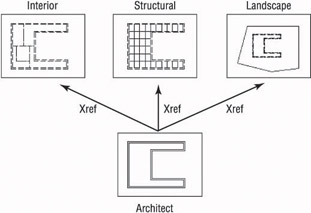
Figure 12.19: A single floor plan as an Xref to three subcontractors
Xrefs are often used when parts of a job are being done in an office where a network is in place. Suppose a project involves work on several buildings that are all on the same site. By using Xrefs, each building can be externally referenced to the site plan. This keeps the site plan drawing file from getting too large and allows the project work to be divided among different workstations, while the project manager can open the host site plan and keep track of progress on the whole project (see Figure 12.20).
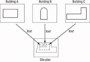
Figure 12.20: Three buildings as Xrefs to a single site plan
These two applications for setting up Xrefs in relation to a host file are applicable to almost any profession or trade using AutoCAD.
Additional Xref Features
You have seen how you can change the properties of layers in an Xref and how you can modify an Xref. A few other features of external references deserve mention.
The Xref Path
When you attach an Xref to the host drawing, AutoCAD stores the name of the Xref and its path.
| Note |
The path of a drawing file is the name of the drive, folder, and subfolder where a file is stored, followed by the name of the drawing. C: 1-My DocumentsTraining DataSite12b.dwg is the path of the current drawing file. |
Each time you open the host drawing, AutoCAD searches for any Xrefs saved with the host file and displays them in the host drawing. If the Xref drawing is moved to a new folder after the Xref has been attached, AutoCAD won’t be able to find the Xref and can’t display it. To avoid that situation, you must update the host drawing with the new path to the Xref file. We’ll go through a quick exercise to illustrate how this works.
- Close the Site12b drawing momentarily.
- Use My Computer or Windows Explorer to create a new subfolder called Xref within the Training folder you previously set up. Move Cabin12a to this folder.
- Return to AutoCAD, and open Site12b again. The Xref does not show up, but there’s a little line of information in the host drawing where the insertion point of the Xref was located. If you zoom in a couple of times, you will be able to read the information. It says “Xref C:1-My DocumentsTraining DataCabin12a.dwg.” This is the original path of the Xref.
- Press F2 to switch to the AutoCAD text screen for a moment, and note the line that says “C:1-My DocumentsTraining DataCabin12a.dwg cannot be found.” AutoCAD is unable to find the Xref because the path has changed. Press F2 again.
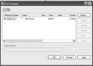
- Open the Xref Manager dialog box (choose Insert Xref Manager). In the large box where Xrefs are listed, the path is displayed for each Xref under the heading Saved Path. You can slide the scroll bar to the right to see the full path. Notice also that the Status column for this Xref reads “Not Found.”
- Click the Cabin12a Xref to highlight it.
- Next to the Xref Found At text box, click Browse. Find Cabin12a in the new Xref folder. Highlight it and click Open.
- Back in the Xref Manager dialog box, the path has been updated for Cabin12a. Click OK. Zoom Previous one or two times. The Xref is restored in your drawing.
Warning When you’re working with a lot of Xrefs, be careful where you store files that are acting as Xrefs to other files.
Binding Xrefs
On occasion, you will want to permanently attach an Xref to the host drawing. If you send your drawing files to a printing service to be plotted, including a set of Xref files can complicate things. Also, for archiving finished work, it’s better to reduce the number of files. There may also be occasions when the Xref has been revised for the last time and no longer needs to be a separate file. In all these situations, you will use the Bind command to convert an external reference into a block that will be stored permanently in the host drawing.
- Open the Xref Manager dialog box and highlight the Cabin12a Xref.
- Click the Bind button to open the Bind Xrefs dialog box.
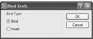
The two options in the Bind Type area have to do with how layers are treated when an Xref is bound to the host drawing. The default is Bind. It sets the Xref layers to be maintained as unique layers in the host drawing. With the Insert option, layers that have the same name in the two drawings will be combined into one layer. None of the layers in Cabin12a have the same name as any layers in Site12b. Let’s use the Insert option.
- Change the Bind Type to Insert and click OK. The Xref disappears from the list of Xrefs.
- Click OK. Your drawing looks unchanged.
- Click the cabin, and then type li. The text window shows that the cabin is now a block reference.
- Press F2 and click the Layer button on the Object Properties toolbar. The cabin’s layers have all become layers in the Site12b drawing and no longer have the Cabin12a| prefix.
- Click OK, and then choose Insert Block. In the Insert dialog box, open the Name drop-down list. Cabin12a is listed here as a block, along with the window and two door blocks that you created in Chapter 7. One or two additional blocks may be on the list. These blocks are used by the dimensions in the drawing.
- Close the drop-down list by clicking a blank portion of the dialog box. Then click Cancel to return to your drawing. The cabin is now a permanent part of the Site12b drawing. If you need to make changes to the cabin part of the drawing, you can explode it and use the Modify commands to make those changes. Or, if you’re running AutoCAD, you can use the In-Place Xref and Block Edit tools that you used previously in Chapter 7 to modify the window block and, again in this chapter, to modify the roof lines and erase the front step.
- Save this drawing as Site12c.
This has been a quick tour of the basic operations that are used to set up and control external references. There are more features and commands for working with Xrefs than I’ve covered here, but you now know enough to start working with them.
Other Features of Xrefs
What follows are a few additional operations and features that you may find useful when you delve more deeply into external references. Play around a little and see what you can do.
- Externally referenced drawings can have drawings externally referenced to them. These are called nested Xrefs. There is no practical limit to the number of levels of nested Xrefs that a drawing can have.
- You can’t explode an Xref, but you can detach it from the host. The
Detach command is a button on the Xref Manager dialog box.
- Large, complex drawings that are Xreferenced often have their insertion points coordinated in such a way that all Xrefs are attached at the 0,0 point of the host drawing. This helps keep drawings aligned properly. By default, any drawing that is Xreferenced into a host drawing uses 0,0 as its insertion point. But you can change the coordinates of the insertion point with the Base command. With the drawing you want to change current, type base and enter the coordinates for the new insertion point.
- You can limit which layers and, to some degree, which objects in a drawing are Xreferenced in the host drawing by using Indexing and Demand Loading.
- A host drawing can be Xreferenced into the drawing that has been
Xreferenced into the host. This is called an overlay and is an option in the Attach Xref dialog box. Overlays ignore nested Xreferences.
- If you freeze the layer that was current when an Xref was attached, the entire Xref is frozen. Turning off this same layer has no effect on the visibility of the Xref.
- The Unload button in the External Reference dialog box lets you deactivate Xrefs without detaching them from the host file. They stay on the list of Xrefs and can be reloaded at any time with the Reload button. This can be useful when working with complex drawings that have many Xrefs.
If You Would Like More Practice
In this chapter, you Xreferenced the cabin drawing into the site drawing, as a landscape architect who was designing the development plan for the site might have done. If you were the lead architect, you might want to Xref the landscape architect’s site plan into your cabin drawing. Try doing this.
- Open Cabin07b. Create a new layer called Xref, assign it a color number, and make it current. Freeze all layers except 0, Balcony, Roof, Steps, and Walls.
- Attach Site12a to Cabin07b as an Xref. Zoom to Extents, and then rotate the site 90. Move the Site12a Xref to a position such that the patio meets the back step in the same way that it did earlier in this chapter. Pan and zoom in and out as needed.
- Change the Site12a layers to a dark green.
- Rotate the UCS 90 around the z-axis (as you did in Chapter 8).
- Use the Plan command to position the drawing correctly, and then zoom out a little.
- Change Ltscale to 100. Your drawing should look similar to that in Figure 12.13, shown earlier in this chapter.
- Use In-Place Reference Editing to widen the patio 3' to the east, and change the radius of the driveway to 10' in the Xref.
- Do not save the changes back to the Site12a drawing file.
Are You Experienced?
Now you can
- draw a basic site plan
- use Surveyor units to lay out property lines
- attach an external reference
- control the appearance of an external reference by modifying layers
- use Visretain to save Xref layer changes
- revise a drawing that is externally referenced
- modify an Xref from the host drawing
- update an Xref path
- bind an Xref to a host file
- set up layer filters
Introduction
- Getting to Know AutoCAD
- Basic Commands to Get Started
- Setting Up a Drawing
- Gaining Drawing Strategies: Part 1
- Gaining Drawing Strategies: Part 2
- Using Layers to Organize Your Drawing
- Grouping Objects into Blocks
- Generating Elevations
- Working with Hatches and Fills
- Controlling Text in a Drawing
- Dimensioning a Drawing
- Managing External References
- Using Layouts to Set Up a Print
- Printing an AutoCAD Drawing
- Appendix A Look at Drawing in 3D
EAN: N/A
Pages: 159
