The Inter-Autonomous System/Interprovider MPLS VPN Architecture
The Inter Autonomous System Interprovider MPLS VPN Architecture
If a customer VPN has some of its sites connected to one autonomous system, but other of its sites connected to other autonomous systems, the basic MPLS VPN architecture involving a single autonomous system will clearly not be capable of providing MPLS VPN connectivity between all customer VPN sites. In this case, an extended MPLS VPN architecture known as the inter-autonomous system or multi-autonomous system MPLS VPN architecture is required.
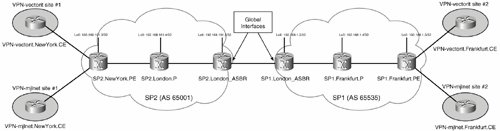
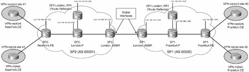
Figure 5-11 illustrates customer VPN site connectivity in an inter-autonomous system MPLS VPN architecture.
Figure 5-11. Customer VPN Site Connectivity in an Inter-Autonomous System MPLS VPN Architecture
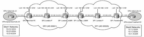
It is important to emphasize that the multiple autonomous systems shown in Figure 5-11 might be belong to a single service provider or multiple service providers. If the multiple autonomous systems over which MPLS VPN connectivity is provided belong to multiple service providers, this inter-autonomous system MPLS VPN architecture can also be called an interprovider MPLS VPN architecture.
There are a number of ways to provision an inter-autonomous system MPLS VPN architecture:
- Using VRF-to-VRF connectivity at ASBRs
- Using the advertisement of labeled VPN-IPv4 (VPNv4) between ASBRs with MP-eBGP
- Using the advertisement of labeled VPN-IPv4 (VPNv4) between route reflectors in different autonomous systems with multihop MP-eBGP
The following three sections examine each of these methods of provisioning inter-autonomous system MPLS VPN connectivity in detail.
VRF-to-VRF Connectivity at ASBRs
This model for inter-autonomous system MPLS VPN connectivity has the following characteristics:
- Each ASBR is configured as a PE router and regards its peer ASBR as a CE router.
- VRFs must be configured on ASBRs, and a separate logical or physical interface must be provisioned for each VRF.
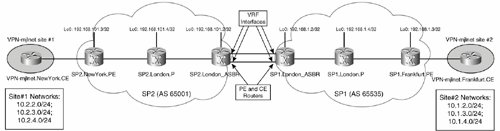
Figure 5-12 shows the configuration of an inter-autonomous system MPLS VPN architecture using VRF-to-VRF connectivity at ASBRs.
Figure 5-12. Configuration of an Inter-Autonomous System MPLS VPN Architecture Using VRF-to-VRF Connectivity at ASBRs
The advantage of configuring inter-autonomous system MPLS VPNs using VRF-to-VRF connectivity at ASBRs is the simplicity of both route/label advertisement and packet forwarding.
A major disadvantage is scalability. When provisioning inter-autonomous system MPLS VPNs using VRF-to-VRF connectivity at ASBRs, as already mentioned, VRFs must be configured on ASBRs, and a separate logical or physical interface must be configured and associated with each VRF. These limitations mean that it can often be impractical to deploy this model for inter-autonomous system MPLS VPN connectivity when there are more than a small number of VPNs (VRFs).
To understand the deployment of an inter-autonomous system MPLS VPN architecture using VRF-to-VRF connectivity at ASBRs, it is again important to examine route and label advertisement, as well as packet forwarding.
Route and Label Advertisement Between Autonomous Systems When Deploying Inter-Autonomous System MPLS VPNs VRF-to-VRF Connectivity at ASBRs
Route and label advertisement when deploying inter-autonomous system MPLS VPNs VRF-to-VRF connectivity at ASBRs is straightforward. As previously mentioned, each ASBR is configured as a PE router and treats the remote ASBR as a CE router.
Route and label advertisement when using this model for inter-autonomous system connectivity is as follows:
- PE routers advertise customer VPN site (VPN-IPv4) routes and associated VPN labels to their local ASBR (either directly or via a route reflector).
- ASBRs exchange customer VPN site routes using the configured PE-CE routing protocol. Alternatively, static VRF routes can be configured on ASBRs for connectivity to customer VPN sites in the remote autonomous system.
Note that ASBRs do not exchange VPN-IPv4 routes or labels because, as previously discussed, each ASBR acts as a PE router and regards the remote ASBR as a CE router.
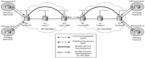
Figure 5-13 illustrates route and label advertisement when deploying inter-autonomous system MPLS VPNs VRF-to-VRF connectivity at ASBRs.
Figure 5-13. Route and Label Advertisement When Deploying Inter-Autonomous System MPLS VPNs VRF-to-VRF Connectivity at ASBRs

Example 5-10 shows the configuration of SP2.London_ASBR.
Example 5-10. Configuration of SP2.London_ASBR When Deploying Inter-Autonomous System MPLS VPNs VRF-to-VRF Connectivity at ASBRs
! ! On SP2.London_ASBR (line 1) ! ip vrf VPN-mjlnet (line 2) rd 65001:100 route-target export 65001:100 route-target import 65001:100 ! ip vrf VPN-vectorit (line 3) rd 65001:200 route-target export 65001:200 route-target import 65001:200 ! ! interface Serial1/1 encapsulation frame-relay ! interface Serial1/1.1 point-to-point (line 4) ip vrf forwarding VPN-mjlnet ip address 172.16.27.1 255.255.255.0 frame-relay interface-dlci 100 ! interface Serial1/1.2 point-to-point (line 5) ip vrf forwarding VPN-vectorit ip address 172.16.26.1 255.255.255.0 frame-relay interface-dlci 200 ! ! router bgp 65001 (line 6) no synchronization neighbor 192.168.101.3 remote-as 65001 neighbor 192.168.101.3 update-source Loopback0 no auto-summary ! address-family vpnv4 (line 7) neighbor 192.168.101.3 activate neighbor 192.168.101.3 send-community extended exit-address-family ! address-family ipv4 vrf VPN-vectorit (line 8) redistribute connected neighbor 172.16.26.2 remote-as 65535 neighbor 172.16.26.2 activate no auto-summary no synchronization exit-address-family ! address-family ipv4 vrf VPN-mjlnet (line 9) redistribute connected neighbor 172.16.27.2 remote-as 65535 neighbor 172.16.27.2 activate no auto-summary no synchronization exit-address-family ! |
As you can see in Example 5-10, the configuration of SP2.London_ASBR is much in line with standard PE router configuration.
Highlighted lines 2 and 3 define two VRFsVPN-mjlnet and VPN-vectorit.
Then, below highlighted lines 6 and 7, a BGP neighbor relationship is configured with SP2.NewYork.PE (192.168.101.3), and MP-BGP is enabled for VPN-IPv4 route exchange.
Below highlighted lines 8 and 9, BGP is configured as the PE-CE routing protocol for both VRF VPN-vectorit and VRF VPN-mjlnet, with the BGP peer (CE) for PE-CE route exchange specified as 172.16.26.2 (SP1.London_ASBR) and 172.16.27.2 (also SP1.London_ASBR), respectively. Remember that in this configuration each ASBR acts as both a PE and a CE router.
Note
It is possible to use any of the standard PE-CE routing protocols for route exchange between ASBRs, but BGP is usually preferred because it is already almost exclusively used for inter-autonomous system route exchange.
An important part of the configuration of SP2.London_ASBR can be seen below highlighted lines 4 and 5. Below these two highlighted lines, you can see the configuration of two separate Frame Relay subinterfaces, both of which connect to SP1.London_ASBR. Interface serial 1/1.1 is associated with VRF VPN-mjlnet and is used for route exchange and packet forwarding for VPN-mjlnet between ASBRs. Interface serial 1/1.2, on the other hand, is associated with VRF VPN-vectorit and is used for route exchange and packet forwarding for VPN-vectorit between ASBRs.
Highlighted lines 4 and 5 illustrate one of the scalability issues when deploying inter-autonomous system MPLS VPN VRF-to-VRF connectivity at ASBRsa separate logical or physical interface is required on each ASBR for each VRF. If you plan to configure inter-autonomous system connectivity for a large number of MPLS VPNs, the configuration of logical or physical interface can quickly get out of hand.
As shown in Example 5-11, the configuration of SP1.London_ASBR is almost identical to that of SP2.London_ASBR.
Example 5-11. Configuration of SP1.London_ASBR When Deploying Inter-Autonomous System MPLS VPNs VRF-to-VRF Connectivity at ASBRs
! ! On SP1.London_ASBR (line 1) ! ip vrf VPN-mjlnet (line 2) rd 65535:100 route-target export 65535:100 route-target import 65535:100 ! ip vrf VPN-vectorit (line 3) rd 65535:200 route-target export 65535:200 route-target import 65535:200 ! interface Serial2/1 encapsulation frame-relay ! interface Serial2/1.1 point-to-point (line 4) ip vrf forwarding VPN-mjlnet ip address 172.16.27.2 255.255.255.0 frame-relay interface-dlci 100 ! interface Serial2/1.2 point-to-point (line 5) ip vrf forwarding VPN-vectorit ip address 172.16.26.2 255.255.255.0 frame-relay interface-dlci 200 ! ! router bgp 65535 (line 6) no synchronization neighbor 192.168.1.3 remote-as 65535 neighbor 192.168.1.3 update-source Loopback0 no auto-summary ! address-family vpnv4 (line 7) neighbor 192.168.1.1 activate neighbor 192.168.1.1 send-community extended exit-address-family ! address-family ipv4 vrf VPN-vectorit (line 8) redistribute connected neighbor 172.16.26.1 remote-as 65001 neighbor 172.16.26.1 activate no auto-summary no synchronization exit-address-family ! address-family ipv4 vrf VPN-mjlnet (line 9) redistribute connected neighbor 172.16.27.1 remote-as 65001 neighbor 172.16.27.1 activate no auto-summary no synchronization exit-address-family ! |
Highlighted lines 2 and 3 show the configuration of two VRFsVPN-mjlnet and VPN-vectorit.
Highlighted lines 4 and 5 show the configuration of two Frame Relay subinterfaces associated with the VRFs.
Below highlighted lines 6 and 7, a BGP neighbor relationship is configured with SP1.Frankfurt.PE (192.168.1.3), and MP-BGP is enabled for VPN-IPv4 route exchange.
Finally, below highlighted lines 8 and 9, BGP is configured as the PE-CE routing protocol for VRF VPN-vectorit and VRF VPN-mjlnet. The BGP peer (CE) for PE-CE route exchange is specified as 172.16.26.1 (SP2.London_ASBR) and 172.16.27.1 (also SP2.London_ASBR), respectively.
In Example 5-12, an examination of the output of the show ip route vrf vrf-name command on SP2.London_ASBR and SP1.London_ASBR shows that customer VPN routes are successfully exchanged between autonomous systems.
Example 5-12. show ip route vrf Command Output on SP2.London_ASBR and SP1.London_ASBR
SP2.London_ASBR#show ip route vrf VPN-mjlnet

Routing Table: VPN-mjlnet
Codes: C - connected, S - static, I - IGRP, R - RIP, M - mobile, B - BGP
 D - EIGRP, EX - EIGRP external, O - OSPF, IA - OSPF inter area
 N1 - OSPF NSSA external type 1, N2 - OSPF NSSA external type 2
 E1 - OSPF external type 1, E2 - OSPF external type 2, E - EGP
 i - IS-IS, su - IS-IS summary, L1 - IS-IS level-1, L2 - IS-IS level-2
 ia - IS-IS inter area, * - candidate default, U - per-user static route
 o - ODR

Gateway of last resort is not set

 10.0.0.0/24 is subnetted, 9 subnets
B 10.1.3.0 [20/0] via 172.16.27.2, 00:35:44 (line 1)
B 10.2.1.0 [200/0] via 192.168.101.3, 00:50:40
B 10.1.2.0 [20/0] via 172.16.27.2, 00:35:44 (line 2)
B 10.2.2.0 [200/0] via 192.168.101.3, 00:50:40
B 10.1.1.0 [20/0] via 172.16.27.2, 00:35:44 (line 3)
B 10.2.3.0 [200/0] via 192.168.101.3, 00:50:40
B 10.2.4.0 [200/0] via 192.168.101.3, 00:50:40
B 10.1.4.0 [20/0] via 172.16.27.2, 00:35:44 (line 4)
C 172.16.27.0 is directly connected, Serial1/1.1
SP2.London_ASBR#
SP1.London_ASBR#show ip route vrf VPN-mjlnet Routing Table: VPN-mjlnet Codes: C - connected, S - static, I - IGRP, R - RIP, M - mobile, B - BGP D - EIGRP, EX - EIGRP external, O - OSPF, IA - OSPF inter area N1 - OSPF NSSA external type 1, N2 - OSPF NSSA external type 2 E1 - OSPF external type 1, E2 - OSPF external type 2, E - EGP i - IS-IS, su - IS-IS summary, L1 - IS-IS level-1, L2 - IS-IS level-2 ia - IS-IS inter area, * - candidate default, U - per-user static route o - ODR Gateway of last resort is not set 10.0.0.0/24 is subnetted, 9 subnets B 10.1.3.0 [200/0] via 192.168.1.3, 02:03:22 B 10.2.1.0 [20/0] via 172.16.27.1, 00:36:54 (line 5) B 10.1.2.0 [200/0] via 192.168.1.3, 02:03:22 B 10.2.2.0 [20/0] via 172.16.27.1, 00:36:54 (line 6) B 10.1.1.0 [200/0] via 192.168.1.3, 02:03:22 B 10.2.3.0 [20/0] via 172.16.27.1, 00:36:54 (line 7) B 10.2.4.0 [20/0] via 172.16.27.1, 00:36:54 (line 8) B 10.1.4.0 [200/0] via 192.168.1.3, 02:03:22 C 172.16.27.0 is directly connected, Serial2/1.1 SP1.London_ASBR# |
Highlighted lines 1 to 4 show the VPN-mjlnet site 2 routes on SP2.London_ASBR.
Highlighted lines 5 to 8 show the VPN-mjlnet site 1 routes on SP1.London_ASBR.
Packet Forwarding Between Autonomous Systems When Deploying Inter-Autonomous System MPLS VPNs VRF-to-VRF Connectivity at ASBRs
Example 5-13 shows the packet forwarding between VPN-mjlnet site 1 (VPN-mjlnet.NewYork.CE) and VPN-mjlnet site 2 (host 10.1.2.1) as provided by the output of the traceroute command.
Example 5-13. Packet Forwarding Between mjlnet Site 1 (VPN-mjlnet.NewYork.CE) and mjlnet Site 2 (Host 10.1.2.1)
VPN=mjlnet.NewYork.CE#traceroute 10.1.2.1 Type escape sequence to abort. Tracing the route to 10.1.2.1 1 10.2.1.2 4 msec 4 msec 0 msec (line 1) 2 192.168.102.2 [MPLS: Labels 17/26 Exp 0] 96 msec 100 msec 100 msec (line 2) 3 172.16.27.1 [AS 65001] [MPLS: Label 26 Exp 0] 36 msec 36 msec 36 msec (line 3) 4 172.16.27.2 [AS 65001] 36 msec 32 msec 32 msec (line 4) 5 192.168.2.2 [MPLS: Labels 19/23 Exp 0] 188 msec 184 msec 188 msec (line 5) 6 10.1.1.1 [AS 65001] [MPLS: Label 23 Exp 0] 120 msec 120 msec 120 msec (line 6) 7 10.1.1.2 [AS 65001] 80 msec * 120 msec (line 7) VPN-mjlnet.NewYork.CE# |
The packet is forwarded from VPN-mjlnet.NewYork.CE to SP2.NewYork.PE in highlighted line 1.
In highlighted line 2, the packet transits the connection between SP2.NewYork.PE and SP2.London.P. The two label stack here consists of an IGP label (17) and a VPN label (26).
Next, the packet crosses the link between SP2.London.P and SP2.London_ASBR. Notice that the IGP label has been popped, and only the VPN label (26) remains.
The packet then crosses the link between SP2.London_ASBR and SP1.London_ASBR in highlighted line 4. It is important to note that the packet is unlabeled as it crosses this link (no surprise thereremember it is a PE-to-CE link).
In highlighted line 5, the packet crosses the connection between SP1.London_ASBR and SP1.Frankfurt.P. Once again, the packet is prepended with a two-label stack consisting of an IGP label (19) and a VPN label (23).
The packet transits the link between SP1.Frankfurt.P and SP1.Frankfurt.PE in highlighted line 6. The IGP label has been popped, but the VPN label (23) is unchanged.
In highlighted line 7, the unlabeled packet crosses the link between SP1.Frankfurt.PE and VPN-mjlnet.Frankfurt.CE.
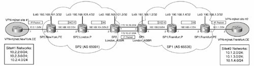
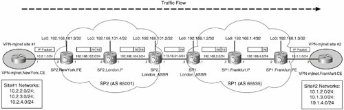
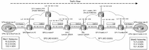
Figure 5-14 shows packet forwarding from VPN-mjlnet.NewYork.CE (mjlnet site 1) to host 10.1.2.1 (a host at mjlnet site 2).
Figure 5-14. Packet Forwarding from VPN-mjlnet.NewYork.CE (mjlnet Site 1) to Host 10.1.2.1 (a Host at mjlnet Site 2)
The output of the traceroute command in Example 5-14 shows packet forwarding between VPN-mjlnet site 2 (VPN-mjlnet.Frankfurt.CE) and VPN-mjlnet site 1 (host 10.2.2.1).
Highlighted lines 1 shows the packet as it transits the link between VPN-mjlnet.Frankfurt.CE and SP1.Frankfurt.PE.
In highlighted line 2, the packet crosses the link between SP1.Frankfurt.PE and SP1.Frankfurt.P. The label stack consists of an IGP label (18) and a VPN label (30).
Example 5-14. Packet Forwarding Between mjlnet Site 2 (VPN-mjlnet.Frankfurt.CE) and mjlnet Site 1 (Host 10.2.2.1)
VPN-mjlnet.Frankfurt.CE#traceroute 10.2.2.1 Type escape sequence to abort. Tracing the route to 10.2.2.1 1 10.1.1.1 16 msec 16 msec 16 msec (line 1) 2 192.168.4.1 [MPLS: Labels 18/30 Exp 0] 256 msec 156 msec 156 msec (line 2) 3 172.16.27.2 [AS 65535] [MPLS: Label 30 Exp 0] 88 msec 88 msec 88 msec (line 3) 4 172.16.27.1 [AS 65535] 68 msec 60 msec 64 msec (line 4) 5 192.168.104.1 [MPLS: Labels 18/20 Exp 0] 152 msec 152 msec 152 msec (line 5) 6 10.2.1.2 [AS 65535] [MPLS: Label 20 Exp 0] 144 msec 272 msec 148 msec (line 6) 7 10.2.1.1 [AS 65535] 76 msec * 80 msec (line 7) VPN-mjlnet.Frankfurt.CE# |
The packet then crosses the connection between SP1.Frankfurt.P and SP1.London_ASBR in highlighted line 3. The IGP label has been popped, but the VPN label (30) is unmodified.
The packet now passes over the link between SP1.London_ASBR and SP2.London_ASBR (see highlighted line 4). Notice that the packet is unlabeled as it crosses this link (again, it is a PE-to-CE link).
Highlighted line 5 shows the packet as it transits the connection between SP2.London_ASBR and SP2.London.P. The label stack here consists of an IGP label (18) and a VPN label (20).
In highlighted line 6, the packet transits the link between SP2.London.P and SP2.NewYork.PE. The IGP label has been popped, but the VPN label (20) in unchanged.
Finally, highlighted line 7 shows the packet as it passes over the link between SP2.NewYork.PE and VPN-mjlnet.NewYork.CE.
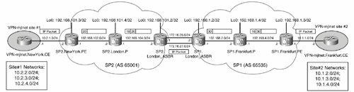
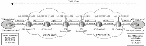
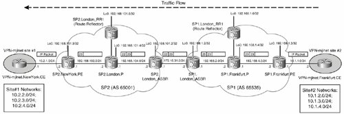
Figure 5-15 illustrates packet forwarding from VPN-mjlnet.Frankfurt.CE (VPN-mjlnet site 2) to host 10.2.2.1 (a host at VPN-mjlnet site 1).
Figure 5-15. Packet Forwarding from VPN-mjlnet.Frankfurt.CE (mjlnet Site 2) to Host 10.2.2.1 (a Host at mjlnet Site 1)
Advertisement of Labeled VPN-IPv4 (VPNv4) Between ASBRs Using MP-eBGP
A second method of provisioning inter-autonomous system MPLS VPN connectivity is to configure the advertisement of labeled customer VPN-IPv4 routes between ASBRs, as shown in Figure 5-16.
Figure 5-16. Advertisement of Customer VPN-IPv4 Routes Between ASBRs
This method of provisioning inter-autonomous system connectivity is more scalable than configuring back-to-back VRFs because there is no need to configure VRFs on the ASBRs, and there is no need to configure separate logical or physical interfaces between ASBRs.
The next two sections examine route and label advertisement between autonomous systems, as well as packet forwarding between MPLS VPN sites.
Route and Label Advertisement Between Autonomous Systems When Deploying Inter-Autonomous System MPLS VPNs Using MP-eBGP Between ASBRs
When using this method of configuring inter-autonomous system MPLS VPNs, PE routers advertise VPN-IPv4 routes to their local ASBRs. ASBRs in the different autonomous systems exchange VPN-IPv4 routes (using MP-eBGP), and then advertise these VPN-IPv4 routes to PE routers in their local autonomous system.
Note
Note that the advertisement of VPN-IPv4 routes between PE routers and their local ASBRs might not be direct. Instead, you can configure route reflectors and PE routers and ASBRs (as route reflector clients) and then exchange routes with the route reflectors.
When VPN-IPv4 routes are advertised between ASBRs, a VPN label representing each route is also advertised to the remote ASBR. These VPN labels are used to forward customer VPN packets over the ASBR-to-ASBR link.
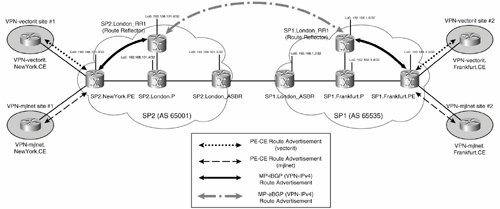
Figure 5-17 illustrates inter-autonomous system MPLS VPNs configured with the advertisement of labeled VPN-IPv4 (VPNv4) between ASBR using MP-eBGP.
Figure 5-17. Inter-Autonomous System MPLS VPNs Configured with Advertisement of Labeled VPN-IPv4 (VPNv4) Between ASBR Using MP-eBGP
In Figure 5-17, route and label advertisement from VPN-mjlnet.NewYork.CE (VPN-mjlnet site 1) and VPN-vectorit.NewYork.CE (VPN-vectorit site 1) to VPN-mjlnet.Frankfurt.CE (VPN-mjlnet site 2) and VPN-vectorit.Frankfurt.CE (VPN-vectorit site 2) is as follows:
|
1. |
VPN-mjlnet.NewYork.CE and VPN-vectorit.NewYork.CE advertise VPN-mjlnet and VPN-vectorit site 1 routes to SP2.NewYork.PE using PE-CE routing protocols. |
|
2. |
SP2.NewYork.PE advertises VPN-mjlnet and VPN-vectorit VPN site 1 (VPN-IPv4) routes and associated VPN labels to SP2.London_ASBR. |
|
3. |
SP2.London_ASBR then advertises mjlnet and vectorit site 1 (VPN-IPv4) routes and associated VPN labels to SP1.London_ASBR. The VPN labels advertised with the VPN-IPv4 routes will allow SP1.London_ASBR to forward VPN-mjlnet and VPN-vectorit user packets across the connection to SP2.London_ASBR. |
|
4. |
SP1.London_ASBR now advertises the VPN-mjlnet and VPN-vectorit site 1 (VPN-IPv4) routes and associated VPN labels (received from SP2.London_ASBR) to SP1.Frankfurt.PE. |
|
5. |
Finally, SP1.Frankfurt.PE advertises the VPN-mjlnet and VPN-vectorit site 1 routes to VPN-mjlnet.Frankfurt.CE and VPN-vectorit.Frankfurt.CE, respectively, using PE-CE routing protocols. |
Route advertisement from VPN-mjlnet.Frankfurt.CE (VPN-mjlnet site 2) and VPN-vectorit. Frankfurt.CE (VPN-vectorit site 2) to VPN-mjlnet.NewYork.CE (VPN-mjlnet site 1) and VPN-vectorit.NewYork.CE is similar:
|
1. |
VPN-mjlnet.Frankfurt.CE (VPN-mjlnet site 2) and VPN-vectorit.Frankfurt.CE (VPN-vectorit site 2) advertise VPN-mjlnet and VPN-vectorit site 2 routes to SP1.Frankfurt.PE using PE-CE routing protocols. |
|
2. |
SP1.Frankfurt.PE then advertises VPN-mjlnet and VPN-vectorit site 2 (VPN-IPv4) routes and associated VPN labels to SP1.London_ASBR. |
|
3. |
SP1.London_ASBR advertises VPN-mjlnet and VPN-vectorit site 2 (VPN-IPv4) and associated VPN labels to SP2.London_ASBR. These VPN labels will allow SP2.London_ASBR to forward mjlnet VPN packets over the link to SP1.London_ASBR. |
|
4. |
SP2.London_ASBR now advertises the VPN-mjlnet and VPN-vectorit site 2 (VPN-IPv4) routes and associated VPN labels (received from SP1.London_ASBR) to SP2.NewYork.PE. |
|
5. |
Finally, SP2.NewYork.PE advertises the VPN-mjlnet and VPN-vectorit site 2 routes to VPN-mjlnet.NewYork.CE and VPN-vectorit.NewYork.CE, respectively, using PE-CE routing protocols. |
Now that you know how route advertisement works, it is time to take a look at the configuration of ASBRs SP2.London_ASBR and SP1.London_ASBR.
Example 5-15 shows the configuration of SP2.London_ASBR when using the advertisement of labeled VPN-IPv4 (VPNv4) between ASBRs with MP-eBGP for inter-autonomous system MPLS VPN connectivity.
Example 5-15. Configuration of SP2.London_ASBR
! ! On SP2.London_ASBR (line 1) ! interface Serial1/1 ip address 172.16.31.1 255.255.255.0 mpls bgp forwarding (line 2) ! ! router ospf 100 log-adjacency-changes redistribute connected subnets (line 3) passive-interface Loopback0 network 192.168.0.0 0.0.255.255 area 0 ! router bgp 65001 no synchronization no bgp default route-target filter (line 4) neighbor 172.16.31.2 remote-as 65535 (line 5) neighbor 192.168.101.3 remote-as 65001 (line 6) neighbor 192.168.101.3 update-source Loopback0 no auto-summary ! address-family vpnv4 neighbor 172.16.31.2 activate (line 7) neighbor 172.16.31.2 send-community extended neighbor 192.168.101.3 activate (line 8) neighbor 192.168.101.3 send-community extended exit-address-family ! |
The mpls bgp forwarding command in highlighted line 2 is used to enable interface serial 1/1 (directly connected to SP2.London_ASBR) to receive MPLS packets when labels are advertised by BGP. This command is required on directly connected ASBR-to-ASBR interfaces and is automatically enabled by BGP when VPN-IPv4 route exchange is configured between ASBRs on directly connected interfaces/neighbors (so there's no need to explicitly configure the command in this example).
In highlighted line 3, the network between the SP2.London_ASR and SP1.London_ASBR (172.16.31.0/24) is redistributed into the IGP (OSPF) used within the SP2 autonomous system using the redistribute connected subnets command.
The redistribute connected subnets command is necessary because the VPN-IPv4 routes advertised from SP1.London_ASBR have a next hop of 172.16.31.2 (SP1.London_ASBR's directly connected interface address). If the network between the ASBRs (including the next-hop address of 172.16.31.2) is not redistributed into the IGP, VPN-IPv4 routes will not be installed into the VRFs on local PE routers.
Note
Another method of ensuring next-hop reachability for VPN-IPv4 routes is to use the neighbor ip-address next-hop-self command to modify the next hop of VPN-IPv4 address of VPN-IPv4 routes as they are advertised to PE routers or route reflectors within the SP2 autonomous system.
One particularly important command can be seen in highlighted line 4 (no bgp default route-target filter). This command is important because no VRFs are configured on SP2.London_ASBR. Normally, if a router receives VPN-IPv4 routes whose route targets do not match the import route targets configured within a VRF, the router drops them. In this case, of course, because no VRFs are configured on SP2.London_ASBR, it would normally drop all VPN-IPv4 routesnot what you want! The no bgp default route-target filter command ensures that VPN-IPv4 routes received by SP2.London_ASBR from SP1.London_ASBR are not dropped.
In highlighted lines 5 and 6, BGP neighbor relationships are configured with SP1.London_ASBR (172.16.31.2) and SP2.NewYork.PE (192.168.101.3).
MP-BGP (VPN-IPv4) route exchange is then enabled with SP1.London_ASBR and SP2.NewYork.PE in highlighted lines 7 and 8.
Example 5-16 shows the configuration of SP1.London_ASBR when using an advertisement of a labeled VPN-IPv4 (VPNv4) between ASBRs with MP-eBGP for inter-autonomous system MPLS VPN connectivity.
Example 5-16. Configuration of SP1.London_ASBR
! ! On SP1.London_ASBR (line 1) ! interface Serial2/1 ip address 172.16.31.2 255.255.255.0 mpls bgp forwarding (line 2) ! router isis net 49.1234.0000.0000.0001.00 is-type level-2-only metric-style wide mpls traffic-eng router-id Loopback0 mpls traffic-eng level-2 redistribute connected (line 3) ! router bgp 65535 no synchronization no bgp default route-target filter (line 4) neighbor 172.16.31.1 remote-as 65001 (line 5) neighbor 192.168.1.3 remote-as 65535 (line 6) neighbor 192.168.1.3 update-source Loopback0 no auto-summary ! address-family vpnv4 neighbor 172.16.31.1 activate (line 7) neighbor 172.16.31.1 send-community extended neighbor 192.168.1.3 activate (line 8) neighbor 192.168.1.3 send-community extended exit-address-family ! |
Highlighted line 2 shows the configuration of the mpls bgp forwarding command on the interface (serial 2/1) directly connected to SP2.London_ASBR.
In highlighted line 3, the network between SP1.London_ASBR and SP2.London_ASBR is redistributed into the IGP (IS-IS) used within the SP1 autonomous system using the redistribute connected command (this again provides next-hop reachability for MP-BGP routes).
The no bgp default route-target filter command in highlighted line 4 is used to ensure that SP1.London_ASBR does not drop VPN-IPv4 routes received from SP2.London_ASBR (there are no VRFs configured on this router).
Highlighted lines 5 and 6 shows the configuration of BGP neighbor relationships with SP2.London_ASBR (172.16.31.1) and SP1.Frankfurt.PE (192.168.1.3) highlighted lines 7 and 8 show the enabling of MP-BGP (VPN-IPv4) route exchange for these same peers.
Note
The configuration of PE routers SP2.NewYork.PE and SP1.Frankfurt.PE is standard (see the section "Configuration of PE Routers" in Chapter 4 for more information). Each PE router either peers with its local ASBR directly to exchange VPN-IPv4 routes or peers with a route reflector (which also peers with its local ASBR[s]).
As Example 5-17 demonstrates, you can see (VPN-IPv4) route advertisement between SP2.London_ASBR and SP1.London_ASBR by examining the output of the show ip bgp vpnv4 all command.
Example 5-17. Viewing Route Advertisement Between SP2.London_ASBR and SP1.London_ASBR
SP2.London_ASBR#show ip bgp vpnv4 all
BGP table version is 18, local router ID is 192.168.101.2
Status codes: s suppressed, d damped, h history, * valid, > best, i - internal,
 r RIB-failure, S Stale
Origin codes: i - IGP, e - EGP, ? - incomplete

 Network Next Hop Metric LocPrf Weight Path
Route Distinguisher: 65535:100
*> 10.1.1.0/24 172.16.31.2 0 65535 64512 I (line 1)
*> 10.1.2.0/24 172.16.31.2 0 65535 64512 i (line 2)
*> 10.1.3.0/24 172.16.31.2 0 65535 64512 i (line 3)
*> 10.1.4.0/24 172.16.31.2 0 65535 64512 i (line 4)
*>i10.2.1.0/24 192.168.101.3 0 100 0 64512 i (line 5)
*>i10.2.2.0/24 192.168.101.3 0 100 0 64512 i (line 6)
*>i10.2.3.0/24 192.168.101.3 0 100 0 64512 i (line 7)
*>i10.2.4.0/24 192.168.101.3 0 100 0 64512 i (line 8)
SP2.London_ASBR#
SP1.London_ASBR#show ip bgp vpnv4 all BGP table version is 18, local router ID is 192.168.1.2 Status codes: s suppressed, d damped, h history, * valid, > best, i - internal, r RIB-failure, S Stale Origin codes: i - IGP, e - EGP, ? - incomplete Network Next Hop Metric LocPrf Weight Path Route Distinguisher: 65535:100 *>i10.1.1.0/24 192.168.1.3 0 100 0 64512 i (line 9) *>i10.1.2.0/24 192.168.1.3 0 100 0 64512 i (line 10) *>i10.1.3.0/24 192.168.1.3 0 100 0 64512 i (line 11) *>i10.1.4.0/24 192.168.1.3 0 100 0 64512 i (line 12) *> 10.2.1.0/24 172.16.31.1 0 65001 64512 i (line 13) *> 10.2.2.0/24 172.16.31.1 0 65001 64512 i (line 14) *> 10.2.3.0/24 172.16.31.1 0 65001 64512 i (line 15) *> 10.2.4.0/24 172.16.31.1 0 65001 64512 i (line 16) SP1.London_ASBR# |
Highlighted lines 1 to 8 show the output of the show ip bgp vpnv4 all command on SP2.London_ASBR.
In highlighted lines 1 to 4, you can see VPN-mjlnet site 2 routes. Notice the next hop for these routes (172.16.31.2)these routes have been received from SP1.London_ASBR (172.16.31.2).
Then, in highlighted lines 5 to 8, you can see VPN-mjlnet site 1 routes received from SP2.NewYork.PE (192.168.101.3).
Highlighted lines 9 to 16 show the output of the show ip bgp vpnv4 all command on SP1.London_ASBR.
Highlighted lines 9 to 12 show VPN-mjlnet site 2 routes received from PE router SP1.Frankfurt.PE (192.168.1.3).
Highlighted lines 13 to 16 show the VPN-mjlnet site 1 routes received from SP2.London_ASBR (172.16.31.1).
Packet Forwarding Between Autonomous Systems When Deploying Inter-Autonomous System MPLS VPNs Using MP-eBGP Between ASBRs
Packet forwarding in an inter-autonomous system MPLS VPN can be examined using the traceroute command.
Example 5-18 demonstrates using the traceroute command to examine packet forwarding hop by hop from VPN-mjlnet site 1 (VPN-mjlnet.NewYork.CE) to VPN-mjlnet site 2 (host 10.1.2.1).
Example 5-18. Traceroute Results from mjlnet Site 1 (VPN-mjlnet.NewYork.CE) to mjlnet Site 2 (Host 10.1.2.1)
VPN-mjlnet.NewYork.CE#traceroute 10.1.2.1 Type escape sequence to abort. Tracing the route to 10.1.2.1 1 10.2.1.2 0 msec 4 msec 4 msec (line 1) 2 192.168.102.2 [MPLS: Labels 19/29 Exp 0] 336 msec 244 msec 240 msec (line 2) 3 192.168.104.2 [MPLS: Labels 16/29 Exp 0] 224 msec 224 msec 224 msec (line 3) 4 172.16.31.2 [MPLS: Label 29 Exp 0] 204 msec 204 msec 204 msec (line 4) 5 192.168.2.2 [MPLS: Labels 19/26 Exp 0] 192 msec 196 msec 192 msec (line 5) 6 10.1.1.1 [AS 65001] [MPLS: Label 26 Exp 0] 128 msec 128 msec 220 msec (line 6) 7 10.1.1.2 [AS 65001] 88 msec * 84 msec (line 7) VPN-mjlnet.NewYork.CE# |
The packet crosses the link from VPN-mjlnet.NewYork.CE to SP2.NewYork.PE in highlighted line 1.
In highlighted lines 2 and 3, the packet transits the links from SP2.NewYork.PE to SP2.London.P and SP2.London.P to SP2.London_ASBR.
Notice the label stacks in highlighted lines 2 and 3 (19/29 and 16/29). The outer label in each stack (19 and 16, respectively) is an IGP label, and inner label (29) is a VPN label. The VPN label (29) does not change as the packet is forwarded to SP2.London_ASBR.
In highlighted line 4, the packet crosses the link between SP2.London_ASBR and SP1.London_ASBR.
Take a close look at the label stack in highlighted line 4it consists of only the VPN label (29). This VPN label was advertised by SP1.London_ASBR to SP2.London_ASBR, and it corresponds to the VPN-IPv4 (VPN-mjlnet site 2) route 10.1.2.0/24. VPN label 29 is therefore included in the label stack forwarded with the packet in highlighted lines 2 and 3.
Highlighted line 5 shows the packet as it crosses the link between SP1.London_ASBR and SP1.Frankfurt.P. Notice that the VPN label has been swapped hereSP1.London_ASBR has swapped VPN label 29 for VPN label 26, and an IGP label (19) has been pushed onto the stack. The function of the IGP label is to transport the packet to the egress PE router (SP1.Frankfurt.PE), and the function of the VPN label (26) is to identify the VRF or outgoing interface on the egress PE router.
The packet then crosses the link from SP1.Frankfurt.P to (egress PE router) SP1.Frankfurt.PE in highlighted line 6. The IGP label has been popped here (because SP1.Frankfurt.PE is the penultimate hop LSR), but the VPN label (26) remains unchanged.
Finally, in highlighted line 7, the unlabeled packet transits the link from SP1.Frankfurt.PE to VPN-mjlnet.Frankfurt.CE.
Figure 5-18 shows packet forwarding from VPN-mjlnet site 1 (VPN-mjlnet.NewYork.CE) to mjlnet site 2 (host 10.1.2.1).
Figure 5-18. Packet Forwarding from VPN-mjlnet Site 1 (VPN-mjlnet.NewYork.CE) to mjlnet Site 2 (host 10.1.2.1)
Example 5-19 shows a traceroute in the opposite direction from VPN-mjlnet site 2 (VPN-mjlnet.Frankfurt.CE) to VPN-mjlnet site 1 (host 10.2.2.1).
Example 5-19. traceroute Results from mjlnet Site 2 (VPN-mjlnet.Frankfurt.CE) to mjlnet Site 1 (Host 10.2.2.1).
VPN-mjlnet.Frankfurt.CE#traceroute 10.2.2.1 Type escape sequence to abort. Tracing the route to 10.2.2.1 1 10.1.1.1 16 msec 20 msec 16 msec (line 1) 2 192.168.4.1 [MPLS: Labels 22/21 Exp 0] 212 msec 208 msec 264 msec (line 2) 3 192.168.2.1 [MPLS: Labels 17/21 Exp 0] 192 msec 192 msec 192 msec (line 3) 4 172.16.31.1 [MPLS: Label 21 Exp 0] 168 msec 168 msec 168 msec (line 4) 5 192.168.104.1 [MPLS: Labels 18/23 Exp 0] 152 msec 152 msec 152 msec (line 5) 6 10.2.1.2 [AS 65535] [MPLS: Label 23 Exp 0] 148 msec 148 msec 148 msec 7 10.2.1.1 [AS 65535] 84 msec * 80 msec VPN-mjlnet.Frankfurt.CE# |
Highlighted line 1 shows the packet as it is forwarded from VPN-mjlnet.Frankfurt.CE to SP1.Frankfurt.PE.
In highlighted lines 2 and 3, the packet is forwarded between routers SP1.Frankfurt.PE and SP1.Frankfurt.P, as well as SP1.Frankfurt.P and SP1.London_ASBR.
The outer label in the label stacks (22 and 17, respectively) in highlighted lines 2 and 3 is the IGP label used to forward the packet to SP1.London_ASBR. The inner label (21) is a VPN label and is unchanged as the packet is forwarded to SP2.London_ASBR.
In highlighted line 4, the packet is forwarded to SP2.London_ASBR.
The VPN label shown in highlighted line 4 (21) was advertised by SP2.London_ASBR to SP1.London_ASBR and corresponds to VPN-IPv4 (VPN-mjlnet site 1) route 10.2.2.0/24. SP1.London_ASBR advertised this VPN label to SP1.Frankfurt.PE along with VPN-IPv4 route 10.2.2.0/24.
In highlighted line 5, the packet is forwarded over the link between SP2.London_ASBR and SP2.London.P. Note that VPN label 21 has been swapped for VPN label 23, and an IGP label (18) has been pushed onto the label stack. The function of the IGP label is, of course, to forward the packet to the egress PE router (SP2.NewYork.PE), and the function of the VPN label is to identify the VRF or outgoing interface on the egress PE router.
Figure 5-19 illustrates packet forwarding from VPN-mjlnet site 2 (VPN-mjlnet. Frankfurt.CE) to VPN-mjlnet site 1 (host 10.2.2.1).
Figure 5-19. Packet Forwarding from mjlnet Site 2 (VPN-mjlnet.Frankfurt.CE) to mjlnet Site 1 (Host 10.2.2.1)
Advertisement of Labeled VPN-IPv4 (VPNv4) Between Route Reflectors in Separate Autonomous Systems Using Multihop MP-eBGP
A third method of provisioning inter-autonomous system MPLS VPN connectivity is to configure the advertisement of customer VPN-IPv4 routes and associated labels between route reflectors in the separate autonomous systems, as illustrated in Figure 5-20.
Figure 5-20. Deploying Inter-Autonomous System MPLS VPNs with the Advertisement of Labeled VPN-IPv4 (VPNv4) Between Route Reflectors in Separate Autonomous Systems Using Multihop MP-eBGP
The advantage of deploying inter-autonomous system MPLS VPNs with the advertisement of labeled VPN-IPv4 between route reflectors in separate autonomous systems is that it is more scalable than the other two methods of deploying inter-autonomous system MPLS VPNs. It is more scalable because the route reflectors are often out of the packet forwarding path between MPLS VPN sites and because ASBRs do not have to maintain VPN-IPv4 routes.
There are two disadvantages of deploying inter-autonomous system MPLS VPNs using this method:
- From a configuration and management perspective, it is more complex than the other two methods.
- It requires the advertisement of PE router addresses between autonomous systems, which might not be acceptable.
When discussing the deployment of inter-autonomous system MPLS VPNs with the advertisement of labeled VPN-IPv4 (VPNv4) between route reflectors in the separate autonomous systems, it is again useful to firstly discuss route and label advertisement between autonomous systems and then to discuss packet forwarding between MPLS VPN sites.
Route and Label Advertisement When Deploying Inter-Autonomous System MPLS VPNs with the Advertisement of Labeled VPN-IPv4 Between Route Reflectors in the Separate Autonomous Systems
When configuring inter-autonomous system MPLS VPNs using the advertisement of labeled VPN-IPv4 between route reflectors, it is important to ensure that the following routes are advertised:
- VPN-IPv4 routes VPN-IPv4 routes and associated VPN labels must be advertised between route reflectors in the separate autonomous systems.
- Routes to the next-hops of VPN-IPv4 routes In this model, the next-hops of the VPN-IPv4 routes are the loopback interface addresses of PE routers from which the routes are originally advertised.
Routes to the next-hops must be advertised between autonomous systems otherwise remote VPN-IPv4 routes will not be installed in the routing tables (VRFs) of PE routers.
Advertisement of VPN-IPv4 routes and routes to the next hops of VPN-IPv4 routes is discussed in the following two sections.
Advertisement of VPN-IPv4 Routes (and Associated VPN Labels)
The advertisement of VPN-IPv4 routes is straightforward:
|
1. |
CE routers advertise local site routes to their connected PE router using the PE-CE routing protocol (if one is configured). |
|
2. |
The PE routers advertise local customer VPN site (VPN-IPv4) routes to their local autonomous system route reflectors. |
|
3. |
The route reflectors in the separate autonomous system exchange customer VPN site (VPN-IPv4) routes. |
|
4. |
Route reflectors advertise remote autonomous system customer VPN site (VPN-IPv4) routes to PE routers in their local autonomous system. |
|
5. |
PE routers advertise remote customer VPN site routes to their attached CE routers using the PE-CE routing protocol (if one is configured). |
Figure 5-21 illustrates the advertisement of VPN-IPv4 routes between autonomous systems when deploying inter-autonomous system MPLS VPNs using MP-eBGP between route reflectors in separate autonomous systems.
Figure 5-21. Advertisement of VPN-IPv4 Routes Between Autonomous Systems When Deploying Inter-Autonomous System MPLS VPNs Using MP-eBGP Between Route Reflectors in Separate Autonomous Systems
Example 5-20 shows the configuration of route reflector SP2.London_RR1.
Example 5-20. Configuration of Route Reflectors SP2.London_RR1.
! ! On SP2.London_RR1 (line 1) ! router bgp 65001 no synchronization no bgp default ipv4-unicast no bgp default route-target filter (line 2) bgp cluster-id 100 neighbor 192.168.1.6 remote-as 65535 (line 3) neighbor 192.168.1.6 ebgp-multihop 255 (line 4) neighbor 192.168.1.6 update-source Loopback0 (line 5) neighbor 192.168.101.3 remote-as 65001 (line 6) neighbor 192.168.101.3 update-source Loopback0 (line 7) no auto-summary ! address-family vpnv4 neighbor 192.168.1.6 activate (line 8) neighbor 192.168.1.6 next-hop-unchanged (line 9) neighbor 192.168.1.6 send-community extended neighbor 192.168.101.3 activate (line 10) neighbor 192.168.101.3 route-reflector-client (line 11) neighbor 192.168.101.3 send-community extended no auto-summary exit-address-family ! |
In highlighted line 2, the no bgp default route-target filter command is used to ensure that VPN-IPv4 routes are not dropped by SP2.London_RR1. This command is essential because no VRFs are configured on SP2.London_RR1.
In highlighted lines 3 to 5, a BGP neighbor relationship is configured with SP1.London_RR1 (192.168.1.6). Note, in particular, the command in highlighted line 4 (neighbor ip-address ebgp-multihop ttl). This command is required because the neighbor relationship between the route reflectors in the separate autonomous systems is not formed over a direct connection but is formed over multiple network hops. You can specify the maximum number of hops between the route reflectors using the ttl argument.
Next, highlighted lines 6 and 7 show the configuration of a BGP neighbor relationship to the PE router in the local autonomous system. In this example, there is only one PE router, SP2.NewYork.PE (192.168.101.3).
In highlighted line 8, MP-BGP is enabled for the exchange of VPN-IPv4 (VPNv4) routes with SP1.London_RR1 (192.168.1.6).
Highlighted line 9 shows the configuration of the neighbor ip-address next-hop-unchanged command. By default, the IP address of the route reflector is used as the next-hop address of VPN-IPv4 routes advertised to route reflectors in separate autonomous systems (default eBGP behavior), but this is undesirable in this scenario because it would cause all customer VPN packets to be forwarded via the route reflector. The neighbor ip-address next-hop-unchanged command ensures that the original next-hop address of VPN-IPv4 routes (the route originating PE router [SP2.NewYork.PE]) is maintained when the routes are advertised. This way, customer VPN packets are forwarded directly between PE routers (rather than via route reflectors).
Highlighted lines 10 and 11 show that MP-BGP is enabled for the exchange of VPN-IPv4 with the local PE router, SP2.NewYork.PE, and SP2.NewYork.PE is configured as a route reflector client.
Notice that an MP-BGP neighbor relationship is not configured with the local ASBR (SP2.London_ASBR). This is because the ASBR is not required to exchange VPN-IPv4 routes with the remote autonomous system.
The configuration of route reflector SP1.London_RR1 (see Example 5-21) is similar to that for SP2.London_RR1.
Example 5-21. Configuration of Route Reflectors SP1.London_RR1
! ! On SP1.London_RR1 (line 1) ! router bgp 65535 no synchronization no bgp default ipv4-unicast no bgp default route-target filter (line 2) bgp cluster-id 100 neighbor 192.168.1.3 remote-as 65535 (line 3) neighbor 192.168.1.3 update-source Loopback0 (line 4) neighbor 192.168.101.6 remote-as 65001 (line 5) neighbor 192.168.101.6 ebgp-multihop 255 (line 6) neighbor 192.168.101.6 update-source Loopback0 (line 7) no auto-summary ! address-family vpnv4 neighbor 192.168.1.3 activate (line 8) neighbor 192.168.1.3 route-reflector-client (line 9) neighbor 192.168.1.3 send-community extended neighbor 192.168.101.6 activate (line 10) neighbor 192.168.101.6 next-hop-unchanged (line 11) neighbor 192.168.101.6 send-community extended no auto-summary exit-address-family ! |
The no bgp default route-target filter (highlighted line 2) is again used to ensure that SP1.London_RR1 does not drop VPN-IPv4 routes.
Highlighted lines 3 to 7 show the configuration of BGP neighbor relationships for SP1.Frankfurt.PE (192.168.1.3) and SP2.London_RR1 (192.168.101.6).
In highlighted lines 8 and 9, MP-BGP is enabled for VPN-IPv4 route exchange with SP1.Frankfurt.PE, and SP1.Frankfurt.PE is configured as a route reflector client.
In highlighted lines 10 and 11, MP-BGP is enabled for VPN-IPv4 route exchange with SP2.London_RR1, and SP1.London_RR1 is configured not to modify original VPN-IPv4 route next hops as these routes are advertised to SP2.London_RR1.
Example 5-22 shows the exchange of VPN-IPv4 routes between SP2.London_RR1 and SP1.London_RR1 as provided in the output of the show ip bgp vpnv4 all.
Example 5-22. show ip bgp vpnv4 all Command Output on SP2.London_RR1 and SP1.London_RR1
SP2.London_RR1#show ip bgp vpnv4 all
BGP table version is 19, local router ID is 192.168.101.6
Status codes: s suppressed, d damped, h history, * valid, > best, i - internal
Origin codes: i - IGP, e - EGP, ? - incomplete
 Network Next Hop Metric LocPrf Weight Path
Route Distinguisher: 65535:100
*> 10.1.1.0/24 192.168.1.3 0 65535 64512 I (line 1)
*> 10.1.2.0/24 192.168.1.3 0 65535 64512 i (line 2)
*> 10.1.3.0/24 192.168.1.3 0 65535 64512 i (line 3)
*> 10.1.4.0/24 192.168.1.3 0 65535 64512 i (line 4)
*>i10.2.1.0/24 192.168.101.3 0 100 0 64512 i (line 5)
*>i10.2.2.0/24 192.168.101.3 0 100 0 64512 i (line 6)
*>i10.2.3.0/24 192.168.101.3 0 100 0 64512 i (line 7)
*>i10.2.4.0/24 192.168.101.3 0 100 0 64512 i (line 8)
SP2.London_RR1#
SP1.London_RR1#show ip bgp vpnv4 all BGP table version is 19, local router ID is 192.168.1.6 Status codes: s suppressed, d damped, h history, * valid, > best, i - internal Origin codes: i - IGP, e - EGP, ? - incomplete Network Next Hop Metric LocPrf Weight Path Route Distinguisher: 65535:100 *>i10.1.1.0/24 192.168.1.3 0 100 0 64512 i (line 9) *>i10.1.2.0/24 192.168.1.3 0 100 0 64512 i (line 10) *>i10.1.3.0/24 192.168.1.3 0 100 0 64512 i (line 11) *>i10.1.4.0/24 192.168.1.3 0 100 0 64512 i (line 12) *> 10.2.1.0/24 192.168.101.3 0 65001 64512 i (line 13) *> 10.2.2.0/24 192.168.101.3 0 65001 64512 i (line 14) *> 10.2.3.0/24 192.168.101.3 0 65001 64512 i (line 15) *> 10.2.4.0/24 192.168.101.3 0 65001 64512 i (line 16) SP1.London_RR1# |
Highlighted lines 1 to 8 show the output of the show ip bgp vpnv4 all command on SP2.London_RR1.
Highlighted lines 1 to 4 show the VPN-IPv4 (VPN-mjlnet site 2) routes received by SP2.London_RR1 from SP1.London_RR1 (192.168.1.6).
Then, in highlighted lines 5 to 8, you can see VPN-IPv4 (VPN-mjlnet site 1) routes received by SP2.London_RR1 from SP2.NewYork.PE (192.168.101.3).
The same routes are, of course, shown in the output of the show ip bgp vpnv4 all command on SP1.London_RR1.
Highlighted lines 9 to 12 show VPN-IPv4 (VPN-mjlnet site 2) routes received from SP1.Frankfurt.PE (192.168.1.3), and highlighted lines 13 to 16 show VPN-IPv4 (VPN-mjlnet site 1) routes received from SP2.London_RR1 (192.168.101.6).
Before moving on, it is worth taking another look at the VPN-IPv4 routes advertised between route reflectors (see highlighted line 1 to 4 and 9 to 12). Notice that the next hops of these routes are not the route reflectors from which the routes were received (SP2.London_RR1 [192.168.101.6] and SP1.London_RR1 [192.168.1.6], as they normally would be), but are instead the original next hops (the PE routers that originally advertised the routes, SP2.NewYork.PE [192.168.101.3] and SP1.Frankfurt.PE [192.168.1.3]). The fact that the next hops are the original PE router addresses is because the neighbor ip-address next-hop-unchanged command is configured on each route reflector.
Advertisement of Routes to the Next Hops of VPN-IPv4 Routes (and Routes to Route Reflectors)
The advertisement of route to the next hops of the VPN-IPv4 routes, as well as routes to route reflectors is as follows:
|
1. |
The next hops of VPN-IPv4 routes (PE router loopback interface addresses), as well as routes to route reflectors, are advertised in the local autonomous system IGP to the local ASBR. |
|
2. |
Routes to next hops (local PE routers) and routes to local route reflectors are redistributed into BGP at the local ASBR. |
|
3. |
ASBRs exchange BGP routes to local next hops (PE routers) and route reflectors, as well as associated labels. These labels are used to forward packets across the ASBR-to-ASBR link. |
|
4. |
ASBRs redistribute BGP routes to remote next hops (PE routers) and route reflectors into the local IGP. This redistribution must be carefully controlled to ensure that instability in the remote autonomous system is not imported into the local autonomous system. |
|
5. |
PE routers receive IGP routes to remote next hops (PE routers), and route reflectors receive IGP routes to remote route reflectors. |
Figure 5-22 shows the advertisement of routes to next hops (PE routers) when deploying inter-autonomous system MPLS VPNs using MP-eBGP between route reflectors in separate autonomous systems.
Figure 5-22. Advertisement of Routes to Next Hops (PE Routers) Between Autonomous Systems When Deploying Inter-Autonomous System MPLS VPNs Using MP-eBGP Between Route Reflectors in Separate Autonomous Systems

Example 5-23 shows the configuration of ASBR SP2.London_ASBR.
Highlighted line 2 in Example 5-23 shows the mpls bgp forwarding command. As previously explained, this command is used to enable the interface (connected to the remote ASBR) to receive MPLS packets when labels are advertised using BGP.
Routes to next hops (PE routers) and route reflectors in the remote autonomous system are then redistributed into the local IGP (OSPF) using the redistribute command in highlighted line 3.
Example 5-23. Relevant Configuration of Route Reflectors SP2.London_ASBR
! ! On SP2.London_ASBR (line 1) ! interface Serial1/1 ip address 172.16.31.1 255.255.255.0 mpls bgp forwarding (line 2) ! router ospf 100 redistribute bgp 65001 subnets route-map filter-sp2 (line 3) passive-interface Loopback0 network 192.168.0.0 0.0.255.255 area 0 ! router bgp 65001 neighbor 172.16.31.2 remote-as 65535 (line 4) ! address-family ipv4 neighbor 172.16.31.2 activate (line 5) neighbor 172.16.31.2 route-map filter-sp2 in (line 6) neighbor 172.16.31.2 route-map filter-sp1 out (line 7) neighbor 172.16.31.2 send-label (line 8) no auto-summary no synchronization network 192.168.101.3 mask 255.255.255.255 (line 9) network 192.168.101.6 mask 255.255.255.255 (line 10) exit-address-family ! access-list 10 permit 192.168.101.6 (line 11) access-list 10 permit 192.168.101.3 (line 12) ! access-list 20 permit 192.168.1.3 (line 13) access-list 20 permit 192.168.1.6 (line 14) ! route-map filter-sp2 permit 10 (line 15) match ip address 20 (line 16) match mpls-label (line 17) ! route-map filter-sp1 permit 10 (line 18) match ip address 10 (line 19) set mpls-label (line 20) ! |
Notice that redistribute command in highlighted line 3 links to a route map called filter-sp2.
The route map itself is shown in highlighted lines 15 to 17. In highlighted line 16, IP prefixes specified in access list 20 (see highlighted lines 13 and 14) are matched, and then in highlighted line 17, the match mpls-label command is used to ensure that only if routes have an associated label will they be redistributed.
Note that access list 20 (highlighted lines 13 and 14) specifies routes to remote autonomous system next hops (SP1.Frankfurt.PE [192.168.1.3]) and route reflectors (SP1.London_RR1 [192.168.1.6]).
A BGP neighbor relationship with SP1.London_ASBR (172.16.31.2) is configured in highlighted line 4.
In highlighted line 5, SP1.London_ASBR is enabled for IPv4 route exchange, and then in highlighted line 6, the route map filter-sp2 is applied to filter routes advertised by SP1.London_ABSR2 (the route map is applied in an inbound direction).
You may notice that the route map specified in highlighted line 6 (filter-sp2) is the same one utilized in highlighted line 3 to control routes redistributed into the local IGP.
In highlighted line 7, the route map filter-sp1 is applied to filter routes advertised from SP2.London_ASBR to SP1.London_ASBR (the route map is applied in an outbound direction).
Route map filter-sp1 is configured from highlighted line 18 to 20. In highlighted line 19, IP prefixes specified in access list 10 are matched, and in highlighted line 20, the set mpls-label command is used to ensure that a label is assigned to each prefix specified in access list 10.
Access list 10 specifies routes to local autonomous system next hops (SP2.NewYork.PE [192.168.101.3]) and route reflectors (SP2.London_RR1 [192.168.101.6]).
The neighbor ip-address send-label command in highlighted line 8 is used to ensure that labels are sent with BGP routes advertised to SP1.London_ASBR.
Finally, in highlighted lines 9 and 10, routes to SP2.NewYork.PE (192.168.101.3) and SP2.London_RR1 (192.168.101.6) are redistributed into BGP using the network network-number [mask network-mask] command. These are the routes that are advertised to SP1.London_ASBR.
The configuration of SP1.London_ASBR is similar to that for SP2.London_ASBR, as you can see in Example 5-24.
Example 5-24. Relevant Configuration of Route Reflectors SP1.London_ASBR
! ! On SP1.London_ASBR (line 1) ! interface Serial2/1 ip address 172.16.31.2 255.255.255.0 mpls bgp forwarding (line 2) ! router isis net 49.1234.0000.0000.0001.00 is-type level-2-only metric-style wide mpls traffic-eng router-id Loopback0 mpls traffic-eng level-2 redistribute bgp 65535 route-map filter-sp1 (line 3) ! router bgp 65535 neighbor 172.16.31.1 remote-as 65001 (line 4) ! address-family ipv4 neighbor 172.16.31.1 activate (line 5) neighbor 172.16.31.1 route-map filter-sp1 in (line 6) neighbor 172.16.31.1 route-map filter-sp2 out (line 7) neighbor 172.16.31.1 send-label (line 8) no auto-summary no synchronization network 192.168.1.3 mask 255.255.255.255 (line 9) network 192.168.1.6 mask 255.255.255.255 (line 10) exit-address-family ! access-list 10 permit 192.168.1.3 (line 11) access-list 10 permit 192.168.1.6 (line 12) ! access-list 20 permit 192.168.101.6 (line 13) access-list 20 permit 192.168.101.3 (line 14) ! route-map filter-sp2 permit 10 (line 15) match ip address 10 (line 16) set mpls-label (line 17) ! route-map filter-sp1 permit 10 (line 18) match ip address 20 (line 19) match mpls-label (line 20) ! |
The mpls bgp forwarding command in highlighted line 2 has already been described.
The redistribute command in highlighted line 3 is again used to redistribute remote autonomous system next hop (PE router) and route reflector routes into the local IGP (IS-IS).
The redistribute command links to route map filter-sp1, which is defined in highlighted lines 18 to 20.
Route map filter-sp1 matches routes to SP2.NewYork.PE (192.168.101.3) and SP2.London_RR1 (192.168.101.6) as specified in access list 20 (see highlighted lines 13 and 14).
In highlighted line 4, a BGP neighbor relationship is configured with SP2.London_ASBR (172.16.31.1).
In highlighted lines 5 and 6, SP2.London_ASBR is enabled for IPv4 route exchange, and route map filter-sp1 is applied inbound to the connection.
Route map filter-sp1 is configured in highlighted lines 18 to 20. It matches routes to SP2.NewYork.PE and SP2.London_RR1 (defined in access list 20, see highlighted lines 13 and 14) and specifies that routes matched must have an associated label.
Highlighted lines 7 and 8 configure an outbound route map for routes advertised to SP2.London_ASBR (route map filter-sp2) and specify that a label should be sent along with each route advertised.
Route map filter-sp2 is defined in highlighted lines 15 to 17. It matches routes configured in access list 10 (routes to SP2.Frankfurt.PE [192.168.1.3] and SP2.London_RR1 [192.168.1.6]), specifies that a label must be assigned to each of these routes.
Routes to SP1.Frankfurt.PE and SP1.London_RR1 are redistributed into BGP in highlighted lines 9 and 10. These routes are advertised to SP2.London_RR1.
Note
Notice that SP2.London_ASBR and SP1.London_ASBR are configured to exchange IPv4 routes (plus associated labels) only. They are not configured to exchange VPN-IPv4 routesremember that VPN-IPv4 route exchange occurs only between route reflectors.
So that is configuration. Now it is time to verify route and label advertisement between the ASBRs using the show ip bgp and show ip bgp labels commands.
Example 5-25 shows the output of the show ip bgp and show ip bgp labels commands on SP2.London_ASBR.
Example 5-25. show ip bgp and show ip bgp labels Command Output on SP2.London_ASBR
SP2.London_ASBR#show ip bgp
BGP table version is 33, local router ID is 192.168.101.2
Status codes: s suppressed, d damped, h history, * valid, > best, i - internal,
 r RIB-failure, S Stale
Origin codes: i - IGP, e - EGP, ? - incomplete

 Network Next Hop Metric LocPrf Weight Path
*> 192.168.1.3/32 172.16.31.2 30 0 65535 I (line 1)
*> 192.168.1.6/32 172.16.31.2 30 0 65535 i (line 2)
*> 192.168.101.3/32 192.168.104.1 59 32768 i (line 3)
*> 192.168.101.6/32 192.168.104.1 113 32768 i (line 4)
SP2.London_ASBR#
SP2.London_ASBR#show ip bgp labels Network Next Hop In label/Out label 192.168.1.3/32 172.16.31.2 23/22 (line 5) 192.168.1.6/32 172.16.31.2 24/23 192.168.101.3/32 192.168.104.1 22(from LDP)/nolabel 192.168.101.6/32 192.168.104.1 20(from LDP)/nolabel SP2.London_ASBR# |
The output of the show ip bgp command on SP2.London_ASBR (highlighted lines 1 to 4) shows routes to SP1.Frankfurt.PE (192.168.1.3) and SP1.London_RR1 (192.168.1.6), as well as routes to SP2.NewYork.PE (192.168.101.3) and SP2.London_RR1 (192.168.101.6). The routes to SP2.NewYork.PE and SP2.London_RR1 were redistributed into BGP on SP2.London_ASBR from the local IGP, and the routes to SP1.Frankfurt.PE and SP1.London_RR1 were received from SP1.London_ASBR.
In the output of the show ip bgp labels command (highlighted line 5), you can see the label (22) assigned to route 192.168.1.3 (SP1.Frankfurt.PE) by SP1.London_ASBR and advertised to SP2.London_ASBR.
This label (22) is significant because it corresponds to the next hop (SP1.Frankfurt.PE) for VPN-mjlnet site 2 (VPN-IPv4) routes advertised by SP1.Frankfurt.PE to SP2.NewYork.PE via route reflectors SP1.London_RR1 and SP2.London_RR1. This label will be used to forward packets going from VPN-mjlnet site 1 to VPN-mjlnet site 2 across the link between SP2.London_ASBR to SP1.London_ASBR.
Example 5-26 shows the output of the show ip bgp and show ip bgp labels commands on SP1.London_ASBR.
Highlighted lines 1 to 4 show the output of the show ip bgp command on SP1.London_ASBR.
You can see routes to SP1.Frankfurt.PE (192.168.1.3), SP1.London_RR1 (192.168.1.6), SP2.NewYork.PE (192.168.101.3), and SP2.London_RR1 (192.168.101.6). Routes to SP1.Frankfurt.PE and SP1.London_RR1 were redistributed from the local IGP into BGP, and the routes to SP2.NewYork.PE and SP2.London_RR1 were received from SP2.London_ASBR.
Example 5-26. show ip bgp and show ip bgp labels Command Output on SP1.London_ASBR
SP1.London_ASBR#show ip bgp
BGP table version is 7, local router ID is 192.168.1.2
Status codes: s suppressed, d damped, h history, * valid, > best, i - internal,
 r RIB-failure, S Stale
Origin codes: i - IGP, e - EGP, ? - incomplete

 Network Next Hop Metric LocPrf Weight Path
*> 192.168.1.3/32 192.168.2.2 30 32768 i (line 1)
*> 192.168.1.6/32 192.168.2.2 30 32768 i (line 2)
*> 192.168.101.3/32 172.16.31.1 59 0 65001 i (line 3)
*> 192.168.101.6/32 172.16.31.1 113 0 65001 i (line 4)
SP1.London_ASBR#
SP1.London_ASBR#show ip bgp labels Network Next Hop In label/Out label 192.168.1.3/32 192.168.2.2 22(from LDP)/nolabel 192.168.1.6/32 192.168.2.2 23(from LDP)/nolabel 192.168.101.3/32 172.16.31.1 25/22 (line 5) 192.168.101.6/32 172.16.31.1 24/20 SP1.London_ASBR# |
The output of the show ip bgp labels command shows the label (22) assigned to route 192.168.101.3 (SP2.NewYork.PE) by SP2.London_ASBR and advertised to SP1.London_ASBR. Label 22 will be used to forward packets from VPN-mjlnet site 2 to VPN-mjlnet site 1 across the link from SP1.London_ASBR to SP2.London_ASBR.
Packet Forwarding When Deploying Inter-Autonomous System MPLS VPNs Using MP-eBGP Between Route Reflectors in Separate Autonomous Systems
Packet forwarding between customer sites is best illustrated by using traceroute.
In Example 5-27, the traceroute command is used to examine packet forwarding from VPN-mjlnet.NewYork.CE (VPN-mjlnet site 1) to host 10.1.4.1 (at VPN-mjlnet site 2).
Example 5-27. Packet Forwarding from VPN-mjlnet.NewYork.CE (mljnet Site 1) to Host 10.1.4.1 (at mjlnet Site 2)
VPN-mjlnet.NewYork.CE#traceroute 10.1.4.1 Type escape sequence to abort. Tracing the route to 10.1.4.1 1 10.2.1.2 4 msec 0 msec 0 msec (line 1) 2 192.168.102.2 [MPLS: Labels 23/28 Exp 0] 244 msec 244 msec 244 msec (line 2) 3 192.168.104.2 [MPLS: Labels 24/28 Exp 0] 224 msec 240 msec 224 msec (line 3) 4 172.16.31.2 [MPLS: Labels 22/28 Exp 0] 208 msec 212 msec 208 msec (line 4) 5 192.168.2.2 [MPLS: Labels 18/28 Exp 0] 192 msec 192 msec 196 msec (line 5) 6 10.1.1.1 [AS 65001] [MPLS: Label 28 Exp 0] 128 msec 128 msec 124 msec (line 6) 7 10.1.1.2 [AS 65001] 84 msec * 84 msec (line 7) VPN-mjlnet.NewYork.CE# |
Highlighted line 1 shows the packet as it is forwarded over the link between VPN-mjlnet.NewYork.CE and SP2.NewYork.PE.
In highlighted line 2, the packet crosses the link from SP2.NewYork.PE and SP2.London.P. The label stack here consists of an IGP label (23) and a VPN label (28). The VPN label was advertised along with its associated VPN-mjlnet site 2 route 10.1.4.0/24 from SP1.Frankfurt.PE via the route reflectors to SP2.NewYork.PE.
The packet then transits the link from SP2.London.P to SP2.London_ASBR in highlighted line 3. Notice that the IGP label has been swapped, but that the VPN label remains the same (28).
Highlighted line 4 shows the packet as it transits the link from SP2.London_ASBR to SP1.London_ASBR. Notice that the outer label used to forward the packet is the one advertised by SP1.London_ASBR (see Example 5-25, highlighted line 5). The VPN label (28) again remains unchanged.
In highlighted line 5, the packet is forwarded over the link from SP1.London_ASBR to SP1.Frankfurt.P. The IGP label is 18, and the VPN label is again unchanged (28).
The packet then transits the link from SP1.Frankfurt.P to SP1.Frankfurt.PE in highlighted line 6. The IGP label is popped, but the VPN label remains the same (28).
In highlighted line 7, the unlabeled packet crosses the link from SP1.Frankfurt.PE to VPN-mjlnet.Frankfurt.CE.
Figure 5-23 shows packet forwarding from VPN-mjlnet.NewYork.CE (mjlnet site 1) to host 10.1.4.1 (a host at VPN-mjlnet site 2).
Figure 5-23. Packet Forwarding from VPN-mjlnet.NewYork.CE (mjlnet Site 1) to Host 10.1.4.1 (a Host at mjlnet Site 2)
Packet forwarding from VPN-mjlnet.Frankfurt.CE (VPN-mjlnet site 2) to host 10.2.4.1 (a host at VPN-mjlnet site 1) is similar, as illustrated in Example 5-28.
Example 5-28. Packet Forwarding from VPN-mjlnet.Frankfurt.CE (mljnet Site 2) to Host 10.2.4.1 (at mjlnet Site 1)
VPN-mjlnet.Frankfurt.CE#traceroute 10.2.4.1 Type escape sequence to abort. Tracing the route to 10.2.4.1 1 10.1.1.1 16 msec 16 msec 16 msec (line 1) 2 192.168.4.1 [MPLS: Labels 23/23 Exp 0] 212 msec 212 msec 208 msec (line 2) 3 192.168.2.1 [MPLS: Labels 25/23 Exp 0] 188 msec 188 msec 188 msec (line 3) 4 172.16.31.1 [MPLS: Labels 22/23 Exp 0] 228 msec 172 msec 172 msec (line 4) 5 192.168.104.1 [MPLS: Labels 22/23 Exp 0] 152 msec 152 msec 156 msec (line 5) 6 10.2.1.2 [AS 65535] [MPLS: Label 23 Exp 0] 320 msec 148 msec 152 msec (line 6) 7 10.2.1.1 [AS 65535] 80 msec * 80 msec (line 7) VPN-mjlnet.Frankfurt.CE# |
The packet crosses the link from VPN-mjlnet.Frankfurt.CE to SP1.Frankfurt.PE in highlighted line 1.
Next, the packet is forwarded between SP1.Frankfurt.PE and SP1.Frankfurt.P (highlighted line 2). The label stack here consists of an IGP label (23) and a VPN label (23). The VPN label corresponds to VPN-mjlnet site 1 route 10.2.4.0/24 and was advertised to SP1.Frankfurt.PE by SP2.NewYork.PE via the route reflectors.
In highlighted line 3, the packet transits the link from SP1.Frankfurt.P to SP1.London_ASBR. The IGP label is swapped, but the VPN label remains the same (23).
Highlighted line 4 shows the packet as it crosses the link between SP1.London_ASBR and SP2.London_ASBR. Notice that the outer label (22) is the label advertised by SP2.London_ASBR to SP1.London_ASBR (see Example 5-26, highlighted line 5). The VPN label (23) is again unchanged.
SP2.London_ASBR forwards the packet to SP2.London.P in highlighted line 5. The outer label is an IGP label (22), and the inner (VPN) label is unchanged (23).
The packet now crosses the link from SP2.London.P to SP2.NewYork.PE (highlighted line 6). The IGP label has been popped, whereas the VPN label (23) is again unmodified.
Then, in highlighted line 7, the unlabeled packet transits the link between SP2.NewYork.PE and VPN-mjlnet.NewYork.CE.
Figure 5-24 illustrates packet forwarding from VPN-mjlnet.Frankfurt.CE (VPN-mjlnet site 2) to host 10.2.4.1 (a host at VPN-mjlnet site 1).
Figure 5-24. Packet Forwarding from VPN-mjlnet.Frankfurt.CE (mjlnet Site 2) to Host 10.2.4.1 (a Host at mjlnet Site 1)
Supporting Multicast Transport in MPLS Layer 3 VPNs |
Part I: Understanding VPN Technology
What Is a Virtual Private Network?
- What Is a Virtual Private Network?
- VPN Devices
- Deploying Site-to-Site and Remote Access VPNs: A Comparison
- Summary
- Review Questions
Part II: Site-to-Site VPNs
Designing and Deploying L2TPv3-Based Layer 2 VPNs
- Designing and Deploying L2TPv3-Based Layer 2 VPNs
- Benefits and Drawbacks of L2TPv3-Based L2VPNs
- L2TPv3 Pseudowire Operation
- Configuring and Verifying L2TPv3 Pseudowires
- Summary
- Review Questions
Designing and Implementing AToM-Based Layer 2 VPNs
- Designing and Implementing AToM-Based Layer 2 VPNs
- Benefits and Drawbacks of AToM-Based L2VPNs
- AToM Pseudowire Operation
- Deploying AToM Pseudowires
- Implementing Advanced AToM Features
- Summary
- Review Questions
Designing MPLS Layer 3 Site-to-Site VPNs
- Designing MPLS Layer 3 Site-to-Site VPNs
- Advantages and Disadvantages of MPLS Layer 3 VPNs
- MPLS Layer 3 VPNs Overview
- A Detailed Examination of MPLS Layer 3 VPNs
- Deploying MPLS Layer 3 VPNs
- Summary
- Review Questions
Advanced MPLS Layer 3 VPN Deployment Considerations
- Advanced MPLS Layer 3 VPN Deployment Considerations
- The Carriers Carrier Architecture
- The Inter-Autonomous System/Interprovider MPLS VPN Architecture
- Supporting Multicast Transport in MPLS Layer 3 VPNs
- Implementing QoS for MPLS Layer 3 VPNs
- Supporting IPv6 Traffic Transport in MPLS Layer 3 VPNs Using 6VPE
- Summary
- Review Questions
Deploying Site-to-Site IPsec VPNs
- Deploying Site-to-Site IPsec VPNs
- Advantages and Disadvantages of IPsec Site-to-Site VPNs
- IPsec: A Security Architecture for IP
- Deploying IPsec VPNs: Fundamental Considerations
- Summary
- Review Questions
Scaling and Optimizing IPsec VPNs
- Scaling and Optimizing IPsec VPNs
- Scaling IPsec Virtual Private Networks
- Ensuring High Availability in an IPsec VPN
- Designing QoS for IPsec VPNs
- MTU and Fragmentation Considerations in an IPsec VPN
- Summary
- Review Questions
Part III: Remote Access VPNs
Designing and Implementing L2TPv2 and L2TPv3 Remote Access VPNs
- Designing and Implementing L2TPv2 and L2TPv3 Remote Access VPNs
- Benefits and Drawbacks of L2TP Remote Access VPNs
- Operation of L2TP Voluntary/Client-Initiated Tunnel Mode
- Implementing L2TP Voluntary/Client-Initiated Tunnel Mode Remote Access VPNs
- Designing and Implementing L2TP Compulsory/NAS-Initiated Tunnel Mode Remote Access VPNs
- Integrating L2TP Remote Access VPNs with MPLS VPNs
- Summary
- Review Questions
Designing and Deploying IPsec Remote Access and Teleworker VPNs
- Designing and Deploying IPsec Remote Access and Teleworker VPNs
- Comparing IPsec Remote Access VPNs with Other Types of Remote Access VPNs
- Understanding IKE in an IPsec Remote Access VPN Environment
- Deploying IPsec Remote Access VPNs Using Preshared Key and Digital Signature Authentication
- Summary
- Review Questions
Designing and Building SSL Remote Access VPNs (WebVPN)
- Designing and Building SSL Remote Access VPNs (WebVPN)
- Comparing SSL VPNs to Other Types of Remote Access VPNs
- Understanding the Operation of SSL Remote Access VPNs
- Using Clientless SSL Remote Access VPNs (WebVPN) on the Cisco VPN 3000 Concentrator
- Implementing Full Network Access Using the Cisco SSL VPN Client
- Strengthening SSL Remote Access VPNs Security by Implementing Cisco Secure Desktop
- Enabling SSL VPNs (WebVPN) on Cisco IOS Devices
- Deploying SSL VPNs (WebVPN) on the ASA 5500
- Summary
- Review Questions
Part IV: Appendixes
Designing and Building SSL Remote Access VPNs (WebVPN)
- Designing and Building SSL Remote Access VPNs (WebVPN)
- Appendix A. VPLS and IPLS Layer 2 VPNs
- Understanding VPLS
- Understanding IPLS
- Summary: Comparing VPLS and IPLS
Appendix B. Answers to Review Questions
EAN: 2147483647
Pages: 124
