MPLS Layer 3 VPNs Overview
As discussed in Chapter 1, "What Is a Virtual Private Network?" VPNs are often classified as one of the following types:
- Overlay VPNs Customers and service providers do not exchange routing information. Instead, tunnels or circuits overlay the service provider network between CE devices
- Peer VPNs Customer and service providers do exchange routing information.
IP Reachability in an MPLS Layer 3 VPN
MPLS Layer 3 VPNs conform to the peer model, but unlike other implementations of the peer model, routing and forwarding information for different customers is kept in entirely separate routing and forwarding tables called VPN routing and forwarding tables (VRF). Figure 4-2 illustrates the VRFs used to separate customer routing and forwarding information.
Figure 4-2. VRFs Separate Customer Routing and Forwarding Information
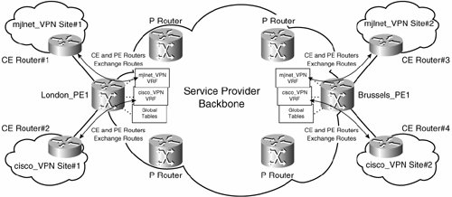
As you can see in Figure 4-2, there are two customers (VPNs), mjlnet_VPN and cisco_VPN. CE routers at mjlnet_VPN and cisco_VPN sites connect to PE routers London_PE1 and Brussels_PE1. PE routers London_PE1 and Brussels_PE1 exchange routing information with the CE routers (assuming that static routes are not used) and maintain routing and forwarding information relating to mjlnet_VPN and cisco_VPN in separate VRFs. PE routers also maintain global routing and forwarding tables, which contain routes to other PE and Provider (P) routers, as well as any Internet routes. P routers are connected only to PE routers and other P routers, not to customer sites.
Note that in an MPLS Layer 3 VPN, CE routers do not peer with each other and directly exchange routing information as they would when, for example, directly connected to each other via PVCs in a Frame Relay overlay VPN.
So, PE and CE routers are routing peers, and PE routers maintain customer VPN routing and forwarding information in VRFs. But, how is customer VPN routing information exchanged across the service provider backbone between PE routers? The answer is that the PE routers exchange customer VPN routes (and associated VPN labels [more on this later]) with each other using Multiprotocol Extensions to BGP (MP-BGP, RFC2858/draft-ietf-idr-rfc2858bis), as illustrated in Figure 4-3.
Figure 4-3. PE Routers Exchange Customer VPN Routes and Associated VPN Labels Using MP-BGP
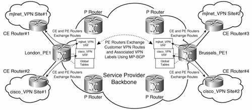
In Figure 4-3, PE routers London_PE1 and Brussels_PE1 exchange customer VPN routes using MP-BGP. These routes are then inserted into the appropriate customer VRF: mjlnet_VPN routes are inserted into the mjlnet_VPN VRF, and cisco_VPN routes are inserted into the cisco_VPN VRF.
The routing paradigm used in MPLS Layer 3 VPNs can be summarized as follows:
- CE and PE routers exchange customer VPN routes using routing protocols such as RIPv2, EIGRP, OSPF, or eBGP. Alternatively, static routes can be used for IP reachability.
- PE routers exchange customer VPN routes (and associated VPN labels) using MP-BGP. Note that route reflectors are often used in larger deployments. See Figure 3-37 in Chapter 3, "Designing and Implementing AToM-Based Layer 2 VPNs," for the exact format of the MPLS label (MPLS shim header).
- Different customer VPN routes are stored in separate VRFs.
So, for example, in Figure 4-3, the CE router at mjlnet_VPN site 1 sends local site routes to its attached PE router, London_PE1, using RIPv2, EIGRP, OSPF, or EBGP. These routes are inserted into the mjlnet_VPN VRF.
London_PE1 then advertises the mjlnet_VPN site 1 routes (and associated VPN labels) to Brussels_PE1 using MP-BGP. Brussels_PE1 inserts these routes into its mjlnet_VPN VRF.
Finally, Brussels_PE1 sends the mjlnet_VPN site 1 routes to the CE router at the mjlnet_VPN site 2 using the CE-PE routing protocol. The CE router at mjlnet_VPN site 2 now has IP reachability to the mjlnet_VPN site 1. IP reachability from mjlnet_VPN site 1 to mjlnet_VPN site 2 is accomplished in a similar fashion.
The CE router at mjlnet_VPN site 2 sends mjlnet_VPN site 2 routes to its attached PE router, Brussels_PE1. Brussels_PE1 inserts these routes into the mjlnet_VPN VRF. Brussels_PE1 now advertises the mjlnet_VPN site 2 routes (along with associated VPN labels) to London_PE1 using MP-BGP. London_PE1 inserts these routes into its mjlnet_VPN VRF.
Finally, London_PE1 sends the mjlnet_VPN site 2 routes to the CE router at mjlnet_VPN site 1 using the PE-CE routing protocol. The CE router at mjlnet_VPN site 2 now has IP reachability to mjlnet_VPN site 2.
Routes for the cisco_VPN are similarly advertised between CE routers across the service provider backbone: cisco_VPN CE routers sends routes to attached PE routers, and PE routers insert these routes into the cisco_VPN VRF; PE routers advertise cisco_VPN routes to each other using MP-BGP, and these routes are inserted into the cisco_VPN VRF; PE routers send routes to the remote cisco_VPN site to their attached cisco_VPN CE router using the PE-CE routing protocol.
So, that is route exchange and IP reachability, but what about user packet forwarding?
User Packet Forwarding Between MPLS Layer 3 VPN Sites
When a PE router receives a user packet from an attached CE router, it examines the destination address in the packet's IP header. The PE router will find a longest-match route in the customer VRF corresponding to the interface on which the user packet was received.
The VPN label associated with the route in the VRF will then be prepended to the user packet, and the packet will then be further encapsulated with another MPLS label (in a service provider backbone where MPLS is enabled), IP or GRE, L2TPv3, or IP/IPsec, and then forwarded across the backbone to the PE router that is attached to the VPN site to which the user packet is destined. This chapter assumes that the service provider backbone is MPLS enabled.
Figure 4-4 illustrates user packet forwarding between MPLS Layer 3 VPN sites.
Figure 4-4. User Packet Forwarding Between MPLS Layer 3 Sites
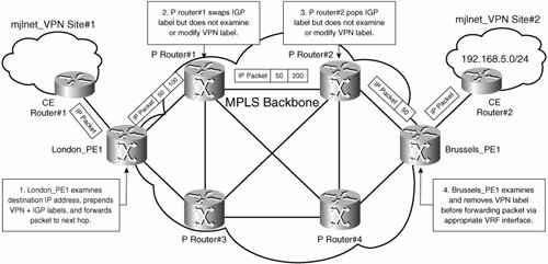
In Figure 4-4, a user packet is sent from mjlnet_VPN site 1 to network 192.168.5.0/24 at mjlnet_VPN site 2. When the user packet arrives at London_PE1 from CE Router #1, the PE router examines the destination IP address, finds the longest match in its mjlnet_VPN VRF (a VPN route to 192.168.5.0/24), and prepends the VPN label corresponding to the route 192.168.5.0/24 to the user packet. In this example, the VPN label has a value of 50.
It is important to reiterate where the VPN route and label came from. If you refer back to Figure 4-3, you can see that the PE routers exchange customer VPN routes and associated VPN labels. In this case, Brussels_PE1 has advertised a VPN route to 192.168.5.0/24 with VPN label 50 (a label value selected by Brussels_PE1) to London_PE1. The VPN label indicates the VRF or outgoing VRF interface on Brussels_PE1.
So, the user packet has arrived at London_PE1, London_PE1 has examined the destination IP address, found the longest-matching VPN route in the appropriate VRF (192.168.5.0/24 in mjlnet_VPN VRF in this example), and prepended the VPN label corresponding to this route (label 50 in this example).
The PE router must now encapsulate the packet with an additional MPLS label (if the service provider backbone is MPLS enabled), IP or GRE, L2TPv3, or IP/IPsec. In this example, the service provider backbone is MPLS enabled, and so London_PE1 prepends an additional MPLS label. The purpose of this additional (IGP) MPLS label or encapsulation is to ensure that the user packet can get from London_PE1 to Brussels_PE1. Remember that the already-prepended VPN label indicates the VRF or outgoing VRF interface on Brussels_PE1, but none of the P routers between PE routers London_PE1 and Brussels_PE1 has any knowledge of VPN labels. The IGP label, on the other hand, corresponds to a Label Switched Path (LSP) between PE routers London_PE1 and Brussels_PE1. In this case, the Label Distribution Protocol (LDP) is being used to signal IGP labels, and so the IGP label corresponds to the IGP route to Brussels_PE1 and in this example has a value of 100. This IGP label (100) is prepended to the user packet in addition to the VPN label (50).
Note
PE and P routers can signal (advertise) IGP labels to each other using the LDP, the Tag Distribution Protocol (TDP), or the Resource Reservation Protocol (RSVP). LDP- and TDP-signaled IGP labels correspond to IGP routes, and RSVP-signaled IGP labels correspond to traffic-engineered tunnels through the MPLS backbone network.
TDP is a legacy (Cisco proprietary) protocol, and its use is now deprecated in favor of LDP.
London_PE1 now forwards the labeled user packet to P Router #1. P Router #1 swaps IGP label 100 for IGP label 200 (which also corresponds to an IGP route to Brussels_PE1) and forwards the labeled packet to P Router #2. Note that P Router #1 does not examine or modify the VPN label (50).
P Router #2, being the penultimate hop in the LSP to Brussels_PE1, pops (removes) the IGP label (200) and forwards the labeled user packet to Brussels_PE1. At this stage, the label stack consists only of the VPN label (50).
Brussels_PE1 receives the labeled packet, pops the label stack (consisting of the VPN label), and based on the VPN label, either looks in the appropriate VRF for a route (in this case, mjlnet_VPN VRF) or just forwards the unlabeled user packet out of the VRF interface. The CE router at mjlnet_VPN site 2 now receives the unlabeled user packet and forwards it according to the regular IP routing paradigm.
A Detailed Examination of MPLS Layer 3 VPNs |
Part I: Understanding VPN Technology
What Is a Virtual Private Network?
- What Is a Virtual Private Network?
- VPN Devices
- Deploying Site-to-Site and Remote Access VPNs: A Comparison
- Summary
- Review Questions
Part II: Site-to-Site VPNs
Designing and Deploying L2TPv3-Based Layer 2 VPNs
- Designing and Deploying L2TPv3-Based Layer 2 VPNs
- Benefits and Drawbacks of L2TPv3-Based L2VPNs
- L2TPv3 Pseudowire Operation
- Configuring and Verifying L2TPv3 Pseudowires
- Summary
- Review Questions
Designing and Implementing AToM-Based Layer 2 VPNs
- Designing and Implementing AToM-Based Layer 2 VPNs
- Benefits and Drawbacks of AToM-Based L2VPNs
- AToM Pseudowire Operation
- Deploying AToM Pseudowires
- Implementing Advanced AToM Features
- Summary
- Review Questions
Designing MPLS Layer 3 Site-to-Site VPNs
- Designing MPLS Layer 3 Site-to-Site VPNs
- Advantages and Disadvantages of MPLS Layer 3 VPNs
- MPLS Layer 3 VPNs Overview
- A Detailed Examination of MPLS Layer 3 VPNs
- Deploying MPLS Layer 3 VPNs
- Summary
- Review Questions
Advanced MPLS Layer 3 VPN Deployment Considerations
- Advanced MPLS Layer 3 VPN Deployment Considerations
- The Carriers Carrier Architecture
- The Inter-Autonomous System/Interprovider MPLS VPN Architecture
- Supporting Multicast Transport in MPLS Layer 3 VPNs
- Implementing QoS for MPLS Layer 3 VPNs
- Supporting IPv6 Traffic Transport in MPLS Layer 3 VPNs Using 6VPE
- Summary
- Review Questions
Deploying Site-to-Site IPsec VPNs
- Deploying Site-to-Site IPsec VPNs
- Advantages and Disadvantages of IPsec Site-to-Site VPNs
- IPsec: A Security Architecture for IP
- Deploying IPsec VPNs: Fundamental Considerations
- Summary
- Review Questions
Scaling and Optimizing IPsec VPNs
- Scaling and Optimizing IPsec VPNs
- Scaling IPsec Virtual Private Networks
- Ensuring High Availability in an IPsec VPN
- Designing QoS for IPsec VPNs
- MTU and Fragmentation Considerations in an IPsec VPN
- Summary
- Review Questions
Part III: Remote Access VPNs
Designing and Implementing L2TPv2 and L2TPv3 Remote Access VPNs
- Designing and Implementing L2TPv2 and L2TPv3 Remote Access VPNs
- Benefits and Drawbacks of L2TP Remote Access VPNs
- Operation of L2TP Voluntary/Client-Initiated Tunnel Mode
- Implementing L2TP Voluntary/Client-Initiated Tunnel Mode Remote Access VPNs
- Designing and Implementing L2TP Compulsory/NAS-Initiated Tunnel Mode Remote Access VPNs
- Integrating L2TP Remote Access VPNs with MPLS VPNs
- Summary
- Review Questions
Designing and Deploying IPsec Remote Access and Teleworker VPNs
- Designing and Deploying IPsec Remote Access and Teleworker VPNs
- Comparing IPsec Remote Access VPNs with Other Types of Remote Access VPNs
- Understanding IKE in an IPsec Remote Access VPN Environment
- Deploying IPsec Remote Access VPNs Using Preshared Key and Digital Signature Authentication
- Summary
- Review Questions
Designing and Building SSL Remote Access VPNs (WebVPN)
- Designing and Building SSL Remote Access VPNs (WebVPN)
- Comparing SSL VPNs to Other Types of Remote Access VPNs
- Understanding the Operation of SSL Remote Access VPNs
- Using Clientless SSL Remote Access VPNs (WebVPN) on the Cisco VPN 3000 Concentrator
- Implementing Full Network Access Using the Cisco SSL VPN Client
- Strengthening SSL Remote Access VPNs Security by Implementing Cisco Secure Desktop
- Enabling SSL VPNs (WebVPN) on Cisco IOS Devices
- Deploying SSL VPNs (WebVPN) on the ASA 5500
- Summary
- Review Questions
Part IV: Appendixes
Designing and Building SSL Remote Access VPNs (WebVPN)
- Designing and Building SSL Remote Access VPNs (WebVPN)
- Appendix A. VPLS and IPLS Layer 2 VPNs
- Understanding VPLS
- Understanding IPLS
- Summary: Comparing VPLS and IPLS
Appendix B. Answers to Review Questions
EAN: 2147483647
Pages: 124
