Understanding VPLS
As previously mentioned, a VPLS is a multipoint emulated LAN service provisioned over a MAN or WAN. A VPLS is an Ethernet broadcast domain, and is fully capable of forwarding Ethernet traffic based on learned MAC addresses.
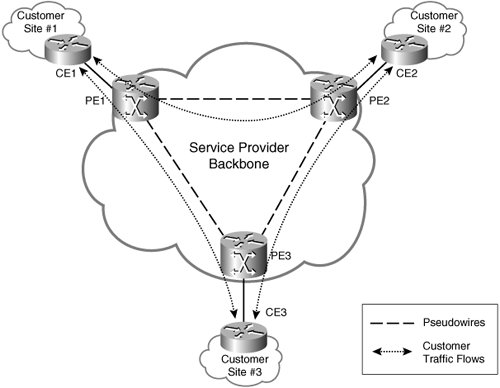
Figure A-1 illustrates a VPLS. This figure illustrates a single VPLS. As you can see, Provider Edge (PE) devices PE1, PE2, and PE3 are connected via pseudowires. The PE devices are also connected to Customer Edge (CE) devices CE1, CE2, and CE3. Customer traffic flows between CE devices CE1, CE2, and CE3.
Figure A-1. A VPLS
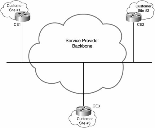
The VPLS in Figure A-1 appears to the customer as a single broadcast domain, as shown in Figure A-2.
Figure A-2. A VPLS Is a Single-Broadcast Domain
Note
Although a single VPLS is illustrated in Figure A-1, PE devices can support multiple separate VPLS (customer broadcast domains).
If a pair of PEs is in more than one VPLS, more than one pseudowire is required between that pair of PEs (one pseudowire per VPLS). In this case, the pseudowires can be carried over the same tunnel (either a tunnel Label Switched Path [LSP] or other tunnel type).
For more information on MPLS- and L2TPv3-based pseudowires, see Chapter 3, "Designing and Implementing AToM-Based Layer 2 VPNs (L2VPN)," and Chapter 2, "Designing and Deploying L2TPv3-Based Layer 2 VPNs (L2VPN)," respectively.
A VPLS can provide the following connectivity models:
- Connectivity between CE routers
- Connectivity between CE Ethernet switches
The VPLS in Figure A-1 provides connectivity between CE routers.
A VPLS provides the usual connectivity that would be expected in a LAN segment, including forwarding of unicast traffic, multicast traffic, and broadcast traffic.
Each PE device operates in a similar manner to an Ethernet switch and is capable of dynamically learning (and aging) MAC addresses and forwarding traffic based on those learned MAC addresses. Pseudowires between PE devices are treated as logical ports, and so a PE device will forward Ethernet traffic between attachment circuits (connected to CE routers/switches) and pseudowires (connected to other PE devices) in a similar manner to that which a regular Ethernet switch uses to forward traffic between ports.
Note
Forwarding of multicast traffic can be optimized in a VPLS by utilizing mechanisms such as Internet Group Multicast Protocol (IGMP) and Protocol Independent Multicast (PIM) snooping on PE devices.
Ensuring a Loop-Free Topology in a VPLS
The PEs in a VPLS can have a full mesh of pseudowires between themselves (see Figure A-1). As previously mentioned, these pseudowires function as logical ports as far as the learning of MAC addresses and forwarding of Ethernet traffic is concerned.
If a full mesh of pseudowires is maintained between PEs, the Spanning Tree Protocol (STP) is not required on the PEs. In this case, the PEs perform split-horizon forwardingEthernet traffic received on one pseudowire from one PE is not forwarded on another pseudowire to another PE.
Figure A-3 illustrates split-horizon forwarding in a VPLS.
Figure A-3. Split-Horizon Forwarding in a VPLS
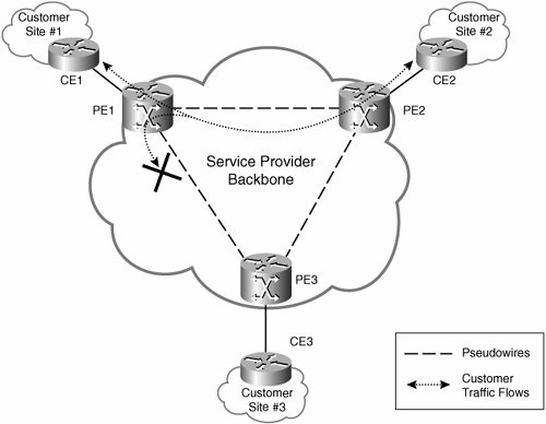
As you can see in Figure A-3, Ethernet traffic received by PE1 from PE2 is not then sent over the pseudowire to PE3.
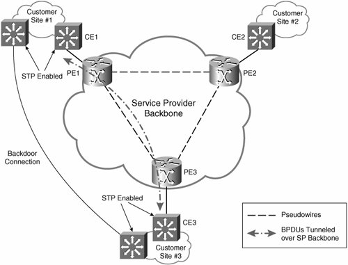
Customers may still run STP to prevent loops if they maintain "backdoor" connections (connections not via the VPLS) between sites. In this case, Bridge Protocol Data Units (BPDU) are tunneled over the service provider network without being examined (and acted upon) by PE devices.
Figure A-4 illustrates a backdoor connection between customer sites and the corresponding STP configuration.
Figure A-4. Backdoor Connection and Corresponding STP Configuration
Frame Forwarding over a VPLS
Ethernet frames are sent over pseudowires between PEs in a VPLS as described in Chapter 3.
Although Figure A-1 shows CE devices connected to dedicated ports on PE devices, it is possible that more than one CE device (different customers) might be connected to a single physical port on a PE device. In this case, an identifier such as a VLAN tag may be used to separate traffic for different customer VPLSs on that port.
When a PE receives an Ethernet frame from a customer, any identifiers on Ethernet frames (such as a VLAN tag) used to identify a particular VPLS are removed before the frame is forwarded over a pseudowire to another PE. The egress PE may prepend an identifier back onto the frame before forwarding the frame.
If a PE receives an Ethernet frame from a customer with an identifier that does not identify a VPLS (for example, when VLAN tagging is used by a customer, and this tagging is not used by the PE device to distinguish between VPLSs), this identifier is not removed before the frame is forwarded over a pseudowire to another PE.
VPLS MAC Address Learning
MAC addresses are learned and associated with customer-connected ports and PE-connected pseudowires. Mappings of customer MAC addresses to pseudowires are stored within a Forwarding Information Base (FIB) on PEs. Mappings for different VPLSs are stored in separate FIBs.
There are two methods of MAC address learning used in a VPLS:
- Unqualified learning
- Qualified learning
When using unqualified learning, a single VPLS handles all the VLANs belonging to a customer. In this case, there must be no overlap between MAC addresses among customer VLANs (there is a single MAC address space). If an overlap occurs, traffic might be forwarded incorrectly.
Unqualified learning can be used when connectivity to a customer is on a nonmultiplexed port (there is only one customer per physical port), and the customer might be forwarding traffic for multiple VLANs on the physical port.
When using qualified learning, each customer VLAN is mapped to a separate VPLS and therefore is mapped to its own broadcast domain and MAC address space. If an overlap occurs between MAC addresses in different VLANs when using qualified learning, it will not affect traffic forwarding because each VPLS (and VLAN) has its own FIB.
Hierarchical VPLS (H-VPLS) Deployments
As previously discussed in this appendix, a full mesh of pseudowires can be provisioned between PEs in a VPLS. This means that the total number of pseudowires required per VPLS is n(n - 1)/2 (where n is the number of PE devices). The amount of signaling required to set up and maintain this number of pseudowires, as well as the amount of packet replication required, may impact the scalability of a VPLS deployment (as the number of PE devices and pseudowires grows).
To improve the scalability of VPLS deployments, a hierarchical architecture may be used (see Figure A-5). In Figure A-5, an additional level of hierarchy has been added to the basic VPLS architecture (compare to Figure A-1). The functionality of the PE device can now be divided between Network-facing PEs (N-PEs/PE-rs [routing- and bridging-capable PEs]) and User (customer)-facing PEs (U-PEs) or MTU-s (multitenant unit bridging-capable devices).
Figure A-5. Hierarchical VPLS Architecture
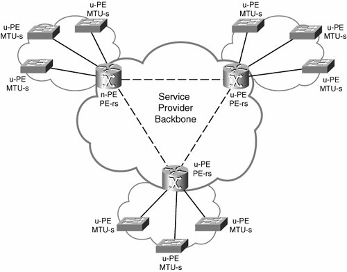
In a hierarchical VPLS architecture, a full mesh of pseudowires can be maintained between N-PEs/PE-rs, and connectivity between U-PEs/MTU-s is provided via either pseudowires or Q-in-Q (802.1Q in 802.1Q) encapsulation. Pseudowires between PE-rs and MTU-s terminate in virtual switch instances (VSI; called virtual forwarding instances [VFI] in Cisco terminology).
Part I: Understanding VPN Technology
What Is a Virtual Private Network?
- What Is a Virtual Private Network?
- VPN Devices
- Deploying Site-to-Site and Remote Access VPNs: A Comparison
- Summary
- Review Questions
Part II: Site-to-Site VPNs
Designing and Deploying L2TPv3-Based Layer 2 VPNs
- Designing and Deploying L2TPv3-Based Layer 2 VPNs
- Benefits and Drawbacks of L2TPv3-Based L2VPNs
- L2TPv3 Pseudowire Operation
- Configuring and Verifying L2TPv3 Pseudowires
- Summary
- Review Questions
Designing and Implementing AToM-Based Layer 2 VPNs
- Designing and Implementing AToM-Based Layer 2 VPNs
- Benefits and Drawbacks of AToM-Based L2VPNs
- AToM Pseudowire Operation
- Deploying AToM Pseudowires
- Implementing Advanced AToM Features
- Summary
- Review Questions
Designing MPLS Layer 3 Site-to-Site VPNs
- Designing MPLS Layer 3 Site-to-Site VPNs
- Advantages and Disadvantages of MPLS Layer 3 VPNs
- MPLS Layer 3 VPNs Overview
- A Detailed Examination of MPLS Layer 3 VPNs
- Deploying MPLS Layer 3 VPNs
- Summary
- Review Questions
Advanced MPLS Layer 3 VPN Deployment Considerations
- Advanced MPLS Layer 3 VPN Deployment Considerations
- The Carriers Carrier Architecture
- The Inter-Autonomous System/Interprovider MPLS VPN Architecture
- Supporting Multicast Transport in MPLS Layer 3 VPNs
- Implementing QoS for MPLS Layer 3 VPNs
- Supporting IPv6 Traffic Transport in MPLS Layer 3 VPNs Using 6VPE
- Summary
- Review Questions
Deploying Site-to-Site IPsec VPNs
- Deploying Site-to-Site IPsec VPNs
- Advantages and Disadvantages of IPsec Site-to-Site VPNs
- IPsec: A Security Architecture for IP
- Deploying IPsec VPNs: Fundamental Considerations
- Summary
- Review Questions
Scaling and Optimizing IPsec VPNs
- Scaling and Optimizing IPsec VPNs
- Scaling IPsec Virtual Private Networks
- Ensuring High Availability in an IPsec VPN
- Designing QoS for IPsec VPNs
- MTU and Fragmentation Considerations in an IPsec VPN
- Summary
- Review Questions
Part III: Remote Access VPNs
Designing and Implementing L2TPv2 and L2TPv3 Remote Access VPNs
- Designing and Implementing L2TPv2 and L2TPv3 Remote Access VPNs
- Benefits and Drawbacks of L2TP Remote Access VPNs
- Operation of L2TP Voluntary/Client-Initiated Tunnel Mode
- Implementing L2TP Voluntary/Client-Initiated Tunnel Mode Remote Access VPNs
- Designing and Implementing L2TP Compulsory/NAS-Initiated Tunnel Mode Remote Access VPNs
- Integrating L2TP Remote Access VPNs with MPLS VPNs
- Summary
- Review Questions
Designing and Deploying IPsec Remote Access and Teleworker VPNs
- Designing and Deploying IPsec Remote Access and Teleworker VPNs
- Comparing IPsec Remote Access VPNs with Other Types of Remote Access VPNs
- Understanding IKE in an IPsec Remote Access VPN Environment
- Deploying IPsec Remote Access VPNs Using Preshared Key and Digital Signature Authentication
- Summary
- Review Questions
Designing and Building SSL Remote Access VPNs (WebVPN)
- Designing and Building SSL Remote Access VPNs (WebVPN)
- Comparing SSL VPNs to Other Types of Remote Access VPNs
- Understanding the Operation of SSL Remote Access VPNs
- Using Clientless SSL Remote Access VPNs (WebVPN) on the Cisco VPN 3000 Concentrator
- Implementing Full Network Access Using the Cisco SSL VPN Client
- Strengthening SSL Remote Access VPNs Security by Implementing Cisco Secure Desktop
- Enabling SSL VPNs (WebVPN) on Cisco IOS Devices
- Deploying SSL VPNs (WebVPN) on the ASA 5500
- Summary
- Review Questions
Part IV: Appendixes
Designing and Building SSL Remote Access VPNs (WebVPN)
- Designing and Building SSL Remote Access VPNs (WebVPN)
- Appendix A. VPLS and IPLS Layer 2 VPNs
- Understanding VPLS
- Understanding IPLS
- Summary: Comparing VPLS and IPLS
Appendix B. Answers to Review Questions
EAN: 2147483647
Pages: 124
