Implementing L2TP Voluntary/Client-Initiated Tunnel Mode Remote Access VPNs
Implementing L2TP Voluntary Client Initiated Tunnel Mode Remote Access VPNs
As previously mentioned, voluntary (client-initiated) tunnel mode can be used to implement remote access VPNs between client workstations/routers and a VPN gateway.
It is important to review the function of each element and protocol when using L2TP/IPsec to tunnel traffic between remote access client workstations and a VPN gateway:
- IPsec IPsec is used to protect the L2TP tunnel.
Two types of (IKE) authentication are used with IPsec (in an L2TP voluntary/client-initiated tunnel mode deployment):
- Preshared key (PSK) authenticationA PSK is an alphanumeric string which must be identical on both the remote access VPN client workstation and the VPN gateway.
- Digital signature (digital certificate) authenticationIn this case, the remote access client workstation/router and the VPN gateway must both be enrolled with (both possess a digital certificate from) the same certificate authority (CA) or CA hierarchy.
- L2TP L2TP is used to tunnel PPP frames between the remote access client workstation/router and the VPN gateway.
- PPP PPP frames carry IP or other network protocols between the remote access VPN client workstation/router and the VPN gateway. Protocols such as the CHAP or the Microsoft Challenge Handshake Protocol versions 1 and 2 (MS-CHAPv1 and v2) can also be used during PPP negotiation for user authentication.
Reading the preceding list, you will have noticed that two components are used for authentication when using L2TP/IPsec: IPsec and PPP. As previously discussed, the difference is that IPsec (IKE) authentication is used to authenticate the remote access client workstation, and PPP authentication is used to authenticate the user of the remote access client workstation. Authentication of the user of a remote access client workstation is important; otherwise, anyone with access to the workstation (including someone who has stolen the workstation) could authenticate himself with the VPN gateway.
The following two sections discuss the configuration of L2TP/IPsec remote access VPNs with PSK authentication and with digital signature authentication.
Configuring PSK Authentication for L2TP/IPsec Voluntary Tunnel Mode VPNs
The advantage of configuring PSK authentication with L2TP/IPsec is that it is relatively simple when compared to the configuration of digital signature (digital certificate) authentication with L2TP/IPsec. The disadvantage of PSK authentication is that it is not as secure as digital signature authentication.
There are two parts to the configuration of PSK authentication with L2TP/Ipsec:
- Configuration of the VPN gateway
- Configuration of the remote access VPN clients
The sections that follow cover these aspects of configuring PSK authentication with L2TP/IPsec.
Configuring a Cisco VPN 3000 Concentrator as an L2TP/IPsec VPN Gateway for PSK Authentication
The configuration of a Cisco VPN 3000 concentrator as an L2TP/IPsec VPN gateway consists of a number of steps:
|
Step 1. |
Configure an address pool (or other method of IP address assignment). |
|
Step 2. |
Configure the base group. |
|
Step 3. |
Configure L2TP/IPsec remote access client user accounts. |
|
Step 4. |
Modify IPsec parameters such as IKE and IPsec security association (SA) proposals (optional). |
Step 1: Configure an Address Pool
Addresses from within an IP address pool are assigned to remote access VPN client workstation during PPP (specifically, IPCP) negotiation. Figure 8-7 illustrates address pool configuration.
Figure 8-7. Address Pool Configuration
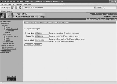
In Figure 8-5, an IP address pool that starts with 10.20.10.1 and ends with 10.20.10.100 is configured. An associated subnet mask of 255.255.255.0 is configured with the address pool. Notice that the IP address pool is configured under Configuration > System > Address Management > Pools.
It is also possible to assign IP addresses to remote access clients using an authentication server (such as a Remote Authentication Dial-In User Service [RADIUS] server) or by using a Dynamic Host Configuration Protocol (DHCP) server. Furthermore, it is possible to allow remote access clients to specify their own IP addresses. These methods of IP address assignment can be configured under Configuration > System > Address Management > Assignment.
Now you might be asking yourself what the IP address assigned by the VPN concentrator to the remote access client is used for. The answer is that it is applied to a VPN tunnel interface. This means that the remote access client will have one or more IP addresses assigned to physical interfaces, as well as the IP address assigned by the VPN concentrator that is applied to the remote access client's VPN tunnel interface (a PPP adapter on Windows systems).
Figure 8-8 shows the output of the ipconfig/all command on a Windows XP remote access client workstation after an L2TP/IPsec VPN tunnel has been established with a Cisco VPN concentrator. This output illustrates the assignment of an IP address to a VPN tunnel interface.
Figure 8-8. Output of the ipconfig /all Command on a Windows XP Remote Access Client Workstation
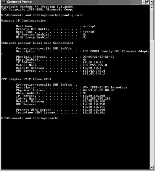
If you look down the output of the ipconfig /all command in Figure 8-8, you can see that the IP address 10.10.10.61 is applied to the Ethernet adapter (interface) and that the IP address 10.20.10.100 has been assigned to the PPP adapter (VPN tunnel interface) of the Windows XP remote access client workstation.
You might like to compare the IP address assigned to the VPN tunnel interface (10.20.10.100) with the IP address pool configured in Figure 8-7. The IP address is one of those in the pool, which is no accident, of coursethe IP address is assigned to the remote access client during PPP (IPCP) negotiation with the Cisco VPN 3000 concentrator.
Step 2: Configure the Base Group
Settings that you specify in the base group can be inherited by other groups and users. You can configure settings such as tunneling protocols, DNS and WINS server addresses, IPsec SA, tunnel type, authentication server, and L2TP (PPP) authentication protocols under the base group.
Figure 8-9 depicts the configuration of DNS and WINS server addresses, as well as tunneling protocols under Configuration > User Management > Base Group > General.
Figure 8-9. Configuration of DNS and WINS Servers as Well as Tunneling Protocols Under the Base Group
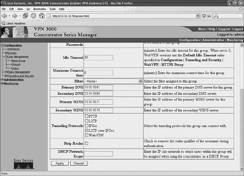
Primary/secondary DNS and WINS server addresses are set to 10.10.10.61/10.10.10.62 and 10.10.10.71/10.10.10.72, respectively, in Figure 8-9. If you look a little farther down the screen, you can see that L2TP over IPsec has been selected as a tunneling protocol.
In Figure 8-10, the IPsec SA, tunnel type, authentication server, and default PSK are configured under Configuration > User Management > Base Group > IPSec.
Figure 8-10. Configuration of IPsec SA, Tunnel Type, and Authentication Server Under the Base Group

Starting at the top of the screen shown in Figure 8-10, the IPsec SA is selected as ESP-L2TP-TRANSPORT, the tunnel type is configured as Remote Access, and in this example, the authentication server is configured as Internal. The authentication server is used to authenticate the users of L2TP/IPsec remote access VPN client workstations during PPP authentication. Note that you might also have to enable L2TP (by checking the appropriate box) under Configuration > Tunneling and Security.
Figure 8-11 shows the configuration of a default PSK under Configuration > User Management > Base Group > IPSec.
Figure 8-11. Configuration of a Default PSK Under the Base Group
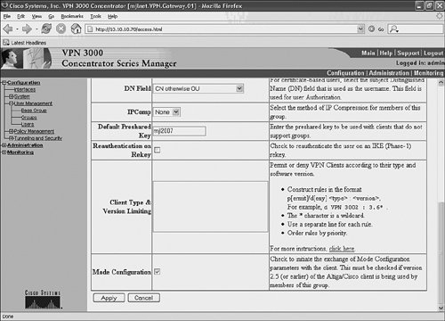
In Figure 8-11, the default PSK, mjl2007, is configured on the Cisco VPN concentrator.
Note
The PSK shown in Figure 8-11 is not secure. In a real deployment, a PSK should be a random (as possible) alphanumeric string.
Next, L2TP (PPP) authentication is configured under Configuration > User Management > Base Group > PPTP/L2TP (see Figure 8-12).
Figure 8-12. L2TP (PPP) Authentication Is Configured Under the Base Group
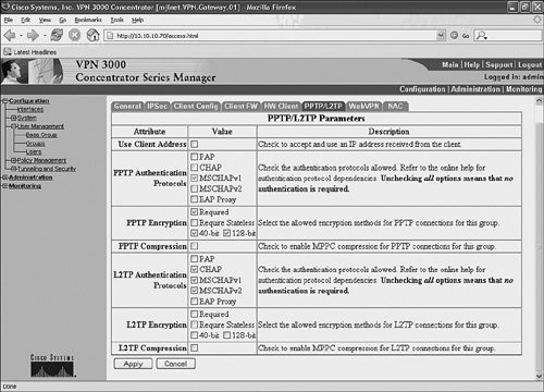
In this example (Figure 8-12), CHAP, MS-CHAPv1, and MS-CHAPv2 are configured as L2TP (PPP) authentication protocols. Note also that none of the L2TP encryption options are checked. Because this configuration is for L2TP/IPsec, you might be mystified as to why no encryption is configured here. In fact, the encryption options here correspond to Microsoft Point-to-Point Encryption (MPPE), which can be used to encrypt the PPP frames carried over the L2TP tunnel. In this case, however, IPsec protects the L2TP tunnel, so MPPE is not necessary.
Also, notice that L2TP compression is not selected in this example. If you select L2TP compression, Microsoft Point-to-Point Compression (MPPC) is used to compress PPP frames over the L2TP tunnel. Compression can be used to make efficient use of bandwidth but does incur additional memory and CPU overhead on the Cisco VPN concentrator. For this reason, it is usually only a good idea to configure compression if all remote access VPN client users use dialup connections.
Step 3: Configure L2TP/IPsec Remote Access Client User Accounts
Having configured the base group, the next step is to configure L2TP/IPsec remote access user accounts. Within user accounts, you can configure usernames and passwords. Figure 8-13 illustrates the configuration of a user account under Configuration > User Management > Users.
Figure 8-13. Configuration of a User Account
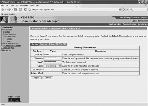
As shown in Figure 8-13, a user account with username mark is configured. A password is also configured. The username and password are used during PPP authentication. Notice that user mark is in the base group. Although not shown, other settings under the user's General, IPsec, PPTP/L2TP tabs of the user account include settings inherited from those settings configured under the base group (see Figures 8-9 through 8-12).
Step 4: Modify IPsec Parameters such as IKE and IPsec SA Proposals (Optional)
It is also possible to modify the IKE and IPsec SA proposals used with L2TP/IPsec by going to Configuration > Policy Management > SAs, selecting ESP-L2TP-TRANSPORT, and clicking Modify (see Figure 8-45 on page 758).
You can modify IKE phase 1 (main mode) proposals under the IKE Parameters heading (in particular, IKE Proposal) in the lower part of the screen and IKE phase 2 (quick mode) proposals under the IPSec Parameters heading (in particular, Authentication Algorithm and Encryption Algorithm) in the upper part of the screen.
The defaults should work fine with Windows clients, but you might want to choose stronger algorithms. The important point is that at least one of the main mode proposals that the remote access client sends during IKE phase 1 negotiation must match the IKE proposal that is specified on the VPN 3000 concentrator, and one of the quick mode proposals that the remote access client sends during IKE phase 2 negotiation must match the IPSec parameters that are specified on the VPN 3000 concentrator.
One way to find out what IKE proposals a Windows client is sending is to examine the oakley.log and look for MMOffer entries (main mode proposals) and QMOffer entries (quick mode proposals). If you are not sure, however, it is best to leave the parameters and proposals at their defaults. For more information on the oakley.log, see the section "Verifying L2TP/IPsec VPNs on Remote Access Client Workstations" later in this chapter.
Configuring a Cisco IOS Router as an L2TP/IPsec VPN Gateway for PSK Authentication
To configure a Cisco IOS router as an L2TP/IPsec VPN gateway, you must complete the following steps:
|
Step 1. |
Configure a local username/password database or authentication, authorization, and accounting (AAA). |
|
Step 2. |
Globally enable Virtual Private Dialup Networks (VPDN). |
|
Step 3. |
Configure VPDN groups. |
|
Step 4. |
Configure virtual templates. |
|
Step 5. |
Configure IP address pools and other IP options. |
|
Step 6. |
Configure IPsec protection for L2TP. |
Example 8-4 shows the configuration of a Cisco IOS router as an L2TP/IPsec remote access VPN gateway.
Example 8-4. Configuration of a Cisco IOS Router as an L2TP/IPsec Remote Access VPN Gateway
! hostname mjlnet.VPN.Gateway.03 (line 1) ! ! username mark@mjlnet.com password 0 mjlnet2006 (line 2) username john@mjlnet.com password 0 mjlnet2007 (line 3) ! vpdn enable (line 4) ! vpdn-group 1 (line 5) accept-dialin (line 6) protocol l2tp (line 7) virtual-template 1 (line 8) l2tp security crypto-profile l2tpprof (line 9) no l2tp tunnel authentication (line 10) ! ! async-bootp dns-server 10.10.10.61 (line 11) async-bootp nbns-server 10.10.10.71 (line 12) ! crypto isakmp policy 1 (line 13) authentication pre-share (line 14) crypto isakmp key mjl2007 address 0.0.0.0 0.0.0.0 (line 15) ! crypto ipsec transform-set l2tptrans esp-3des esp-md5-hmac (line 16) mode transport (line 17) ! crypto map l2tpmap 10 ipsec-isakmp profile l2tpprof (line 18) set transform-set l2tptrans (line 19) ! ! interface Loopback0 (line 20) ip address 10.30.10.1 255.255.255.0 (line 21) ! interface FastEthernet0/0 (line 22) ip address 10.10.10.1 255.255.255.0 (line 23) ! interface FastEthernet2/0 (line 24) ip address 10.40.10.1 255.255.255.0 (line 25) crypto map l2tpmap (line 26) ! interface Virtual-Template1 (line 27) ip unnumbered Loopback0 (line 28) peer default ip address pool RA_VPN_pool (line 29) ppp authentication chap (line 30) ! ! ip local pool RA_VPN_pool 10.20.10.1 10.20.10.100 (line 31) ! |
Lines 2 and 3 show the configuration of a local username/password database using the username username password password command. These usernames and passwords are used for user authentication that takes place during PPP negotiation.
The vpdn enable command in line 4 is then used to globally enable VPDNs, including L2TP. After VPDNs have been globally enabled, the next step is to configure the VPDN group. A VPDN group is used to group L2TP configuration on the VPN gateway. The vpdn-group name command in line 5 is used to configure the (locally significant) name of a VPDN group.
In line 6, the accept-dialin command configures the VPN gateway to accept L2TP tunnel and session setup from remote access VPN clients.
The protocol l2tp command in line 7 is then used to configure the VPDN protocol as L2TP.
In line 8, the virtual-template template-number command is used to specify the virtual template from which virtual access interfaces will be copied (see lines 27 to 30). PPP connections (tunneled by L2TP) from remote access VPN clients are terminated on virtual access interfaces.
The l2tp security crypto-profile profile-name command (line 9) is used to enable IPsec protection for L2TP (L2TP/IPsec). The profile name specified using this command must match that configured using the crypto map map-name sequence-number ipsec-isakmp profile profile-name command in line 16.
In line 10, the no l2tp tunnel authentication command is used to ensure that authentication is not used for L2TP tunnel. L2TP tunnel authentication is unnecessary in this case because remote access VPN client machines are authenticated during IKE negotiation and the users are authenticated during PPP negotiation.
Lines 11 and 12 contain the async-bootp dns-server address and async-bootp nbns-server address commands. These commands configure DNS server and NetBIOS Name Server (WINS server) addresses, and these are supplied to remote access VPN clients in PPP (IPCP) negotiation.
Lines 13 to 14 show the configuration of the IKE policy. In this case, the policy consists of DES encryption, Diffie-Hellman group 1, a lifetime of 86,400 seconds, and PSK authentication (authentication pre-share). Because the encryption algorithm, Diffie-Hellman group, and lifetime are defaults, their configuration is not explicitly shown.
The crypto isakmp key preshared-key address peer-address mask command in line 15 is used to specify the PSK used to authenticate remote access VPN client machines with any IP address. Remote access VPN client machines can have any IP address because a wildcard address and mask are specified (0.0.0.0/0.0.0.0).
An IPsec transform set is configured in lines 16 and 17.
The crypto ipsec transform-set transform-set-name transform1 [transform2] [transform3] [transform4] command in line 16 is used to configure a transform set called l2tptrans that specifies ESP-3DES encryption and ESP-MD5-HMAC authentication. If you have Windows remote access VPN clients, do not specify AH in the transform set; it is not supported with the Windows L2TP/IPsec client.
The mode {tunnel | transport} command in line 17 is used (in this case) to specify transport mode. If you have Windows remote access VPN clients, make sure that you specify transport mode as tunnel mode is not supported by the Windows L2TP/IPsec client.
In lines 18 and 19, a crypto map is created using the crypto map map-name sequence-number ipsec-isakmp profile profile-name command, and the transform-set created in lines 16 and 17 is specified using the set transform-set transform-set-name command.
The profile keyword in the crypto map map-name sequence-number ipsec-isakmp profile profile-name command is used to allow crypto maps to be created on demand from this template as remote access VPN clients connect to the VPN gateway.
Lines 20 to 26 show the configuration of loopback, inside, and outside interfaces. Note that crypto map created in lines 18 and 19 is applied to the outside interface (the interface on which remote access VPN clients will connect).
In lines 27 to 30, a virtual template interface is configured. This virtual template is referenced with the virtual-template command in line 8.
In line 28, the ip unnumbered interface command configures the virtual template to use the IP address configured on interface Loopback0.
The peer default ip address pool pool-name command (line 29) references a pool of IP addresses. IP addresses from this pool are supplied to remote access VPN clients during PPP (IPCP) negotiation.
In line 30, the ppp authentication chap configures the VPN gateway to authenticate remote access VPN clients using CHAP.
The ip local pool pool-name command in line 31 specifies an IP address pool. As previously mentioned, IP addresses from this pool are supplied to remote access clients (see also line 29).
The sample configuration shown in Example 8-4 includes the configuration of a local username/password database (lines 2 and 3) that is used for remote access user authentication. Although a local database works well for a small number of users, it does not scale well. It is common, therefore, to use an AAA server (often a RADIUS server) for user authentication.
To use RADIUS rather than a local username/password database, the commands in lines 2 and 3 (Example 8-4) can be replaced by the configuration contained in Example 8-5.
Example 8-5 shows the AAA configuration for a Cisco IOS VPN gateway.
Example 8-5. Configuration for User Authentication Using a RADIUS Server
aaa new-model aaa authentication ppp default group radius aaa authorization network default group radius radius-server host 10.10.10.51 auth-port 1645 acct-port 1646 key cisco |
The aaa new-model command enables AAA.
Next, the aaa authentication ppp default group radius command enables authentication for PPP using a RADIUS server using the default method list.
The aaa authorization network default group radius command configures authorization of network connections using a RADIUS server (using the default method list).
The radius server host command specifies the IP address/DNS name of the RADIUS server as well as the UDP ports used for authentication (auth-port) and accounting (acct-port) requests. This command is also can also be used to specify the key used to authenticate communications used between the VPN gateway and the RADIUS server.
It is also worth mentioning that you should make sure that user accounts on the RADIUS server specify the Service-Type (attribute type 6) as Framed, and the Framed-Protocol (attribute type 7) as PPP (configured, by default, under the group on a Cisco Secure ACS).
You can verify L2TP/IPsec remote access VPNs on a Cisco IOS router using a number of commands, including show vpdn tunnel, show vpdn session, and show caller user. These commands are discussed in detail later in this chapter.
Configuring Windows L2TP/IPsec Remote Access VPN Clients for PSK Authentication
After you have configured the VPN gateway, you can move on to configuring the L2TP/IPsec remote access VPN clients.
The configuration of a Windows XP L2TP/IPsec remote access client for PSK authentication begins with the following steps:
|
Step 1. |
Go to the Control Panel (via the Start menu). |
|
Step 2. |
Click Network and Internet Connections. |
|
Step 3. |
Click Network Connections. |
|
Step 4. |
Click Create a new connection. |
You will then be presented with the Welcome to the New Connection Wizard screen (see Figure 8-14).
Figure 8-14. Welcome to the New Connection Wizard Screen
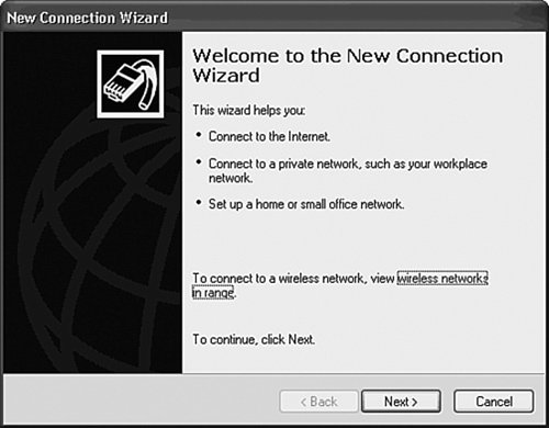
Click Next, and you will see the New Connection Type screen shown in Figure 8-15.
Figure 8-15. New Connection Type Screen

Choose Connect to the network at my workplace and click Next. You will now be presented with the Network Connection screen (see Figure 8-16).
Figure 8-16. Network Connection Screen

Choose Virtual Private Network connection and click Next. Now you will see the Connection Name screen in Figure 8-17.
Figure 8-17. Connection Name Screen
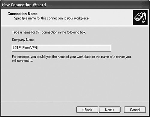
Type in a name for the VPN connection. It does not particularly matter what name you choosejust make it something meaningful. After you have typed a name for the connection, click Next, and you may see the Public Network screen in Figure 8-18.
Figure 8-18. Public Network Screen
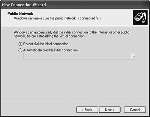
At this point, you must choose whether you want a (previously configured) dialup connection to be triggered when you initiate VPN connectivity. If you have a DSL or cable Internet connection, you should choose Do not dial the initial connection; if you have a dialup connection, however, choose Automatically dial this initial connection and then choose a dialup connection from the drop-down box.
Click Next, and the VPN Server Selection screen in Figure 8-19 will appear.
Figure 8-19. VPN Server Selection Screen
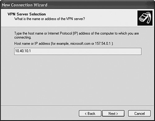
You can either type the IP address or the fully qualified domain name (FQDN) of the VPN gateway in the box. After you have done this, click Next.
Figure 8-20 shows the final screen, Completing the New Connection Wizard.
Figure 8-20. Completing the New Connection Wizard Screen
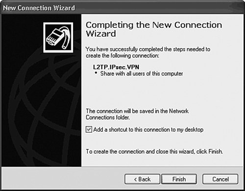
Click Next. You have now finished creating your VPN connection.
As you've been following the configuration of the Windows XP remote access VPN client, you might have noticed that one thing was missingat no point did you specify the VPN protocols (L2TP over IPsec). And neither did you specify PSK or PPP authentication.
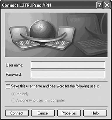
You will not be surprised to learn that the VPN connection that you have just created requires a little tweaking. Open the VPN connection you just created either by double-clicking the shortcut (if you created one) or by going to the Control Panel and clicking Network And Internet Connections and then clicking Network Connections. You will now see the dialog box in Figure 8-21.
Figure 8-21. Connection Dialog Box
Click Properties, and then the Security tab, choose Advanced (custom settings), and click the Settings button. You will see the screen in Figure 8-22.
Figure 8-22. Advanced Security Settings Screen

Click the Data encryption drop-down and choose Require encryption (disconnect if server declines). It is important that you do not choose No encryption allowed (server will disconnect if it requires encryption)if you specify this option, the remote access VPN client will attempt to negotiate null (RFC2410) IPsec encryption (meaning no encryption) during IKE phase 2! Do not worry too much, however, because any attempt by the remote access client to negotiate null encryption will fail, unless, that is, you specify the null encryption algorithm on the VPN gateway (almost always a bad idea!).
In the lower part of the dialog box, you can choose the appropriate PPP authentication protocols, one of which must match those configured on the VPN gateway (see Figure 8-12 and line 30 in Example 8-4).
Click OK, and you're now back to the Security tab. Now click the IPSec Settings button, and the IPSec dialog box will appear (see Figure 8-23).
Figure 8-23. IPSec Settings Dialog Box
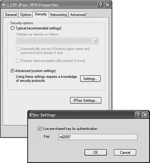
Check the Use pre-shared key for authentication and type same preshared key that you configured on the VPN gateway (see Figure 8-11 and line 14 in Example 8-4) into the box.
Click OK, followed by the Networking tab, and you will see the screen shown in Figure 8-24.
Figure 8-24. The Networking Tab
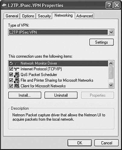
In the Type of VPN drop-down box, choose L2TP IPSec VPN.
Finally, click OK, and the configuration of your L2TP/IPsec remote access VPN client is complete.
Although not shown, you might also like to choose Internet Protocol (TCP/IP) (see Figure 8-24), click the Properties button, and in the General tab of the Advanced TCP/IP Settings ensure that the Use default gateway on remote network is checked. This ensures that the Windows XP client will use the VPN gateway as its default gateway when the VPN is connected, thus preventing split tunneling.
Caution
Split tunneling is a situation in which a remote access client can directly access both the Internet and the VPN tunnel at the same time. This situation is a security risk because an attacker on the Internet might be able to gain control of the remote access client and then access the VPN tunnel.
Configuration of Windows 2000 workstations for L2TP/IPsec is similar to that to that for Windows XP, in that you must create the VPN connection via the Make New Connection Wizard accessible from Network and Dial-up Connections in the Control Panel. However, there is no easy way to specify a PSK in Windows 2000you have to do the following:
- Add a value called ProhibitIpSec to the registry. This disables the automatic creation of an IPsec policy for L2TP (the automatically created policy uses digital signature [digital certificate] IPsec authentication).
- Manually create an IPsec policy for L2TP with PSK authentication.
You can find detailed information on these tasks in Microsoft Knowledge Base article 240262. Just search for this article at http://www.microsoft.com.
Note
It is also possible to obtain L2TP/IPsec client software for Windows 98, Windows ME, and Windows NT 4.0 from the following URL:
http://www.microsoft.com/technet/prodtechnol/windows2000serv/support/vpnclientag.mspx
Other operating systems such as MacOS X include L2TP/IPsec remote access client software.
Implementing Digital Signature (Digital Certificate) Authentication with L2TP/IPsec Voluntary/Client-Initiated Tunnel Mode Remote Access VPNs
As already described, PSK is a relatively easy to configure method IPsec (IKE) authentication, but a more secure method of IPsec authentication using digital signatures (digital certificates). If you want to implement digital signature authentication, you must configure this on both the VPN gateway and the remote access VPN clients.
Configuring the L2TP/IPsec VPN Gateway for Digital Signature Authentication
This section examines the configuration of a Cisco VPN 3000 concentrator and a Cisco IOS router as an L2TP/IPsec VPN gateway for digital signature authentication.
Specifying Digital Signature Authentication on a Cisco VPN 3000 Concentrator
The configuration of a Cisco VPN 3000 concentrator consists of the following:
|
Step 1. |
Retrieve and install the CA's certificate. |
|
Step 2. |
Enroll the VPN gateway with the CA and obtain a certificate. |
|
Step 3. |
Configure an address pool (or other method of IP address assignment). |
|
Step 4. |
Configure the base group. |
|
Step 5. |
Configure a group for L2TP/IPsec remote access client users. |
|
Step 6. |
Configure L2TP/IPsec remote access client user accounts. |
|
Step 7. |
Modify IPsec parameters such as IKE and IPsec SA proposals (optional). |
Notice that the configuration steps are almost identical to those necessary when configuring PSK authentication. The differences are described in Steps 1, 2, and 5. This section does not repeat Steps 3, 4, and 6see the section "Configuring the L2TP/IPsec VPN Gateway for PSK Authentication" for more information on these steps. Steps 1, 2, and 5 are discussed further in the following three sections.
Step 1: Retrieve and Install the CA's Certificate
In Step 1, you must retrieve the CA's certificate and install it on the Cisco VPN 3000 concentrator.
Note
A Microsoft certificate server is used to illustrate example configurations in this chapter. This does not constitute a recommendation, and it should be noted that many other vendors produce similar products that can support the same functions.
Two methods of retrieving and installing the CA's certificate are as follows:
- Manually retrieving and installing the CA's certificate
- Using the Simple Certificate Enrollment Protocol (SCEP) to retrieve and install the CA's certificate
This chapter focuses on manual retrieval and installation; Chapter 9, "Designing and Deploying IPsec Remote Access and Teleworker VPNs," discusses retrieval using SCEP.
To retrieve the CA's certificate manually, navigate to the following URL (inserting either the IP address or the FQDN of the certificate server, as appropriate):
http://<CA_ip_address_or_CA_FQDN>/certsrv
Figure 8-25 shows the first page that you will see when retrieving the CA's certificate.
Figure 8-25. Certificate Services Welcome Page
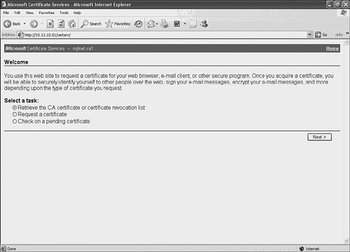
As shown in Figure 8-25, on the Welcome page, choose Retrieve the CA certificate or certificate revocation list, and then click Next.
You will then see the page shown in Figure 8-26.
Figure 8-26. Retrieve the CA Certificate or Certificate Revocation List Page
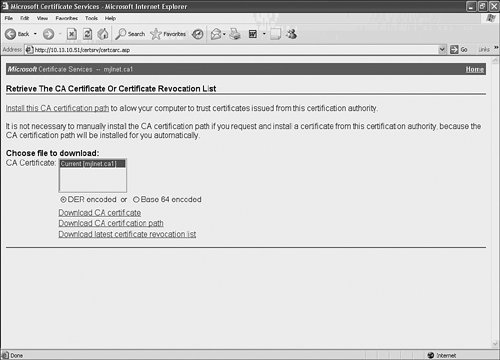
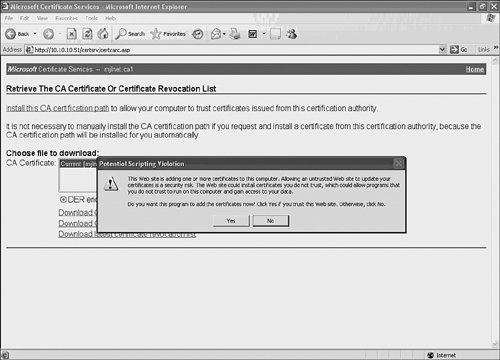
On the Retrieve the CA certificate or certificate revocation list page, click the Download CA certificate link.
A dialog box titled Potential Scripting Violation followed by a dialog box titled Security Warning may appearchoose Yes in both, and save the CA's certificate to a convenient location on the local workstation.
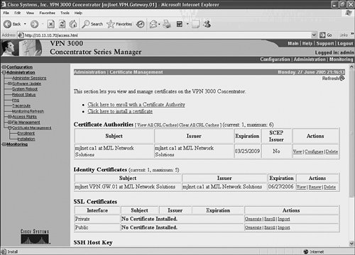
Now go to Administration > Certificate Management on the Cisco VPN 3000 concentrator (see Figure 8-27). Notice that there is no existing certificate listed under the Certificate Authorities heading.
Figure 8-27. Certificate Management Page
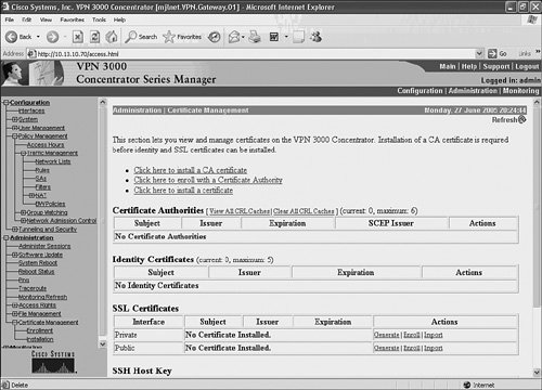
Choose the Click here to install a CA certificate link and on the following page choose Upload File from Workstation and browse to location that you saved the CA's certificate to on the local workstation.
Figure 8-28 shows the Administration > Certificate Management > Install > CA Certificate > Upload File from Workstation page.
Figure 8-28. Upload File from Workstation Page
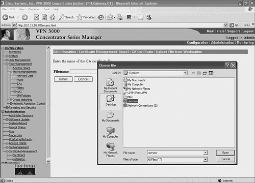
Select the CA's certificate and click the Install button. The CA's certificate is installed, and you will jump back to the Certificate Management page (see Figure 8-29).
Figure 8-29. Certificate Management Page (the CA's Certificate Is Installed)
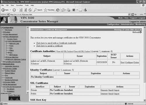
If you take a close look under the Certificate Authorities heading in Figure 8-29, you will notice that the CA's certificate has now been installed on the Cisco VPN 3000 concentrator. So far so good. Now you've got to enroll the VPN gateway with the CA.
Step 2: Enroll the VPN Gateway with the CA and Obtain a Certificate
Having obtained the CA's certificate and installed it on the VPN gateway, you are ready to enroll the VPN gateway itself and obtain an identity certificate for it.
The first task in this step is to go to the Configuration > Certificate Management page on the Cisco VPN 3000 concentrator (see Figure 8-29). Choose Click here to enroll with a Certificate Authority, and you will find yourself on the page shown in Figure 8-30.
Figure 8-30. Choosing an Enrollment Method
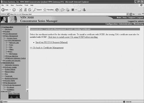
Choose Enroll via PKCS10 Request (Manual), and the page in Figure 8-31 will appear.
Figure 8-31. Entering Information to Be Included in the Certificate Request
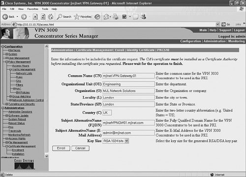
Fill in the fields appropriatelythis information will be included in the X.509 certificate that is issued by the CA. After you have completed filling in the information, click the Enroll button; you will see a page similar to that shown in Figure 8-32.
Figure 8-32. PKCS#10 Certificate Request
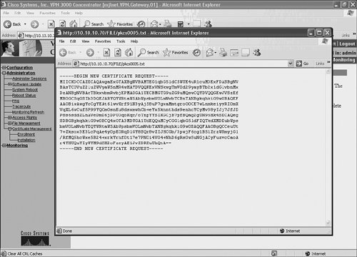
If you do not see a screen similar to that shown in Figure 8-32, it might be because you have pop-ups blocked in your web browserdon't worry, the PKCS request is stored as a file that you can also view by going to Configuration > File Management (it is stored as a PKCSxxxx.TXT file).
Copy the text shown in the browser window (Figure 8-32) and then open a separate browser window to the following URL:
http://<CA_ip_address_or_CA_FQDN>/certsrv
Choose Request a certificate and click Next. You will then see the page shown in Figure 8-33.
Figure 8-33. Choose Request Type

Now choose Advanced request and click Next, and you should see the screen in Figure 8-34.
Figure 8-34. Advanced Certificate Requests
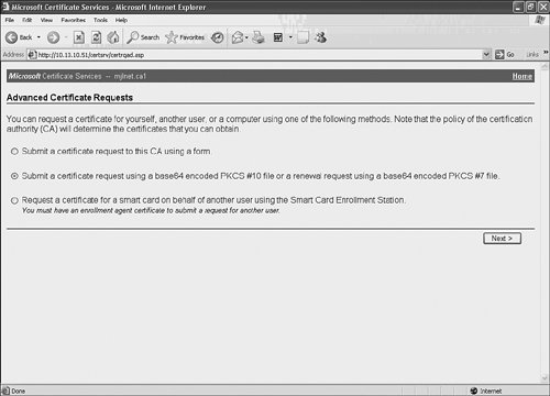
As shown in Figure 8-34, choose Submit a certificate request using a base64 encoded PKCS#10 file or renewal request using base64 encoded PKCS#7 file and then click Next.
Figure 8-35 shows the page that now appears.
Figure 8-35. Submit a Saved Request
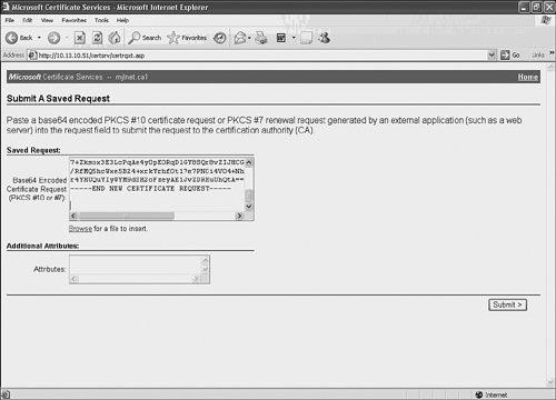
When you arrive at the Submit a Saved Request page (Figure 8-35), paste the PKCS request from Figure 8-32 into the Saved Request box and then click the Submit button.
Next, you are presented with the page shown in Figure 8-36.
Figure 8-36. Certificate Pending
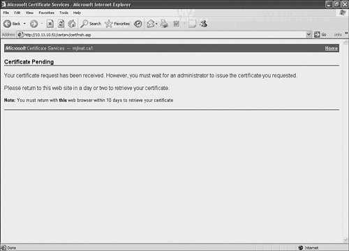
Your certificate request is now pending on the CA, and must be approved by the CA administrator before a certificate can be issued (assuming that the CA is not configured to automatically issues certificates [almost always a bad idea!]).
Figure 8-37 shows the approval and certificate issuance process on a Microsoft CA.
Figure 8-37. Approval and Certificate Issuance on a Microsoft CA

As shown in Figure 8-37, you can check whether the requested certificate has been issued by the going back to the following URL:
http://CA_ip_address_or_CA_FQDN/certsrv
Figure 8-38 shows the procedure for checking whether a certificate has been issued.
Choose Check on pending certificate, click Next, select the certificate request, click Next again, and you will be presented with the screen shown in Figure 8-39, assuming that the certificate has been issued by the CA administrator. If the certificate has not yet been issued, you will see a message to this effect.
Figure 8-38. Checking Whether a Certificate Has Been Issued

Figure 8-39. Certificate Has Been Issued
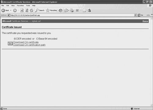
You should now click Download CA certificate and save the certificate to a convenient location on the local workstation.
The next step is to upload the certificate to the Cisco VPN 3000 concentrator. You can do this by navigating to Administration > Certificate Management > Install (see Figure 8-40).
Figure 8-40. Installing the Certificate on the Cisco VPN 3000 Concentrator
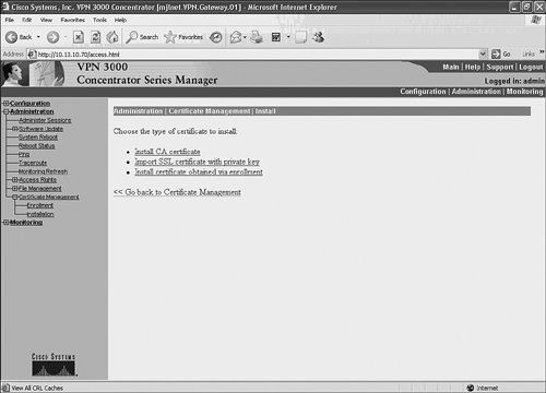
You should now click Install certificate obtained via enrollment, and you will come to the Enrollment Status page.
Click Install under the Actions heading, followed by Upload File from Workstation, and then upload the certificate you just saved to the local workstation to the Cisco VPN 3000 concentrator (see Figure 8-41) by browsing to the location of the file (certificate) and clicking Install.
Figure 8-41. Installing the Identity Certificate on the Cisco VPN 3000 Concentrator
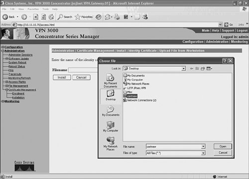
After you have installed the identity certificate, it will appear under the Identity Certificates heading under Administration > Certificate Management (see Figure 8-42).
Figure 8-42. Identity Certificate Has Been Installed
You have now obtained and installed both CA and identity certificates on the Cisco VPN 3000 concentrator, and you are ready to configure a group for L2TP/IPsec remote access client users.
Step 5: Configure a Group for L2TP/IPsec Remote Access Client Users
There is one important fact to remember when configuring a group with digital signature authenticationby default, the name of the group to which remote access clients belong must match the department name that you specify during enrolment for L2TP/IPsec remote access clients.
Figure 8-43 shows the configuration of a group whose name (Engineering in this case) matches that of the department to which L2TP/IPsec remote access clients belong.
Figure 8-43. Configuration of a Group for L2TP/IPsec Remote Access Clients
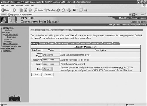
By going to Configuration > User Management > Groups and selecting Add Group, you will be presented with the screen shown in Figure 8-43. Then simply type in the group name (which as previously mentioned must correspond to the Department [OU] of remote access user clients certificates). Type in any password and then click Add.
After the group has been added, you can begin to create the account for the remote access users as described in the section "Configure L2TP/IPsec Remote Access Client User Accounts" earlier in this chapter but with the important difference that you should assign the users to the group that you have just created.
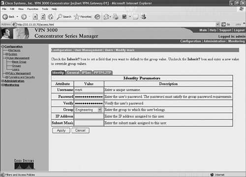
Figure 8-44 illustrates assignment of a remote access VPN user to a group called Engineering.
Figure 8-44. Assignment of a Remote Access User to a Group Called Engineering
Step 7: Modify IPsec Parameters Such as IKE and IPsec SA Proposals
As discussed in the section "Configure the Base Group" earlier in this chapter, under Configuration > User Management > Base Group, IPSec tab, you should choose the IPSec SA called ESP-L2TP-TRANSPORT for use with L2TP/IPsec remote access VPNs.
You can examine and, if necessary, modify the parameters and algorithms associated with ESP-L2TP-TRANSPORT by going to Configuration > Policy Management > Traffic Management > SAs and then choosing ESP-L2TP-TRANSPORT and clicking Modify. Figure 8-45 shows the algorithms and parameters associated with ESP-L2TP-TRANSPORT.
Figure 8-45. Modifying Algorithms and Parameters Associated with ESP-L2TP-TRANSPORT
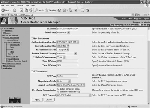
If you take a look at the IPSec Parameters section of the screen shown in Figure 8-45, you can see the algorithms and parameters contained in the Cisco VPN 3000 concentrator SA proposals used for IKEv1 phase 2 (quick mode) negotiation.
The lower section of the screen (IKE Parameters) contains the algorithms and parameters contained in the Cisco VPN concentrators SA proposals used for IKEv1 phase 1 negotiations.
The only parameter that it is usually necessary to modify when configuring digital signature authentication for L2TP/IPsec remote access VPNs is shown under the IKE Parameters section of the page in Figure 8-45. Specifically, you should choose the identity certificate that you have just obtained for the Cisco VPN 3000 concentrator in the Digital Certificate drop-down box (see the section "Step 2: Enroll the VPN Gateway with the CA and Obtain a Certificate").
After you have selected the identity certificate, click Apply, and you are done (as far as the VPN concentrator is concerned)the Cisco VPN 3000 concentrator is now ready to terminate L2TP/IPsec remote access VPN tunnels from remote access users.
Implementing Digital Signature Authentication on a Cisco IOS VPN Gateway
The configuration of a Cisco IOS VPN gateway for digital signature is similar to that for PSK authentication. The difference is that you must, of course, configure IKE digital signature authentication and specify the authentication rsa-sig command rather than the authentication pre-share command (line 14 in Example 8-4), as well as remove the crypto isakmp key preshared-key address peer-address mask command in line 15 of Example 8-4.
See the section "IKE Digital Signature Authentication" in Chapter 6 on page 448 for detailed information about configuring digital signature authentication on a Cisco IOS router.
Configuring Windows L2TP/IPsec Remote Access Clients for Digital Signature (Digital Certificate) Authentication
The configuration of Windows XP/2000 L2TP/IPsec remote access clients for digital signature authentication is similar to that when using PSK authenticationthe difference is, of course, that you must obtain the CA's certificate and then an identity certificate for the remote access client workstation.
The configuration of Windows XP/2000 L2TP/IPsec remote access clients consists of the following steps:
|
Step 1. |
Obtain and install the CA's certificate on the L2TP/IPsec remote access VPN client. |
|
Step 2. |
Enroll and obtain an identity certificate for the remote access VPN client workstation. |
|
Step 3. |
Create an L2TP/IPsec VPN connection using the Create a New Connection Wizard (accessible via the Control Panel). |
Steps 1 and 2 are described in the following sections. Step 3 is actually the same as previously described in the section "Configuring Windows L2TP/IPsec Remote Access VPN Clients for PSK Authentication," but with the exception that you should not configure a PSK (the default method of authentication for L2TP/IPsec on Windows clients is digital signature authentication).
Step 1: Obtain and Install the CA's Certificate on the L2TP/IPsec Remote Access VPN Client
The process of obtaining the CA's certificate for a L2TP/IPsec remote access client workstation is similar to that described in the section "Step 1: Retrieve and Install the CA's Certificate" on page 743the difference is that instead of clicking Download CA Certificate and temporarily saving the CA's certificate to a convenient location on the local workstation, and subsequently uploading the CA's certificate to the Cisco VPN 3000 concentrator, you must click the Install this CA certificate path in the upper-left corner of the Retrieve the CA Certificate or Certificate Revocation List page. When you click the Install this CA certification path link, the message shown in Figure 8-46 appears. Click Yes, and the CA's certificate will be installed.
Figure 8-46. Obtain and Install the CA's Certificate
Step 2: Enroll and Obtain an Identity Certificate for the Remote Access VPN Client Workstation
After you have obtained and installed the CA's certificate, you can install the identity certificate on the L2TP/IPsec remote access VPN client workstation.
On the remote access VPN client workstation, navigate to the following URL:
http://CA_ip_address_or_CA_FQDN/certsrv
Choose Request a certificate and click Next. You will now see the page shown in Figure 8-47. Choose Advanced request and click Next. The page shown in Figure 8-48 will now appear.
Figure 8-47. Choose Request Type Page
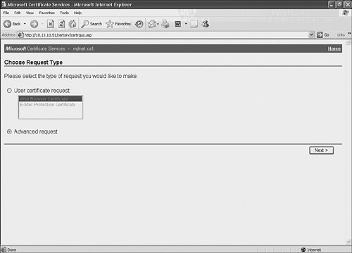
Figure 8-48. Advanced Certificate Requests

Choose Submit a certificate request to this CA using a form and then click Next. The form shown in Figure 8-49 will now appear.
Figure 8-49. Advanced Certificate Request Form

Fill in the form as appropriate. Choose IPSec Certificate as the Intended Purpose as well as Use local machine store under Key Options (not shown).
One thing to remember here is that the department under the Identifying Information section is later included as the OU within the Subject field of the identity certificate that the CA issues to the remote access VPN client workstation. If you have a good memory, you will remember that the department (Subject/OU) should match the group configured for L2TP/IPsec remote access VPN clients on the Cisco VPN 3000 concentrator (see the section "Step 5: Configure a Group for L2TP/IPsec Remote Access Client Users" on page 756).
Click Submit, and you might see a message stating that your certificate request is pending. The CA administrator must issue the certificate, and after he/she has, you can navigate back to the URL mentioned earlier in this section. Choose Check on pending certificate and click Next.
You will then be presented with a page on which you can select the certificate request in question. Choose the appropriate certificate request, click Next, and you will see a page indicating that the certificate has been issued, as shown in Figure 8-50.
Figure 8-50. Certificate Issued
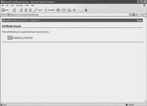
Now click Install this certificate. You should see a message indicating that the certificate has been successfully installed. You can verify the installation of both the CA and identity certificates on the L2TP/IPsec remote access VPN client workstation as follows:
|
Step 1. |
From the Start menu, choose Run, type mmc, and click OK. |
|
Step 2. |
From the File menu, choose Add/Remove Snap-in. |
|
Step 3. |
Click Add, choose Certificates, and click Add. |
|
Step 4. |
Choose Computer account and click Next. |
|
Step 5. |
Choose Local computer: (the computer this console is running on) and click Finish. |
|
Step 6. |
Click Close, and then click OK. |
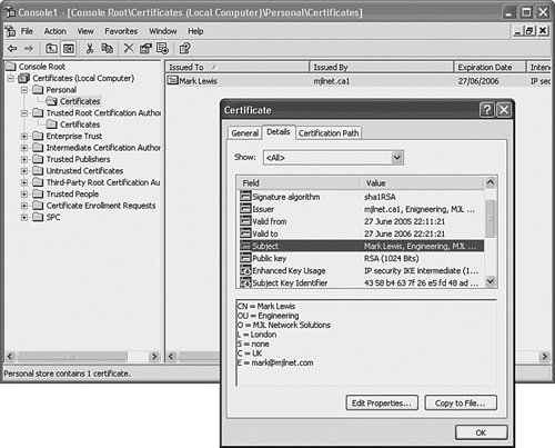
If you look under Console Root > Certificates (Local Computer) > Personal > Certificates (on the left side of the MMC), you should be able to see the identity certificate that you have just obtained from the CA. Figure 8-51 illustrates the verification of the identity certificate.
Figure 8-51. Verification of the Identity Certificate Using the MMC
Under Console Root > Certificates (Local Computer) > Trusted Root Certification Authorities > Certificates, you should be able to see the CA's certificate (see Figure 8-52).
Figure 8-52. Verification of the CA Certificate Using the MMC
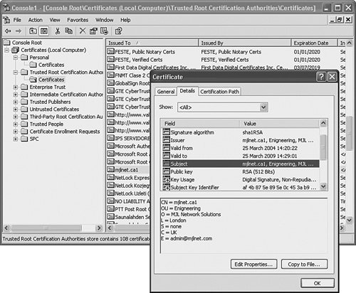
As shown in Figure 8-52, a certificate for CA mjlnet.ca1 is included in the Trusted Root Certification Authorities/Certificates folder. Note that if you cannot see the certificate here, you may find it in the Intermediate Certification Authorities/Certificates folderif so, you can copy it to the Trusted Root Certification Authorities/Certificates folder.
Verifying L2TP/IPsec Voluntary Tunnel Mode Remote Access VPNs
You can verify L2TP/IPsec remote access VPN in a variety of ways, depending on the particular VPN gateway you are using and on the type of remote access client workstations you are using.
Verifying L2TP/IPsec VPNs on the VPN Gateway
If you are using a Cisco VPN 3000 concentrator, you can verify L2TP/IPsec tunnel setup using by going to Monitoring > Filterable Event Log and Monitoring > Filterable Event Log > Live Event Log.
Example 8-6 shows sample output shown in Monitoring > Filterable Event Log after L2TP/IPsec tunnel setup. If you want see these events in real time, you can view them by going to Monitoring > Filterable Event Log > Live Event Log.
Example 8-6. Sample Output Shown in Monitoring > Filterable Event Log After L2TP/IPsec Tunnel Setup
2 06/03/2005 19:59:37.290 SEV=4 IKE/119 RPT=1 192.168.1.1 Group [VPNC_Base_Group] PHASE 1 COMPLETED (line 1) 3 06/03/2005 19:59:37.300 SEV=5 IKE/25 RPT=1 192.168.1.1 Group [VPNC_Base_Group] Received remote Proxy Host data in ID Payload: Address 192.168.1.1, Protocol 17, Port 1701 6 06/03/2005 19:59:37.300 SEV=5 IKE/24 RPT=1 192.168.1.1 Group [VPNC_Base_Group] Received local Proxy Host data in ID Payload: Address 10.40.10.1, Protocol 17, Port 0 9 06/03/2005 19:59:37.300 SEV=5 IKE/66 RPT=1 192.168.1.1 Group [VPNC_Base_Group] IKE Remote Peer configured for SA: ESP-L2TP-TRANSPORT (line 2) 10 06/03/2005 19:59:37.310 SEV=4 IPSEC/7 RPT=1 IPSec ESP Tunnel Inb: invalid direction in security association 11 06/03/2005 19:59:37.310 SEV=4 IKE/49 RPT=1 192.168.1.1 Group [VPNC_Base_Group] Security negotiation complete for User () Responder, Inbound SPI = 0x76a1bb8f, Outbound SPI = 0x69c78e2c 14 06/03/2005 19:59:37.330 SEV=4 IKE/120 RPT=1 192.168.1.1 Group [VPNC_Base_Group] PHASE 2 COMPLETED (msgid=9f3bf228) (line 3) 15 06/03/2005 19:59:37.540 SEV=4 L2TP/57 RPT=1 (line 4) Tunnel to peer 192.168.1.1 established (line 5) 16 06/03/2005 19:59:37.550 SEV=4 L2TP/53 RPT=1 192.168.1.1 (line 6) Session started on tunnel 192.168.1.1 (line 7) 17 06/03/2005 19:59:37.880 SEV=5 PPP/8 RPT=2 192.168.1.1 (line 8) User [mark] (line 8) Authenticated successfully with MSCHAP-V2 (line 10) 18 06/03/2005 19:59:39.700 SEV=5 PPP/49 RPT=2 192.168.1.1 User [mark] IPCP assigned IP Address 10.20.10.101 (line 11) 19 06/03/2005 19:59:39.700 SEV=4 AUTH/22 RPT=2 User [mark] Group [Base Group] connected, Session Type: L2TP/IPSec (line 12) |
In highlighted line 1, you can see the IKEv1 phase 1 has been successfully negotiated, and in highlighted line 2 that the remote peer is configured for the SA named ESP-L2TP-TRANSPORT.
Highlighted line 3 shows that IKEv1 phase 2 has been completed. IPsec negotiation finished, and the IPsec tunnel is up.
Highlighted lines 4 and 5 show that an L2TP tunnel has now been established, and in highlighted line 6 and 7, you can see that an L2TP session has been successfully set up.
PPP negotiation then starts, and in highlighted lines 8 to 10, you can see that user mark has been successfully authenticated using MS-CHAPv2.
Highlighted line 11 shows successful completion of IPCP negotiation. You can see that IP address 10.20.10.101 has been assigned to the remote access VPN client. This IP address will be applied to the remote access VPN client's VPN tunnel interface (PPP adapter).
Finally, highlighted line 12 confirms that user mark in group Base Group is connected via an L2TP/IPsec VPN tunnel.
You can also glean a variety of information regarding L2TP/IPsec VPN tunnels such as number of L2TP/IPsec sessions and detailed information on L2TP and IPsec negotiation and data transport by looking under the Monitoring > Sessions and Monitoring > Statistics.
If you are using a Cisco IOS L2TP/IPsec VPN gateway, you can obtain detailed information concerning L2TP/IPsec tunnel negotiation using the debug crypto isakmp, debug vpdn l2x-events, and debug ppp negotiation commands. The output of these commands was described earlier in this chapter, and so will not be reexamined here. As always, be careful when using debug commands in a production environment.
Other useful commands for verifying L2TP/IPsec on IOS VPN gateways include show vpdn tunnel, show vpdn session, show interface virtual access, show caller user, show crypto isakmp sa, and show crypto ipsec sa.
Example 8-7 shows sample output of the show vpdn tunnel command.
Example 8-7. show vpdn tunnel Command Output
mjlnet.VPN.Gateway.03#show vpdn tunnel %No active L2F tunnels L2TP Tunnel Information Total tunnels 1 sessions 1 (line 1) LocID RemID Remote Name State Remote Address Port Sessions L2TP Class/ VPDN Group 12726 3 markxp1 est 192.168.1.1 1701 1 1 (line 2) %No active PPTP tunnels mjlnet.VPN.Gateway.03# |
Highlighted line 1 shows that 1 L2TP tunnel and 1 session have been negotiated. Then, in highlighted line 2, you can see information including the remote access client computer name (markxp1), the tunnel state (established [est]), the remote access client workstation's (Internet interface) IP address (192.168.1.1), and the VPDN group to which the tunnel corresponds (1).
Note that the computer name shown in Example 8-7 corresponds to that found by right-clicking My Computer, choosing Properties, and choosing the Computer Name tab on a Windows XP workstation.
Example 8-8 shows the output of the show vpdn session command.
Example 8-8. show vpdn session Command Output
mjlnet.VPN.Gateway.03#show vpdn session %No active L2F tunnels L2TP Session Information Total tunnels 1 sessions 1 LocID RemID TunID Username, Intf/ State Last Chg Uniq ID Vcid, Circuit 3 1 12726 mark, Vi2.1 est 00:00:44 2 %No active PPTP tunnels mjlnet.VPN.Gateway.03# |
The highlighted line shows information including the remote access client's username (mark) and the virtual access interface on which the PPP connection is terminated (virtual access interface 2.1). The username shown in Example 8-8 corresponds to that entered in the Connection dialog box on Windows XP remote access clients (see Figure 8-21 on page 740).
If you want more detailed information on L2TP tunnels or sessions, just use the show vpdn tunnel all and show vpdn session all commands, respectively.
You can find out more information on parameters on the virtual access interfaces on which remote access clients' PPP connections are terminated using the show interface virtual access number command (see Example 8-9).
Example 8-9. show interface virtual access Command Output
mjlnet.VPN.Gateway.03#show interface virtual access 2.1 Virtual access2.1 is up, line protocol is up (line 1) Hardware is Virtual Access interface Interface is unnumbered. Using address of FastEthernet2/0 (10.40.10.1) MTU 1500 bytes, BW 10000 Kbit, DLY 100000 usec, reliability 255/255, txload 1/255, rxload 1/255 Encapsulation PPP, LCP Open (line 2) Open: IPCP (line 3) PPPoVPDN vaccess, cloned from Virtual-Template1 (line 4) Vaccess status 0x0 Protocol l2tp, tunnel id 12726, session id 3 (line 5) Keepalive set (10 sec) 27 packets input, 2142 bytes 18 packets output, 320 bytes Last clearing of "show interface" counters never mjlnet.VPN.Gateway.03# |
As you can see, the show interface virtual access command supplies a plethora of information regarding the virtual access interface. Highlighted line 1 shows that interface virtual access 2.1 is in an up/up state. Highlighted lines 2 to 5 show that the encapsulation type is PPP, that the LCP state is Open (LCP has been successfully negotiated), that IPCP is in an Open state (IPCP has been successfully negotiated), that the PPP connection is carried over a VPDN protocol, and finally that the specific VPDN protocol in this case is L2TP.
If your hunger for information is still not sated, you can also use the show caller user command to view remote access client user-specific information (see Example 8-10).
Example 8-10. show caller user Command Output
mjlnet.VPN.Gateway.03#show caller user mark User: mark, line Vi2.1, service PPPoVPDN Connected for 00:02:17, Idle for 00:02:05 Timeouts: Limit Remaining Timer Type - - - PPP: LCP Open, CHAP (<-), IPCP IP: Local 10.40.10.1, remote 10.20.10.1 Counts: 34 packets input, 2254 bytes 25 packets output, 432 bytes mjlnet.VPN.Gateway.03# |
The highlighted lines show that LCP and IPCP are both in an Open state and that CHAP was used to authenticate the remote access client user (rather than the workstation, which is authenticated during IKEv1 phase 1 using either PSKs or digital signatures).
You can see that IP address associated with the virtual access interface on the VPN gateway (10.40.10.1), and the IP address assigned to the remote access client during IPCP negotiation (10.20.10.1).
Verifying L2TP/IPsec VPNs on Remote Access Client Workstations
So, you now know how to verify L2TP/IPsec on the VPN gateway. But, you might also want to verify the connection on the (Windows XP) remote access VPN client workstation. In this case, you can use a variety of tools, including right-clicking the connection icon (on the right of the Windows XP taskbar) and viewing the connection status, as well as enabling Oakley (IKE) and PPP logging.
Figure 8-53 shows VPN connection status.
Figure 8-53. VPN Connection Status
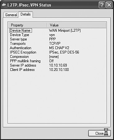
In Figure 8-53, you can see the following:
- The VPN protocol is L2TP.
- PPP is being tunneled over the L2TP tunnel.
- TCP/IP traffic is being transported over the PPP connection (IPCP has been negotiated).
- User (PPP) authentication was carried out using MS-CHAPv2.
- IPsec is being used to protect the L2TP tunnel (using ESP and 56-bit DES encryption).
- Neither compression nor Multilink PPP (MP) were negotiated.
- The VPN gateway and client (VPN tunnel interface [PPP adapter]) IP addresses are 10.10.10.69 and 10.20.10.100, respectively.
If you are unable to establish an L2TP/IPsec VPN tunnel between a remote access VPN client and a VPN gateway, you can examine logs or perform debugging on the VPN gateway (as previously discussed) and/or enable both PPP and Oakley (IKE) logging on the remote access VPN client.
If you want to enable Oakley logging on a Windows XP/2000 remote access VPN client, you need to perform the following steps:
|
Step 1. |
From the Start menu, choose Run, type regedt32.exe, and then click OK. You can now edit the registry. |
|
Step 2. |
Create a key called Oakley under HKEY_LOCAL_MACHINESystemCurrentControlSetServicesPolicyAgent. |
|
Step 3. |
Create a DWORD value under HKEY_LOCAL_MACHINESystemCurrentControlSetServicesPolicyAgentOakley called EnableLogging with a value of 1. |
Note that, as always, you should be careful when modifying the registry; in extreme cases, a mistake can make the workstation unbootable.
Figure 8-54 illustrates the creation of the DWORD value called EnableLogging with a value of 1.
Figure 8-54. Creation of the DWORD Value Called EnableLogging with a Value of 1
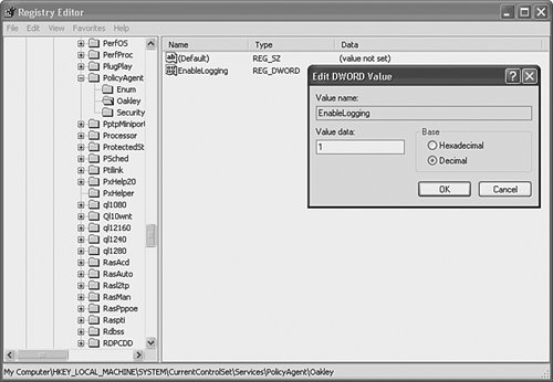
You can then find the log file itself (oakley.log) in systemrootDebug folder. The systemroot is usually the Windows folder under the C: drive.
Example 8-11 shows sample (and selected) contents of the oakley.log after VPN tunnel setup.
Example 8-11. Contents of the oakley.log After VPN Tunnel Setup
6-10: 15:02:45:406:7d0 MM PolicyName: L2TP Main Mode Policy (line 1) 6-10: 15:02:45:406:7d0 MMPolicy dwFlags 8 SoftSAExpireTime 28800 6-10: 15:02:45:406:7d0 MMOffer[0] LifetimeSec 28800 QMLimit 0 DHGroup 268435457 (line 2) 6-10: 15:02:45:406:7d0 MMOffer[0] Encrypt: Triple DES CBC Hash: SHA (line 3) 6-10: 15:02:45:421:7d0 Auth[0]:RSA Sig E=admin@mjlnet.com, C=UK, S=none, (line 4) L=London, O=MJL Network Solutions, OU=Engineering, CN=mjlnet.ca1 AuthFlags 0 6-10: 15:02:45:421:7d0 QM PolicyName: L2TP Require Encryption Quick Mode Policy (line 5) dwFlags 0 6-10: 15:02:45:421:7d0 QMOffer[0] LifetimeKBytes 250000 LifetimeSec 3600 (line 6) 6-10: 15:02:45:421:7d0 QMOffer[0] dwFlags 0 dwPFSGroup 0 (line 7) 6-10: 15:02:45:437:7d0 Algo[0] Operation: ESP Algo: Triple DES CBC HMAC: MD5 (line 8) 6-10: 15:02:45:453:7d0 Sending: SA = 0x000E58D0 to 192.168.1.1:Type 2.500 (line 9) 6-10: 15:02:45:468:7d0 ISAKMP Header: (V1.0), len = 312 (line 10) 6-10: 15:02:45:468:7d0 I-COOKIE 0b9be0cf190d6514 (line 11) 6-10: 15:02:45:468:7d0 R-COOKIE 0000000000000000 (line 12) 6-10: 15:02:45:468:7d0 exchange: Oakley Main Mode (line 13) 6-10: 15:02:45:468:7d0 flags: 0 (line 14) 6-10: 15:02:45:468:7d0 next payload: SA (line 15) 6-10: 15:02:45:468:7d0 message ID: 00000000 (line 16) 6-10: 15:02:45:468:7d0 Ports S:f401 D:f401 6-10: 15:02:45:500:7d0 Activating InitiateEvent 000005C8 6-10: 15:02:45:609:7d0 6-10: 15:02:45:609:7d0 Phase 1 SA accepted: transform=1 (line 17) 6-10: 15:02:46:703:7d0 Phase 2 SA accepted: proposal=1 transform=1 (line 18) |
Highlighted line 1 shows that L2TP has triggered the creation of an IKEv1 phase 1 (main mode [MM]) policy.
Highlighted lines 2 and 3 show one of the main mode policy proposals, which specifies 3DES encryption and the SHA-1 hashing algorithm. By default, Windows XP offers 12 IKEv1 phase 1 (main mode) policy proposals to the VPN gatewayone of these proposals must be compatible with the VPN gateway's phase 1 policies for IKEv1 phase 1 negotiation to complete successfully.
Highlighted line 4 shows that RSA digital signature (digital certificate) authentication is being used. Highlighted lines 5 shows that L2TP has triggered the creation of an IKEv1 phase 2 (quick mode [QM]) policy.
In highlighted lines 6 to 8, you can see one of the quick mode policy proposals, which specifies ESP with 3DES encryption and MD5 authentication. Windows XP offers five quick mode policy proposals by default. For IKEv1 phase 2 (quick mode) negotiation to succeed, one of the five policy proposals must be compatible with those on the VPN gateway.
Note
The Windows L2TP/IPsec remote access client does not support either IPsec tunnel mode or Authentication Header (AH). So, don't bother configuring these on the VPN gateway.
Highlighted lines 9 to 16 show an ISAKMP packet sent by the Windows XP remote access VPN client during IKEv1 phase 1 (main mode) negotiation.
In highlighted lines 17 and 18, you can see that IKE phase 1 and phase 2 SA proposals have been accepted.
Note
For much more information on troubleshooting L2TP and L2TP/IPsec, refer to Troubleshooting Virtual Private Networks (Cisco Press).
If IKE negotiation looks good, it can be useful to enable PPP logging. You can do this by entering netsh ras set tracing * enable from a command prompt on a Windows XP workstation. This command creates a file called PPP.log (as well as a number of other useful RAS-related log files such as RASCHAP.log) under the systemroot racing folder.
Example 8-12 shows sample, selected output from the PPP.log.
Example 8-12. Output from the PPP.log
[880] 15:25:28:875: [880] 15:25:28:875: Id = 0x0, (line 2) Port = 1 [880] 15:25:28:875: [880] 15:25:31:531: LCP Configured successfully (line 3) [880] 15:25:31:531: Authenticating phase started (line 4) [880] 15:25:31:531: >PPP packet received at 06/10/2005 14:25:31:531 (line 5) [880] 15:25:31:531: >Protocol = CHAP, Type = Protocol specific, Length = 0x17, Id = 0x1, Port = 1 (line 6) [880] 15:25:31:531: >C2 23 01 01 00 15 10 77 FA 0B 8F D8 31 E6 3B E1 |.#.....w....1.;.| [880] 15:25:31:531: >F5 19 2E 3F 59 6B 54 00 00 00 00 00 00 00 00 00 |...?YkT.........| [880] 15:25:31:859: >PPP packet received at 06/10/2005 14:25:31:859 (line 7) [880] 15:25:31:859: >Protocol = IPCP, Type = Configure-Req, Length = 0xc, Id = 0x0, Port = 1 (line 8) [880] 15:25:31:859: >80 21 01 00 00 0A 03 06 C0 A8 01 01 00 00 00 00 |.!..............| |
Highlighted lines 1 and 2 show that a PPP (specifically, an LCP Configure-Request) packet has been sent to the VPN gateway. LCP negotiation is underway.
In highlighted lines 3 and 4, you can see that LCP negotiation has successfully completed, and PPP authentication has begun.
Highlighted lines 5 and 6 show that a PPP CHAP packet has been sent to the VPN gateway. Much more information on the PPP authentication phase can be found in the RASCHAP.log file.
In highlighted lines 7 and 8, you can see that an IPCP Configure-Request packet has been received from the VPN gateway. IPCP negotiation is now in progress.
Configuring L2TP/IPsec Remote Access VPNs to Transit NAT Devices
If an L2TP/IPsec VPN device is present behind a NAT device, you might encounter problems establishing an L2TP/IPsec VPNs between remote access client workstations and a VPN gateway. This is because IPsec was not originally designed to operate in conjunction with Network Address Translation (NAT) devices.
Note
For much more information about the issues that you may encounter when configuring IPsec tunnels when there is a NAT device between the IPsec devices, see the section "Deploying IPsec VPNs with NAT/PAT" in Chapter 6.
As described in Chapter 6, there are various solutions when a NAT device is placed between IPsec peers, but the most popular solution is to enable NAT Traversal (NAT-T). Figure 8-55 shows how L2TP control- and data-plane packets are encapsulated when using NAT-T.
Figure 8-55. L2TP Control- and Data-Plane Packet Encapsulation When Using NAT-T

Configuring L2TP/IPsec Remote Access Clients to Support NAT-T
Windows XP Service Pack 2 includes support for NAT-T, but support for VPN gateways behind a NAT device does have to be enabled in the registry. Windows 2000 does not support NAT-T nativelyyou have to load update 818043 from the Windows update catalog at the following URL:
http://v4.windowsupdate.microsoft.com/catalog
Click Find Microsoft Windows Updates on the left, and then click Advanced Search Options. Now type 818043 in the Contain these words search box.
Note that the NAT-T update for Windows 2000 clients is designed only for a NAT traversal where a NAT device is in front of the client (not in front of the VPN gateway). To configure a Windows XP Service Pack 2 remote access VPN client to support NAT-T when a NAT device is in front of a VPN gateway, modify the registry as follows:
|
Step 1. |
From the Start menu, choose Run, type regedt32.exe, and click OK. |
|
Step 2. |
Go to HKEY_LOCAL_MACHINESYSTEMCurrentControlSetServicesIPSec. |
|
Step 3. |
Create a new DWORD value called AssumeUDPEncapsulationContextOnSendRule. |
|
Step 4. |
Modify this new DWORD value, and change its value as appropriate: - A value of 0VPN gateways behind NAT devices are not supported. - A value of 1VPN gateways behind NAT devices are supported. - A value of 2the client or VPN gateway can be behind NAT devices. |
|
Step 5. |
Click OK and reboot the Windows XP remote access client. |
As always when modifying the Windows registry, be careful; a mistake can, in extreme cases, render the workstation unbootable.
Figure 8-56 illustrates the addition of the DWORD value called AssumeUDP-EncapsulationContextOnSendRule and the modification of its value.
Figure 8-56. Addition of the DWORD Value Called AssumeUDPEncapsulationContextOnSendRule and the Modification of Its Value
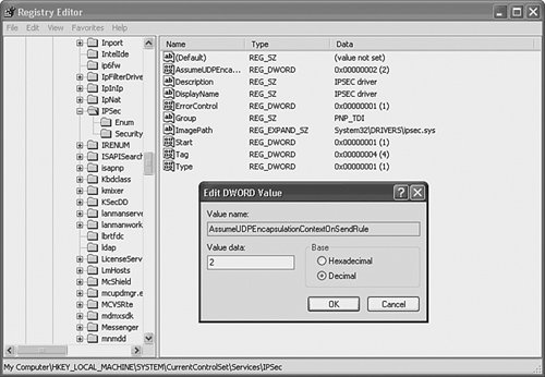
In Figure 8-56, the value of the DWORD value AssumeUDPEncapsulation-ContextOnSendRule is changed to 2.
Configuring the L2TP/IPsec VPN Gateway to Support NAT-T
The configuration of the L2TP/IPsec VPN gateway to support NAT-T is comparatively straightforwardrouters running Cisco IOS Software Release 12.2(13)T support NAT-T by default (there is no need to explicitly configure it). On Cisco VPN 3000 concentrators, you do have to explicitly configure NAT-T, and this can be accomplished by going to Configuration > System > Tunneling and Security > IPSec > NAT Transparency and checking IPSec over NAT-T (see Figure 8-57).
Figure 8-57. Enabling NAT-T on the Cisco VPN 3000 Concentrator
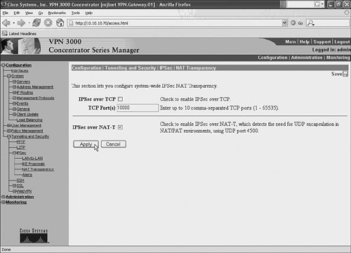
After you have checked the IPSec over NAT-T box, choose Apply, and NAT-T will be enabled.
After you have enabled NAT-T on the Windows remote access VPN clients and the VPN gateway, if they detect a NAT device, they will negotiate NAT-T, and this will allow L2TP/IPsec packets to successfully traverse the NAT device.
Ensuring That More Than One Windows L2TP/IPsec Remote Access Client Can Successfully Connect to a VPN Gateway from Behind the Same NAT Device (When Using NAT-T)
Cisco IOS Software Release 12.3(11)T4 introduced a new command (set nat demux) to ensure that more than one Windows remote access VPN client can connect to a VPN gateway when there is a NAT device in front of the Windows clients and the VPN gateway. Without configuring this command on the VPN gateway, clients might lose L2TP/IPsec connectivity to the VPN gateway.
Example 8-13 shows the configuration of the set nat demux command on a Cisco IOS VPN gateway.
Example 8-13. Configuration of the set nat demux Command on a Cisco IOS VPN Gateway
! crypto map l2tpmap 10 ipsec-isakmp profile l2tpprof set nat demux set transform-set l2tptrans ! |
As you can see, the set nat demux command is simply configured under the crypto map (which can be either static or dynamic). With the exception of the configuration of the set nat demux command, the rest of the configuration of the VPN gateway can remain the same.
The effect of the set nat demux command is to cause the Cisco IOS VPN gateway to assign a unique UDP port to each new L2TP tunnel/session that it negotiates with a remote access VPN client.
If you use the set nat demux command, the Cisco IOS VPN gateway is able to differentiate between L2TP traffic from different remote access VPN client even when the source IP address of packets is the same (which is the effect when more than one client is behind the same PAT device, and IPsec transport mode is used [as previously mentioned, tunnel mode is not supported for L2TP/IPsec on Windows machines]).
Deploying L2TP Voluntary/Client-Initiated VPNs on Cisco IOS Routers
When implementing a remote access VPN solution with L2TP, some of your telecommuters might require connectivity directly from their workstations, but some telecommuters might require connectivity from a router. In this case, you can deploy Cisco IOS L2TP client-initiated tunneling, as illustrated in Figure 8-58.
Figure 8-58. Cisco IOS L2TP Client-Initiated Tunneling
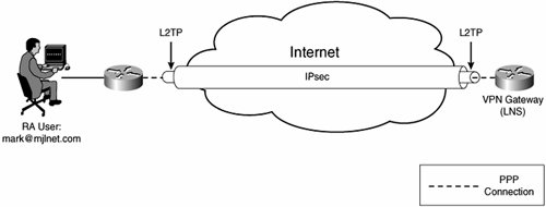
The fact that an L2TP tunnel is built from a telecommuter site router to a VPN head-end gateway makes no difference to basic L2TP tunnel setup and operationit still works as illustrated in Figure 8-6 on page 717.
When deploying Cisco IOS L2TP client-initiated tunneling, you can choose between using L2TPv2 or L2TPv3. As previously described, the main advantage of L2TPv3 over L2TPv2 is that it can tunnel many different types of payload, whereas L2TPv2 is designed to tunnel only PPP. In this case, however, the payload is PPP, and the deployment model is basic LNS to LNS (L2TPv3)otherwise known as LAC to LNS (L2TPv2)! So, L2TPv3 does not offer massive advantages over L2TPv2 in this type of deployment. The main advantage is the lower overhead (Cisco IOS L2TPv3 client-initiated tunneling uses an IP encapsulation [protocol 115] rather than a UDP/IP encapsulation).
Example 8-14 shows Cisco IOS L2TPv2 client-initiated configuration for a "client" Cisco IOS router.
Example 8-14. Cisco IOS L2TPv2 Client-Initiated Configuration for a "Client" Cisco IOS Router
! hostname mjlnet.NewYork.01 ! l2tp-class client.init.class (line 1) authentication (line 2) password 7 02050D480809 (line 3) ! pseudowire-class client.init.pw (line 4) encapsulation l2tpv2 (line 5) protocol l2tpv2 client.init.class (line 6) ip local interface Ethernet0 (line 7) ! username mjlnet.London.Gateway.03 password 7 094F471A1A0A (line 8) username mjlnet.NewYork.01 password 7 14141B180F0B (line 9) ! interface Ethernet0 ip address 10.2.1.1 255.255.255.0 ! interface Virtual-PPP1 (line 10) ip unnumbered Ethernet0 (line 11) no cdp enable (line 12) ppp authentication chap (line 13) pseudowire 10.40.10.1 1001 pw-class client.init.pw (line 14) ! ip route 10.10.10.0 255.255.255.0 Virtual-PPP1 (line 15) ! |
A quick look at the configuration in Example 8-14 reveals that it is pretty similar to that for LAC-to-LAC pseudowires (see Chapter 2). In this case, however, the L2TP model used is LNS to LNS (because the PPP connection is terminated on both peers), and there are therefore one or two important differences in the configuration.
The l2tp-class l2tp-class-name in highlighted line 1 configures an L2TP class. This can be used to configure L2TP control-plane parameters, and in this case it is used to configure L2TP authenticationthe authentication command (highlighted line 2) enables L2TP authentication, and the password password command (highlighted line 3) is used to specify the password used for L2TP authentication.
Highlighted lines 4 to 7 show the configuration of a pseudowire class. This is used to configure parameters such as data- and control-plane encapsulation types as well as source IP address.
In highlighted line 4, the pseudowire-class pw-class-name command is used to configure a pseudowire class called client.init.pw.
The encapsulation {l2tpv2 | l2tpv3 | [manual]} command (highlighted line 5) specifies the data-plane encapsulation, which in this case is L2TPv2.
The protocol {l2tpv2 | l2tpv3 | none} {l2tp-class-name} command (highlighted line 6) configures the control-plane protocol and links to an L2TP class. The control-plane protocol is configured as L2TPv2, and a link is specified to the L2TP class called client.init.class (configured in highlighted lines 1 to 3).
The username username password password commands in highlighted lines 7 and 8 are used to configure the usernames and passwords to be used for PPP authentication between the peer routers.
Highlighted lines 9 to 13 show the configuration of interface virtual-PPP 1. The PPP connection is terminated on this interface.
The ip unnumbered interface-name command (highlighted line 10) "borrows" the IP address configured on interface Ethernet 0 for use on interface virtual-PPP 1.
The no cdp enable command (highlighted line 11) is then used to disable CDP on the interface, and ppp authentication chap (highlighted line 12) is used to enable CHAP authentication.
In highlighted line 13, the pseudowire peer-ip-address vc pw-class pw-class-name command configures the remote endpoint of the L2TP tunnel (the VPN head-end gateway), as well as the pseudowire class name (configured in highlighted lines 4 to 7). The virtual circuit (VC) number specified using the pseudowire command is irrelevant to the configuration of L2TPv2 (specify any VC number you want!).
Finally, in highlighted line 14, the ip route command configures a route to a remote network at the VPN head-end gateway site via the virtual-PPP interface.
Example 8-15 shows the configuration of the VPN head-end gateway.
Example 8-15. Configuration of the VPN Head-End Gateway
! hostname mjlnet.London.Gateway.03 ! username mjlnet.London.Gateway.03 password 7 094F471A1A0A (line 1) username mjlnet.NewYork.01 password 7 14141B180F0B (line 2) ! vpdn enable ! vpdn-group 1 accept-dialin protocol l2tp virtual-template 1 terminate-from hostname mjlnet.NewYork.01 l2tp tunnel password 0 cisco (line 3) ! ! interface Loopback100 ip address 10.30.10.1 255.255.255.0 ! ! interface FastEthernet2/0 ip address 10.40.10.1 255.255.255.0 ! ! interface Virtual-Template1 ip unnumbered Loopback100 no peer default ip address (line 4) ppp authentication chap ! |
If you compare the configuration shown in Example 8-15 to that shown in Example 8-4 on page 733, you will see that they are almost identical.
The only real differences are the fact that L2TP authentication is configured using the l2tp tunnel password password command (highlighted line 3), and no IP address is assigned to the remote access client (mjlnet.NewYork.01 in this case) because the no peer default ip address command is configured under the virtual template interface.
In fact, because PPP authentication is configured between the peers, you do not absolutely need L2TP authentication. And if you want to, you can dynamically assign IP addresses to the remote access clients using the peer default ip address command (highlighted line 4).
Highlighted lines 1 and 2 shows the username and passwords used for PPP authentication.
You can use a number of commands to verify L2TPv2 client-initiated tunneling on the head-end VPN gateway, including show vpdn session, show vpdn tunnel, and show caller user. Example 8-16 shows the output of the show vpdn tunnel command on mjlnet.London.Gateway.03.
Example 8-16. show vpdn tunnel Command Output for mjlnet.London.Gateway.03
mjlnet.London.Gateway.03#show vpdn tunnel %No active L2F tunnels L2TP Tunnel Information Total tunnels 1 sessions 1 (line 1) LocID RemID Remote Name State Remote Address Port Sessions L2TP Class/ VPDN Group 60057 1715 mjlnet.NewYor est 192.168.3.1 1701 1 1 (line 2) %No active PPTP tunnels mjlnet.VPN.Gateway.03# |
Highlighted line 1 shows that 1 L2TP tunnel and 1 L2TP session have been established.
Highlighted line 2 shows information including the name of the remote peer (mjlnet.NewYork.01), the IP address of the remote peer (192.168.3.1), the tunnel (UDP) port (1701, L2TP).
Example 8-17 shows the output of the show caller user command on mjlnet.London.Gateway.03.
Example 8-17. show caller user Command Output for mjlnet.London.Gateway.03
mjlnet.VPN.Gateway.03#show caller user mjlnet.NewYork.01 User: mjlnet.NewYork.01, line Vi2.1, service PPPoVPDN (line 1) Connected for 00:07:07, Idle for 00:07:05 Timeouts: Limit Remaining Timer Type - - - PPP: LCP Open, CHAP (<-->), IPCP (line 2) IP: Local 10.30.10.1, remote 10.2.1.1 (line 3) Counts: 85 packets input, 1348 bytes 89 packets output, 1478 bytes mjlnet.VPN.Gateway.03# |
Highlighted line 1 shows the username (mljnet.NewYork.01), the interface on which the PPP connection is terminated (interface virtual access 2.1) and the service (PPP tunneled over a VPDN protocol [L2TP]).
In highlighted line 2, you can see that LCP is established (Open), that CHAP authentication takes places in both directions over the tunnel (look at the arrowseach peer authenticates the other), and that IPCP has been negotiated between the peers (IP is being transported).
Highlighted line 3 shows the local and remote IP addresses. These IP addresses are those applied to the virtual-PPP and virtual-template (virtual access) interfaces and are passed between the peers during IPCP negotiation.
So much for L2TPv2 client-initiated tunnel mode. How about L2TPv3 client-initiated tunnel mode? Example 8-18 shows sample configurations using L2TPv3.
Example 8-18. Sample Configurations for Client-Initiated Tunneling with L2TPv3
!
hostname mjlnet.NewYork.01
!
username mjlnet.London.Gateway.03 password 7 094F471A1A0A
username mjlnet.NewYork.01 password 7 14141B180F0B
!
l2tp-class client.init.class
authentication
 password 7 02050D480809
!
pseudowire-class client.init.pw
 encapsulation l2tpv3
 protocol l2tpv3 client.init.class
 ip local interface ethernet0
!
interface Virtual-PPP1
 ip unnumbered loopback1
 ppp authentication chap
 pseudowire 10.40.10.1 1000 pw-class client.init.pw
!
ip route 10.10.10.0 255.255.255.0 Virtual-PPP1
hostname mjlnet.London.Gateway.03 ! username mjlnet.London.Gateway.03 password 7 094F471A1A0A username mjlnet.NewYork.01 password 7 14141B180F0B ! l2tp-class client.init.class authentication password 7 02050D480809 ! pseudowire-class client.init.pw encapsulation l2tpv3 protocol l2tpv3 client.init.class ip local interface ethernet0 ! interface Virtual-PPP1 ip unnumbered loopback100 ppp authentication chap pseudowire 192.168.3.1 1000 pw-class client.init.pw ! ip route 10.2.1.0 255.255.255.0 Virtual-PPP1 ! |
As you can see, the configuration of mjlnet.NewYork.01 greatly resembles that when using L2TPv2 (see Example 8-14). The key difference is that the encapsulation and protocol commands within the pseudowire class now specify L2TPv3 rather than L2TPv2.
The configuration of mjlnet.London.Gateway.03 is radically different when using L2TPv3 (compare with Example 8-15). The commands used are now the same as those used for the configuration of mjlnet.NewYork.01the only difference being the IP addresses used.
Part I: Understanding VPN Technology
What Is a Virtual Private Network?
- What Is a Virtual Private Network?
- VPN Devices
- Deploying Site-to-Site and Remote Access VPNs: A Comparison
- Summary
- Review Questions
Part II: Site-to-Site VPNs
Designing and Deploying L2TPv3-Based Layer 2 VPNs
- Designing and Deploying L2TPv3-Based Layer 2 VPNs
- Benefits and Drawbacks of L2TPv3-Based L2VPNs
- L2TPv3 Pseudowire Operation
- Configuring and Verifying L2TPv3 Pseudowires
- Summary
- Review Questions
Designing and Implementing AToM-Based Layer 2 VPNs
- Designing and Implementing AToM-Based Layer 2 VPNs
- Benefits and Drawbacks of AToM-Based L2VPNs
- AToM Pseudowire Operation
- Deploying AToM Pseudowires
- Implementing Advanced AToM Features
- Summary
- Review Questions
Designing MPLS Layer 3 Site-to-Site VPNs
- Designing MPLS Layer 3 Site-to-Site VPNs
- Advantages and Disadvantages of MPLS Layer 3 VPNs
- MPLS Layer 3 VPNs Overview
- A Detailed Examination of MPLS Layer 3 VPNs
- Deploying MPLS Layer 3 VPNs
- Summary
- Review Questions
Advanced MPLS Layer 3 VPN Deployment Considerations
- Advanced MPLS Layer 3 VPN Deployment Considerations
- The Carriers Carrier Architecture
- The Inter-Autonomous System/Interprovider MPLS VPN Architecture
- Supporting Multicast Transport in MPLS Layer 3 VPNs
- Implementing QoS for MPLS Layer 3 VPNs
- Supporting IPv6 Traffic Transport in MPLS Layer 3 VPNs Using 6VPE
- Summary
- Review Questions
Deploying Site-to-Site IPsec VPNs
- Deploying Site-to-Site IPsec VPNs
- Advantages and Disadvantages of IPsec Site-to-Site VPNs
- IPsec: A Security Architecture for IP
- Deploying IPsec VPNs: Fundamental Considerations
- Summary
- Review Questions
Scaling and Optimizing IPsec VPNs
- Scaling and Optimizing IPsec VPNs
- Scaling IPsec Virtual Private Networks
- Ensuring High Availability in an IPsec VPN
- Designing QoS for IPsec VPNs
- MTU and Fragmentation Considerations in an IPsec VPN
- Summary
- Review Questions
Part III: Remote Access VPNs
Designing and Implementing L2TPv2 and L2TPv3 Remote Access VPNs
- Designing and Implementing L2TPv2 and L2TPv3 Remote Access VPNs
- Benefits and Drawbacks of L2TP Remote Access VPNs
- Operation of L2TP Voluntary/Client-Initiated Tunnel Mode
- Implementing L2TP Voluntary/Client-Initiated Tunnel Mode Remote Access VPNs
- Designing and Implementing L2TP Compulsory/NAS-Initiated Tunnel Mode Remote Access VPNs
- Integrating L2TP Remote Access VPNs with MPLS VPNs
- Summary
- Review Questions
Designing and Deploying IPsec Remote Access and Teleworker VPNs
- Designing and Deploying IPsec Remote Access and Teleworker VPNs
- Comparing IPsec Remote Access VPNs with Other Types of Remote Access VPNs
- Understanding IKE in an IPsec Remote Access VPN Environment
- Deploying IPsec Remote Access VPNs Using Preshared Key and Digital Signature Authentication
- Summary
- Review Questions
Designing and Building SSL Remote Access VPNs (WebVPN)
- Designing and Building SSL Remote Access VPNs (WebVPN)
- Comparing SSL VPNs to Other Types of Remote Access VPNs
- Understanding the Operation of SSL Remote Access VPNs
- Using Clientless SSL Remote Access VPNs (WebVPN) on the Cisco VPN 3000 Concentrator
- Implementing Full Network Access Using the Cisco SSL VPN Client
- Strengthening SSL Remote Access VPNs Security by Implementing Cisco Secure Desktop
- Enabling SSL VPNs (WebVPN) on Cisco IOS Devices
- Deploying SSL VPNs (WebVPN) on the ASA 5500
- Summary
- Review Questions
Part IV: Appendixes
Designing and Building SSL Remote Access VPNs (WebVPN)
- Designing and Building SSL Remote Access VPNs (WebVPN)
- Appendix A. VPLS and IPLS Layer 2 VPNs
- Understanding VPLS
- Understanding IPLS
- Summary: Comparing VPLS and IPLS
Appendix B. Answers to Review Questions
EAN: 2147483647
Pages: 124
