Computer Network Software
Computer NetworkSoftware
In this chapter, you will learn about
- Network types
- Network operating systems
- Network protocols
- Network security measures
- Network addressing
The networking hardware discussed in Chapter 11 establishes the network in its physical sense, but without networking software, the network has no life. Networking software prepares and presents data to the media for transmission. At the other end of the media, software intercepts, formats, and presents the data to a computer for processing. When the response is ready, the software performs its tasks to deliver the data to the requesting PC and assists the PC to display the data for the user. Without several types of network software, none of that would happen.
In this chapter, we explore the elements of software that combine with the hardware to make a network function. I discuss protocols, the NOS (Network Operating System), and a series of networking utilities that can help you to test, debug, and troubleshoot a network, large or small.
Software and the Network
As networking has become more popular, even in the home, the software tools available have made the task of installing and configuring network software relatively easy. Network operating systems, such as Windows 2000, Windows XP, or Mac OS X, have made the task of configuring a network logically a fairly simple matter.
The general classifications of network software are as follows:
- Network operating systems (NOS)An NOS, on the whole, operates outside of the OSI model. Typically, an NOS is installed on a network server and used to manage and control the network resources. Most NOS packages provide their strongest support to the network at the Application layer. I’ll talk again about the NOS when I discuss the client/server relationship later in this chapter. Some examples of NOS that can be used to manage a home network are Windows NT 4.0, Windows 2000 Professional, Windows XP Professional, Mac OS X, and Windows 2003, which is perhaps an overkill for a home network.
- Network protocolsIn the Internet environment, one group or suite of protocols is dominant, almost to the exclusion of any other protocol suite: Transmission Control Protocol/Internet Protocol or TCP/IP, as it is more commonly known. A protocol is a set of rules that must be obeyed by the parties in a communication, whether it is on the phone, across the fence, or over a network. Without protocols, or a set of rules, data transmission would be chaos.
Included in the TCP/IP protocol suite are a group of utilities (software programs) that can be the network technician’s best friend when a networked PC is having trouble communicating on the network.
- Network security softwareArguably, this group of software is very important, especially in the days of “always on” network connections and the demonstrated skill level and number of evildoers out there on the Internet.
Network Operating Systems
The primary purpose of a network operating system (NOS) is to provide for centralized control and management of a network and its resources. In the early days of networking, nearly all networks were peer-to-peer arrangements, where every user was the administrator of his or her part of the network. But, as networks have grown, especially in size and their ability to interoperate, centralized administration of the network has become a virtual necessity.
Peer-to-Peer Networks
Each computer on a peer-to-peer network is directly connected to the computers before and after it in a daisy-chained fashion. The purpose of a peer-to-peer network, like any type of network, is to share resources. However, on a peer-to-peer network, the resources are owned and controlled by the individual users (owners) of the PCs that make up the network. Obviously, this arrangement requires some cooperation and sharing among the network users to succeed.
Figure 12-1 depicts a very simple two-computer peer-to-peer network structure. On this network, one user has a nifty new laser printer and the other controls the access to the Internet through a modem. If User1 wishes to allow User2 to access and use his or her laser printer, he or she must grant permission to User2 to do so. The same goes for User2 allowing User1 access to the Internet connection via the modem.
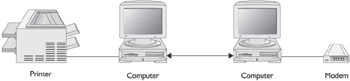
Figure 12-1: A two-computer peer-to-peer network sharing a printer and a modem
Peer-to-peer networks are very common in home networking situations because the PCs are in relatively close proximity and the number of computers is typically much fewer than 8 to 10. Above this range, the administration of the individual computers is more efficient if transferred to a centralized activity.
Commonly, a home peer-to-peer network is created by installing a network adapter in each PC and connecting the computers to one another using Cat 5 wire and RJ-45 connections (see Chapters 1 and 2 for information on these networking elements).
| Tip |
The EIA/TIA 568b cable (see Chapter 11) used to connect two network adapters directly is called a rolled cable, which means its receive and transmission lines are crossed over to directly interface to each other. |
A peer-to-peer network doesn’t require an NOS. Most client operating systems, such as Windows 9x, Windows NT Workstation, Windows 2000 Pro, Windows XP Pro, and Windows Me, all include features that support peer-to-peer networking and file, print, and other resource sharing.
Client/Server Networks
The type of network most commonly found in a business setting is a client/server network. The elements of this network include the network client, which formulates and sends requests to a server for information and the use of software or hardware, and the server, which interprets and responds to the requests from the clients. Just like in a restaurant, we are the clients and the server is, well, the server.
Client/server networks are built on a network structure that includes one or more centralized servers. In the context of client/server, a server is a piece of software that runs on a centralized hardware “server.” We might have a fax server, an e-mail server, a database server, and most likely a web server on our network. In fact, as is the case on most networks, there is probably only a single computer on which all or at least most of the server software is running.
Ethernet networking is very popular on client/server networks. Understand that client/server networks are actually topology-independent. It really doesn’t matter how the network is shaped or configured, as long as at any given time, clients can request services from servers.
Both the Mac OS and Windows Server operating systems include embedded support for client/server networking, including some advanced functions I’ll discuss a bit later in this chapter. However, a full-blown NOS is often overkill for home networking requirements. There is no doubt that a full NOS will work, but there are the issues of tool-to-the-task and cost.
Network Protocols
A network protocol is a set of rules that govern the interactions between two communicating entities, regardless of whether they are two computers, modems, routers, or other hardware or software. When one modem dials up another, the transmissions between them are governed by a common protocol. The same goes for two computers on a peer-to-peer network or two routers on a wide area network (WAN).
The Transmission Control Protocol/Internet Protocol (TCP/IP) suite includes a collection of communications and networking protocols that can be used to initiate, facilitate, manage, maintain, and troubleshoot network communications, whether on a local area network (LAN) or a WAN.
The best way to understand the purpose and application of the TCP/IP protocols is by their function. Table 12-1 groups the TCP/IP protocols by their general function or when they are applied, and the OSI layer each operates on.
|
Function |
Protocol |
OSI Layer |
|---|---|---|
|
Application interface |
Domain Name System (DNS) Dynamic Host Configuration Protocol (DHCP) File Transfer Protocol (FTP) Hypertext Transfer Protocol (HTTP) Internet Mail Access Protocol (IMAP) Post Office Protocol, ver. 3 (POP3) Simple Mail Transfer Protocol (SMTP) |
Application and Presentation |
|
Transmission of data |
Transmission Control Protocol (TCP) User Datagram Protocol (UDP) |
Transport |
|
Addressing and delivery |
Internet Protocol (IP) Internet Control Message Protocol (ICMP) Packet Internet Groper (PING) Trace Route (TRACERT) |
Network |
Here is a brief description of each of these protocols:
- DNS: The TCP/IP service used to convert human-friendly domain names (such as comptia.org) to their IP address equivalents (such as 10.0.100.20).
- DHCP: This protocol is used to automatically configure a networked PC each time the PC is booted (powered on or restarted). DHCP provides an IP address and other TCP/IP configuration data to enable a PC to connect and interact with its network.
- FTP: Used to transfer entire files from one computer to another over the Internet.
- HTTP: Defines how requests and response messages are formatted and transmitted and the actions web servers and browser software take in response to the commands included in the transmitted messages and files. S-HTTP (or HTTPS) is an extension of HTTP that provides for secure transmission of data.
- ICMPOther protocols and devices that need to communicate with one another use this protocol.
- IMAPA protocol that allows e-mail to be accessed and read on a mail server and optionally transferred to a mail client.
- IPThe workhorse protocol of the Internet, IP defines logical addressing (IP addresses) and how it is applied to networks and hosts across a network.
- PINGUsed to verify that two network nodes are able to communicate with each other.
- POP3A protocol used to move e-mail from a mail server to a mail client.
- SMTPThe protocol used to transfer e-mail messages between mail servers.
- TCPA connection-oriented protocol that manages the transmission of data between two communicating stations. TCP includes processes that provide for reliable, guaranteed transmission and receipt of data between a source address and a destination address. TCP messages must be acknowledged as received before additional messages are sent.
- TRACERT Used to determine the routing path used by messages to move across a network from a source address to a destination address.
- UDP A connectionless protocol that transports messages across a network without mechanisms to provide for reliability or delivery guarantees. UDP messages are not acknowledged and are transmitted in a continuous stream.
Network Security
Security is perhaps the most important issue surrounding the use of networks. Security is a growing concern on all types of networks, whether they are small networks in homes and offices, or large international networks, such as the Internet.
Included in the TCP/IP protocol suite are a few utilities that help to create a secure environment for a home network. Most of the Internet gateways (modems, bridges, or routers) used with broadband communication services also provide services to help secure the devices attached to them. In addition, third-party software and hardware can be added to a home network to provide additional security.
TCP/IP Security
When a homeowner subscribes to an Internet service, the Internet service provider (ISP) provides the connection with an IP address. This address is assigned to the connection using DHCP and the IP address assigned will typically be different each time the user connects to the ISP’s network. Dynamic addresses (those that change frequently) create a moving target for a network hacker looking to invade a home network. However, DHCP alone isn’t enough to prevent an intrusion.
NAT
A home that has subscribed to either cable or DSL must use an Internet gateway device to connect to the service. Many of these devices have switching or routing capabilities. This is good news in terms of network security.
The Network Address Translation (NAT) protocol is supported by most of the Internet gateways used by cable and DSL services. Even most dialup connections are protected behind a router (at the ISP) that is running NAT services.
What NAT does is translate the IP address of a computer on its internal network into a generic one that is sent out over the external network. This way, anyone wishing to access a specific network computer has only the generic IP address issued by the NAT device and not the IP address of a particular computer.
Private IP Addresses
Within the grand scheme of IP addressing, three blocks of addresses are set aside for use on private networks (see Table 12-2). A private network is one where the networked devices are behind an Internet gateway (usually a router) and don’t interact with the Internet directly. On the other hand, a public network is a network like the Internet, where all of the devices are able to communicate directly with one another, such as one router transmitting to another.
|
IP Address Class |
Private IP Address Range |
|---|---|
|
Class A |
10.0.0.0 to 10.255.255.255 |
|
Class B |
172.16.0.0 to 172.31.255.255 |
|
Class C |
192.168.0.0 to 192.162.255.255 |
Because the Internet world has not converted to the much larger addresses of IP version 6, IP version 4 addresses (there was no real version 5) are now in short supply and as a result most Internet subscribers are issued only one or two IP addresses or are assigned an address through DHCP. Well, if a home network has four computers and a printer to address, using one IP address (and a dynamic one no less) just won’t work. This problem is solved using NAT.
Using one of the private IP address blocks (see Table 12-2), each workstation and peripheral device on a home network can be assigned its own private network address. NAT, running on the Internet gateway, converts the private address to a generic public address that is broadcast to the external network. Don’t worry—IP addressing and the address classes are covered a bit later in this chapter.
Access Lists
Another feature that may be available in the Internet gateway device is access lists. They are also called access control lists (ACLs). ACLs use a feature called packet filtering to scan the source and destination addresses included in network messages to determine if the sender has the authority or permission to send messages to the destination address—that is, if it can access the network at all.
When a packet-filtering device receives message packets from either an internal or an external source, it extracts the IP address of the sending station (source address) and compares it to an access control list created by the network administrator (the homeowner, in the HTI+ world). Depending on the action prescribed by the information on the list, the message is either permitted access in or out or denied access in or out.
Firewall
Internet gateways also provide basic firewall functions. A firewall works something like an access control list in that it performs packet filtering to deny access to a PC from external sources. However, on a firewall the filtering can occur on the type of application being accessed or the type of action requested, such as chat, e-mail, ftp, and so on.
Wireless Security
The primary security protocol on a wireless or 802.11b wireless gateway or access point is Wired Equivalent Privacy (WEP). Wireless (802.11b) gateways implement the WEP protocol to provide transmission security for wireless networks. WEP encrypts data sent between computers and other devices on a wireless LAN using either 40-bit or 128-bit encryption. Running WEP at all times on home networks running on a wireless platform ensures the security of the data transmissions.
Wireless networks shouldn’t be operated without some type of security function in place. The most common type is encryption, which is what protocols such as WEP provide. WEP, or whatever security protocol is to be used, must be set up on the wireless router or gateway device. This setup varies by manufacturer, so reference the router’s or gateway’s documentation for the setup procedure.
Network Addressing
Addressing is a very important part of networking. Just as a house or building must have an address so that postal and package services and friends and relatives can find it, each node on a network must also have a unique address. In fact, on a network, most nodes actually have at least two addresses: a logical address and a physical address.
On every street in every town, each building, office, and house has a single mailing address that uniquely identifies it. In the same way, each node on a network must also be uniquely identified, and for just the same reason. In our society, even people can be identified in a number of different ways, including Social Security number, phone number, driver’s license number, and home address.
A networked computer is also identified with a variety of physical and logical addresses, including its Media Access Control (MAC) address, Internet Protocol (IP) address, and perhaps a Uniform Resource Locator (URL). For example, a networked computer can have an IP address, such as 172.168.10.10, for use on IP networks, a MAC address, such as 00-A0-CC-34-0A-CE, for use on a local network, and a URL, such as http://www.rongilster.com, so people can find its web page.
Logical versus Physical Addressing
IP addresses are logical addresses because each address is created in a logical pattern that ties one network device to others on the same network. What this means is that it is safe to assume that a networked device with an IP address of 192.168.20.15 is logically located on the same segment of a network as the device with the IP address of 192.168.20.14. IP addresses tend to be assigned in a series, one at a time, in a logical pattern. On the other hand, physical addresses are random.
Physical Addresses
When a networking device is manufactured, it is assigned a physical address that is a universally unique identification number permanently embedded in its electronic circuitry. This number, known as a Media Access Control, or MAC, address is like a lifetime membership card to the networking club. On local networks, the MAC address is used to route messages to specific devices. In essence, a MAC address is the unique identifying number assigned to each network adapter or other networking device. MAC addresses are physical addresses.
A MAC address consists of a 48-bit or 6-byte hexadecimal number. It is represented in the form of six two-digit numbers separated by dashes. The first 24 bits (3 bytes) of the MAC address contain a code assigned by the IEEE (The Institute of Electrical and Electronics Engineers) to uniquely identify the manufacturer of the card, and the 24 bits (3 bytes) are a number uniquely assigned by the manufacturer. For example, a MAC address of 00-A0-CC-34-0A-CE includes a manufacturer ID number of 00-A0-CC and a serialized ID number of 34-0A-CE. The segments of this number are hexadecimal numbers, but their specific values aren’t important, only their uniqueness.
Every networked computer has a MAC address—the address burned into its network adapter during manufacturing. On a Windows PC, the MAC address assigned to its network adapter can be displayed using the TCP/IP command IPCONFIG that should look something like the display shown in Figure 12-2. On this computer, the MAC address is listed as the Physical Address.
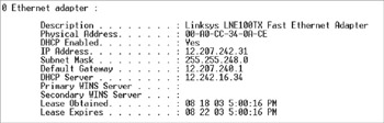
Figure 12-2: The display produced by the IPCONFIG command
Logical (IP) Addresses
The most commonly used logical network address is what is called an IP address. It gets its name from the Internet Protocol (IP), which controls and manages logical addressing on TCP/IP networks, both small (like a home network) and large (like the Internet).
IP addresses are 32 bits long (the equivalent of 4 bytes) and are represented as four 8-bit segments, called octets, that are arranged into a dotted-decimal notation scheme, as in 100.100.100.100.
| Note |
The latest version of IP addressing to emerge is IP version 6 (IPv6), which provides a 128-bit address and supports a more complex numbering scheme than the currently popular IP version 4 (IPv4). IPv6 is backward compatible for IPv4, so don’t worry too much about support for IPv6 in a home network. |
Binary Address Representation
Although IP addresses are represented in decimal numbers for human readability purposes, computers and networking devices see these addresses as a series of binary bits. The binary number system uses only two values (0 and 1) to represent numbers in powers of 2.
Most people are accustomed to thinking and working in the decimal system, which is based on the number 10. To most people, the number 124 represents 100 + 20 + 4. To the computer, this number of 124 is 1111100, which is 64 (26) + 32 (25) + 16 (24) + 8 (23) + 4 (22) + 0 (21) + 0 (20). Each position in a binary number represents, right to left, a power of two beginning with 20 and increasing by one power of two as it moves left: 20, 21, 22, 23, 24, and so forth.
Perhaps we need a quick lesson in binary-to-decimal conversion. There are 8 bits in an octet, and each bit can only be a 1 or a 0. The highest binary number that can be expressed in an octet is 11111111. To convert this binary number to its decimal equivalent requires that we know the powers of two value of each position that has a 1, which in this case is all of them. The powers of two values for the 8 bits in an octet are
2726252423222120
When a 1 is placed in one of the binary positions, it means that the value of that position adds into the decimal value being represented. A zero (0) in any position indicates that the value of that position is not added into the decimal value.
To convert a binary octet that has all 1s, use Table 12-3 as a guide to convert the values assigned to each position in an octet into the total decimal value being represented.
|
Binary Positional Value |
27 |
26 |
25 |
24 |
23 |
22 |
21 |
20 |
|
Decimal Value |
128 |
64 |
32 |
16 |
8 |
4 |
2 |
1 |
Using the information in Table 12-3, the binary number 11111111 converts into a decimal value by adding up the individual values of each position, as
128 + 64 + 32 +16 + 8 + 4 + 2 + 1 = 255
This means that the largest decimal number that can be represented in an IP address octet is 255. This is important information for reasons I will discuss a bit later in this chapter. In the same manner, the decimal number 196 would be represented in an octet as 11000100 or
128 + 64 + 0 + 0 + 0 + 4 + 0 + 0 = 196
IP Address Classes
IP addresses are divided into five address classes; each is designated with a letter A to E. Classes D and E are not used for general IP addressing. Class D addresses are used for multicasting (or broadcasting a message or an audio/video stream to a preset list of addresses) and Class E addresses are reserved for testing and future, reserved usage. Table 12-4 lists the IP address ranges included in Classes A, B, and C.
|
Class |
Value in the First Octet |
|---|---|
|
Class A |
0–127 |
|
Class B |
128–191 |
|
Class C |
192–223 |
Using the ranges in Table 12-4, the address class of an IP address can be determined by the value in its first octet. For example, an address with 120 in the first octet is a Class A address; an address with 155 in the first octet is a Class B address; and an address with 220 in its first octet is a Class C address. As I discuss later in the chapter, knowing the address class of an IP address is key to setting subnet masks, if needed.
Networks and Hosts
The 32 bits and 4 octets of an IP address represent network and host IDs. The number of bits or octets used depends on the IP address class of the IP. Table 12-5 lists how each IP address class designates which octets are a part of which ID, network or host.
|
Class |
Octet1 |
Octet2 |
Octet3 |
Octet4 |
|---|---|---|---|---|
|
Class A |
Network |
Host |
Host |
Host |
|
Class B |
Host |
Host |
Network |
Network |
|
Class C |
Network |
Network |
Network |
Host |
In the IP addressing scheme, every network is assigned a network address and every node, device, or interface (such as a switch, bridge, or router port) is assigned a host address. In Figure 12-2 shown earlier in the chapter, the IP address assigned to that computer was 12.207.232.21. Based on what we know to this point, we can assume that this is a Class A address and the network address is 12.0.0.0 (zeroes are used as placeholders) and the host ID portion is 207.232.21 on network 12.0.0.0.
Assigning Network Addresses
In a home networking situation, the Internet service provider (ISP), which provides the Internet connection, assigns one IP address to each subscriber. Typically, this address is a dynamic address and may be different each time a connection is made to the ISP’s network. In some situations, such as in high-speed Internet connections, a static (permanent and unchanging) IP address may be assigned.
In a home network situation with, for example, four computers sharing the Internet connection, each of the computers must be assigned a unique IP address in order to communicate with the Internet gateway device (to which the IP address from the ISP is actually assigned). Typically, the address assigned by the ISP will be either a Class C address or a subnet equivalent (more on subnets later in the chapter). This may appear to present a problem, but the IP addressing specifications have made provisions for these situations through what are called private addresses.
Special Addresses
The IP address specifications set aside some addresses for use in special situations. These addresses fall into four categories:
- Network addresses: Any IP address where the host ID portion of the address is all zeroes is a network address and cannot be assigned to a host or node on a network.
- Broadcast addresses: Any IP address where the host ID portion of the address is all ones is a broadcast address and cannot be assigned to a host or node on a network. Broadcast addresses are used to send a variety of messages to all nodes on a network.
- Loopback testing: The address range 127.0.0.0 to 127.255.255.255 (the entire 127 address range) is reserved for loopback testing on any network. Loopback testing is used to test the connection and functionality of a network adapter.
- Private network addresses: Three address ranges have been set aside for use by private networks, those behind an Internet gateway device or those that don’t connect to the Internet. Table 12-6 lists the private address ranges that have been reserved for this use. Each of the computers and networked devices on a home network is assigned an IP address from one of these ranges. The range that is used is actually a matter of choice in a home networking situation because each range has enough available addresses for virtually every home networking situation.
Table 12-6: Private Addresses IP Class
Address Range
Class A
10.0. 0.0 through 10.255.255.255
Class B
172.16.0.0 through 172.31.255.255
Class C
192.168.0.0 through 192.168.255.255
Subnet Masks
As mentioned earlier, an IP address has two parts: the network identification portion and the host identification portion. In order to route an address across a network, the network and host portions of the address must be separately identified. In most cases, if you know the address class, it’s easy to separate the two portions.
The function of a subnet mask is to extract the network ID portion of an IP address. This function is performed, in the case of a home network, by the Internet gateway device to determine whether an IP address is on the local network or whether it must be routed outside the local network—to the Internet, for example.
Table 12-7 lists the default subnet masks for Class A, B, and C addresses.
|
Address Class |
Subnet Mask |
|---|---|
|
A |
255.0.0.0 |
|
B |
255.255.0.0 |
|
C |
255.255.255.0 |
Without going into the Boolean algebraic functions that are used when a subnet mask is applied, the value 255 in an octet indicates the portion of the IP address that is used for the network ID. So, using the information in Table 12-7, a Class A address uses one octet, a Class B address uses two octets, and a Class C address uses three octets for the network ID.
Review
The software building blocks of a home network are the network operating system (NOS), the network protocols, and the network security software. The purpose of the NOS is to provide for centralized control and management of a network and its resources. Network protocols provide the rules and guidelines that govern the transmission of data between two communicating entities. Security features, whether implemented through software or features of the networking hardware, prevent unauthorized users from accessing the network as well as protect data transmission around wired and wireless networks.
The two types of network structures are peer-to-peer and client/server. Peer-to-peer is the most commonly used type for home networks. Star topology-based networks are also common.
TCP/IP is the most commonly used protocol suite on local area networks (LANs) and wide area networks (WANs). Included in this protocol suite are protocols that perform virtually every step in the process used to transmit data across a network, including DNS, DHCP, HTTP, POP3, PING, and TRACERT.
Network security is applied to a home network through several tools. First, the ISP provides some level of security. However, at the home network location, security must be applied through such tools as DHCP, NAT, private IP addresses, access lists, a firewall, and security protocols such as WEP (for wireless networks).
On TCP/IP networks, there are two types of addressing: logical and physical. An IP address is a logical address. Each network device has a universally unique MAC address embedded into its electronics during manufacturing. DNS is used to resolve domain names to their IP address equivalents.
An IP address is expressed in four 8-bit octets. IP addressing is divided into address classes A, B, and C. Within the address classes, a range of addresses have been set aside for use by private networks. An IP address is made up of network and host IDs. A subnet mask is used to extract the network ID from an IP address.
Questions
- What type of network system software manages and controls a network’s resources?
- Database management software
- Network protocols
- Network security software
- Network operating system
- A specification of the rules and guidelines that govern the transmission of data between two communicating entities is called a
- Session
- Connection
- Protocol
- Handshake
- Which two of the following are common network implementations in home networks?
- Mesh
- Peer-to-peer
- Star-based Ethernet
- Client/server
- The protocol suite that provides the foundation for the Internet as well as most home and business networks is
- Banyan Vines
- TCP/IP
- Novell NetWare
- CSMA/CD
- The protocol that is used to convert an IP address to a ghost IP address that hides its true identity and location is
- DNS
- TCP
- NAT
- PING
- Which of the following IP addresses is not a private address?
- 10.220.0.115
- 172.32.10.1
- 192.162.0.253
- 172.31.254.250
- The protocol that provides encrypted data transmissions for security on a wireless network is
- 802.11b
- WEP
- 802.11a
- WINIPCFG
- What is the default Class C subnet mask?
- 255.0.0.0
- 255.255.0.0
- 127.0.0.0
- 255.255.255.0
- Which of the following is a physical address?
- 00-0D-F3-23-A7-CC
- 124.100.15.4
- 255.255.255.0
- http://www.physaddr.info
- What is the decimal equivalent of the binary number 11110011?
- 128
- 240
- 243
- 255
Answers
- D. A network operating system (NOS) coordinates, manages, and controls connected network resources. Network protocols are the guidelines that control communications between two devices. Network security can be performed by an NOS, but it can also be performed by other elements of the network as well. Database management software is concerned only with managing a database.
- C. Network protocols are the guidelines that control communications between two devices. Connections, sessions, and handshakes are all part of the functions controlled under a protocol’s guidelines.
- B and C. A mesh network, while highly reliable, would be overkill in a home network environment. A home network could be a client/server arrangement, and many are, but that is a functional network type rather than a physical characteristic.
- B. TCP/IP was developed for the Internet although home, office, and other local area networks also use it as their network protocol suite. The others are individual protocols in the TCP/IP protocol suite.
- C. Network Address Translation is a service performed by many Internet gateways that allows multiple internal network nodes to share a single IP address on the Internet. TCP is a transport protocol; DNS translates domain names into their associated IP addresses; and PING is used to test network node connectivity.
- B. Each of the other addresses fall within the range of one of the three private IP address ranges.
- B. Wired Equivalent Privacy provides, as its name implies, a level of privacy and security for transmitted data equivalent to that provided on wired networks. 802.11a and 802.11b are wireless Ethernet standards, and 802.3 is the wired Ethernet standard.
- D. Remember that Class C (the third class) uses three octets to identify the network ID. The subnet masks 255.0.0.0 and 255.255.0.0 are Class A and B’s subnet masks, respectively. The address 127.0.0.0 is a special IP address reserved for loopback testing.
- A. A MAC (physical) address is distinctive in its format. Choice B is an IP (logical) address; choice C is the default subnet mask for Class C networks; and choice D is a URL.
- C. Review the process described in this chapter for converting binary numbers to decimal numbers.
Part I - Home Technology Installation Basics
- Wire and Cable Basics
- Connector Types and Uses
- Wiring Installation Practices
- Codes, Standards, and Safety Practices
Part II - Structured Wiring
- Infrastructure Wiring Basics
- Planning a Structured Wiring Installation
- Rough-In Installation
- Trim-Out Installation
- Troubleshooting Structured Wiring
Part III - Home Computer Networks
- Computer Network Basics
- Computer Network Hardware
- Computer Network Software
- Designing and Installing a Computer Network
- Troubleshooting a Home Network
Part IV - Audio/Video Systems
- Distributed Audio System Basics
- Designing and Installing Distributed Audio Systems
- Distributed Video Basics
- Designing and Installing Distributed Video Systems
- Troubleshooting Audio Systems
- Troubleshooting Video Systems
Part V. Home Lighting Management Systems
- Home Lighting Basics
- Home Lighting Devices
- Designing a Home Lighting Control System
- Installing a Home Lighting Control System
- Troubleshooting and Maintaining Lighting Control Systems
Part VI - Telecommunications
- Home Communication System Basics
- Designing and Installing a Home Telephone System
- Troubleshooting a Home Communication System
Part VII - HVAC and Water Management
Part VIII - Security System Basics
- Security System Basics
- Designing a Home Security System
- Installing a Home Security System
- Troubleshooting and Maintaining a Home Security System
- Home Security Surveillance Systems
- Home Access Control Systems
Part IX - Home Technology Integration
- Defining Users Needs and Desires
- User Interfaces
- Home Automation Controllers
- Programming
- Integrating the Connected Home
- Other Home Technology Integration Devices
Part X - Appendices
EAN: N/A
Pages: 300
