Coordinate Systems
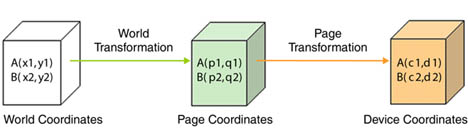
Before we discuss transformations, we need to understand coordinate systems. GDI+ defines three types of coordinate spaces: world, page, and device. When we ask GDI+ to draw a line from point A (x1, y1) to point B (x2, y2), these points are in the world coordinate system.
Before GDI+ draws a graphics shape on a surface, the shape goes through a few transformation stages (conversions). The first stage converts world coordinates to page coordinates. Page coordinates may or may not be the same as world coordinates, depending on the transformation. The process of converting world coordinates to page coordinates is called world transformation.
The second stage converts page coordinates to device coordinates. Device coordinates represent how a graphics shape will be displayed on a device such as a monitor or printer. The process of converting page coordinates to device coordinates is called page transformation. Figure 10.2 shows the stages of conversion from world coordinates to device coordinates.
Figure 10.2. Transformation stages
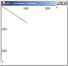
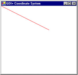
In GDI+, the default origin of all three coordinate systems is point (0, 0), which is at the upper left corner of the client area. When we draw a line from point A (0, 0) to point B (120, 80), the line starts 0 pixels from the upper left corner in the x-direction and 0 pixels from the upper left corner in the y-direction, and it will end 120 pixels over in the x-direction and 80 pixels down in the y-direction. The line from point A (0, 0) to point B (120, 80) is shown in Figure 10.3.
Figure 10.3. Drawing a line from point (0, 0) to point (120, 80)
Drawing this line programmatically is very simple. We must have a Graphics object associated with a surface (a form or a control). We can get a Graphics object in several ways. One way is to accept the implicit object provided by a form's paint event handler; another is to use the CreateGraphics method. Once we have a Graphics object, we call its draw and fill methods to draw and fill graphics objects. Listing 10.1 draws a line from starting point A (0, 0) to ending point B (120, 80). You can add this code to a form's paint event handler.
Listing 10.1 Drawing a line from point (0, 0) to point (120, 80)
Graphics g = e.Graphics;
Point A = new Point(0, 0);
Point B = new Point(120, 80);
g.DrawLine(Pens.Black, A, B);
Figure 10.3 shows the output from Listing 10.1. All three coordinate systems (world, page, and device) draw a line starting from point (0, 0) in the upper left corner of the client area to point (120, 80).
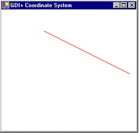
Now let's change to the page coordinate system. We draw a line from point A (0, 0) to point B (120, 80), but this time our origin is point (50, 40) instead of the upper left corner. We shift the page coordinates from point (0, 0) to point (50, 40). The TranslateTransform method of the Graphics class does this for us. We will discuss this method in more detail in the discussion that follows. For now, let's try the code in Listing 10.2.
Listing 10.2 Drawing a line from point (0, 0) to point (120, 80) with origin (50, 40)
Graphics g = e.Graphics;
g.TranslateTransform(50, 40);
Point A = new Point(0, 0);
Point B = new Point(120, 80);
g.DrawLine(Pens.Black, A, B);
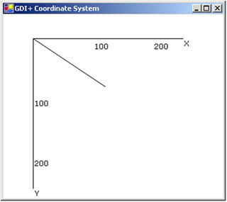
Figure 10.4 shows the output from Listing 10.2. The page coordinate system now starts at point (50, 40), so the line starts at point (0, 0) and ends at point (120, 80). The world coordinates in this case are still (0, 0) and (120, 80), but the page and device coordinates are (50, 40) and (170, 120). The device coordinates in this case are the same as the page coordinates because the page unit is in the pixel (default) format.
Figure 10.4. Drawing a line from point (0, 0) to point (120, 80) with origin (50, 40)
What is the difference between page and device coordinates? Device coordinates determine what we actually see on the screen. They can be represented in many formats, including pixels, millimeters, and inches. If the device coordinates are in pixel format, the page coordinates and device coordinates will be the same (this is typically true for monitors, but not for printers).
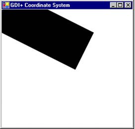
The PageUnit property of the Graphics class is of type GraphicsUnit enumeration. In Listing 10.3 we set the PageUnit property to inches. Now graphics objects will be measured in inches, so we need to pass inches instead of pixels. If we draw a line from point (0, 0) to point (2, 1), the line ends 2 inches from the left side and 1 inch from the top of the client area in the page coordinate system. In this case the starting and ending points are (0, 0) and (2, 1) in both world and page coordinates, but the device coordinate system converts them to inches. Hence the starting and ending points in the device coordinate system are (0, 0) and (192, 96), assuming a resolution of 96 dots per inch.
Listing 10.3 Setting the device coordinate system to inches
g.PageUnit = GraphicsUnit.Inch;
g.DrawLine(Pens.Black, 0, 0, 2, 1);
Figure 10.5 shows the output from Listing 10.3. The default width of the pen is 1 page unit, which in this case gives us a pen 1 inch wide.
Figure 10.5. Drawing with the GraphicsUnit.Inch option
Now let's create a new pen with a different width. Listing 10.4 creates a pen that's 1 pixel wide (it does so by dividing the number of pixels we wantin this case 1by the page resolution, which is given by DpiX). We draw the line again, this time specifying a red color.
Listing 10.4 Using the GraphicsUnit.Inch option with a pixel width
Pen redPen = new Pen(Color.Red, 1/g.DpiX);
g.PageUnit = GraphicsUnit.Inch;
g.DrawLine(Pens.Black, 0, 0, 2, 1);
Figure 10.6 shows the output from Listing 10.4.
Figure 10.6. Drawing with the GraphicsUnit.Inch option and a pixel width
We can also combine the use of page and device coordinates. In Listing 10.5 we transform page coordinates to 1 inch from the left and 0.5 inch from the top of the upper left corner of the client area. Our new page coordinate system has starting and ending points of (1, 0.5) and (3, 1.5), but the device coordinate system converts them to pixels. Hence the starting and ending points in device coordinates are (96, 48) and (288, 144), assuming a resolution of 96 dots per inch.
Listing 10.5 Combining page and device coordinates
Pen redPen = new Pen(Color.Red, 1/g.DpiX);
g.TranslateTransform(1, 0.5f);
g.PageUnit = GraphicsUnit.Inch;
g.DrawLine(redPen, 0, 0, 2, 1);
Figure 10.7 shows the output from Listing 10.5.
Figure 10.7. Combining page and device coordinates
GDI+: The Next-Generation Graphics Interface
- GDI+: The Next-Generation Graphics Interface
- Understanding GDI+
- Exploring GDI+ Functionality
- GDI+ from a GDI Perspective
- GDI+ Namespaces and Classes in .NET
- Summary
Your First GDI+ Application
- Your First GDI+ Application
- Drawing Surfaces
- The Coordinate System
- Tutorial: Your First GDI+ Application
- Some Basic GDI+ Objects
The Graphics Class
- The Graphics Class
- Graphics Class Properties
- Graphics Class Methods
- The GDI+Painter Application
- Drawing a Pie Chart
Working with Brushes and Pens
- Working with Brushes and Pens
- Understanding and Using Brushes
- Using Pens in GDI+
- Transformation with Pens
- Transformation with Brushes
- System Pens and System Brushes
- A Real-World Example: Adding Colors, Pens, and Brushes to the GDI+Painter Application
Colors, Fonts, and Text
- Colors, Fonts, and Text
- Accessing the Graphics Object
- Working with Colors
- Working with Fonts
- Working with Text and Strings
- Rendering Text with Quality and Performance
- Advanced Typography
- A Simple Text Editor
- Transforming Text
Rectangles and Regions
- Rectangles and Regions
- The Rectangle Structure
- The Region Class
- Regions and Clipping
- Clipping Regions Example
- Regions, Nonrectangular Forms, and Controls
Working with Images
- Working with Images
- Raster and Vector Images
- Working with Images
- Manipulating Images
- Playing Animations in GDI+
- Working with Bitmaps
- Working with Icons
- Skewing Images
- Drawing Transparent Graphics Objects
- Viewing Multiple Images
- Using a Picture Box to View Images
- Saving Images with Different Sizes
Advanced Imaging
- Advanced Imaging
- Rendering Partial Bitmaps
- Working with Metafiles
- Color Mapping Using Color Objects
- Image Attributes and the ImageAttributes Class
- Encoder Parameters and Image Formats
Advanced 2D Graphics
- Advanced 2D Graphics
- Line Caps and Line Styles
- Understanding and Using Graphics Paths
- Graphics Containers
- Reading Metadata of Images
- Blending Explained
- Alpha Blending
- Miscellaneous Advanced 2D Topics
Transformation
- Transformation
- Coordinate Systems
- Transformation Types
- The Matrix Class and Transformation
- The Graphics Class and Transformation
- Global, Local, and Composite Transformations
- Image Transformation
- Color Transformation and the Color Matrix
- Matrix Operations in Image Processing
- Text Transformation
- The Significance of Transformation Order
Printing
- Printing
- A Brief History of Printing with Microsoft Windows
- Overview of the Printing Process
- Your First Printing Application
- Printer Settings
- The PrintDocument and Print Events
- Printing Text
- Printing Graphics
- Print Dialogs
- Customizing Page Settings
- Printing Multiple Pages
- Marginal Printing: A Caution
- Getting into the Details: Custom Controlling and the Print Controller
Developing GDI+ Web Applications
- Developing GDI+ Web Applications
- Creating Your First ASP.NET Web Application
- Your First Graphics Web Application
- Drawing Simple Graphics
- Drawing Images on the Web
- Drawing a Line Chart
- Drawing a Pie Chart
GDI+ Best Practices and Performance Techniques
- GDI+ Best Practices and Performance Techniques
- Understanding the Rendering Process
- Double Buffering and Flicker-Free Drawing
- Understanding the SetStyle Method
- The Quality and Performance of Drawing
GDI Interoperability
Miscellaneous GDI+ Examples
- Miscellaneous GDI+ Examples
- Designing Interactive GUI Applications
- Drawing Shaped Forms and Windows Controls
- Adding Copyright Information to a Drawn Image
- Reading and Writing Images to and from a Stream or Database
- Creating Owner-Drawn List Controls
Appendix A. Exception Handling in .NET
- Chapter III Two Models of Online Patronage: Why Do Consumers Shop on the Internet?
- Chapter IV How Consumers Think About Interactive Aspects of Web Advertising
- Chapter VI Web Site Quality and Usability in E-Commerce
- Chapter XIV Product Catalog and Shopping Cart Effective Design
- Chapter XV Customer Trust in Online Commerce
