Advanced Cisco IPSec VPN Features
Cisco ASA provides many advanced features to suit your remote-access VPN implementations. Some of these features are listed here:
- Transparent tunneling
- IPSec hairpinning
- VPN load-balancing
- Client auto-update
- Client firewalling
- Easy VPN features
The sections that follow cover these features in more detail.
Transparent Tunneling
In many network topologies, the VPN clients reside behind a SOHO NAT/PAT device that inspects the Layer 4 port information for address translation. Because IPSec uses ESP (IP protocol 50), which does not have Layer 4 information, the NAT device is usually incapable of translating the encrypted packets going over the VPN tunnel. To remedy this problem, Cisco ASA offers three different options:
- NAT Traversal (NAT-T)
- IPSec over UDP
- IPSec over TCP
The sections that follow cover these options in greater detail.
NAT Traversal
NAT-T, currently an IETF draft, is a feature that encapsulates the ESP packets into UDP port 4500 packets. NAT-T is dynamically negotiated if the following two conditions are met:
- Both VPN devices are NAT-T capable
- A NAT or PAT device exists between VPN peers
If both conditions are true, the VPN client tries to connect to the security appliance using UDP port 500 for IKE negotiations. As soon as the VPN peers discover that they are NAT-T capable and a NAT/PAT device resides between them, they switch over to UDP port 4500 for the rest of tunnel negotiations and data encapsulation.
The command syntax to enable NAT-T globally on Cisco ASA is as follows:
crypto isakmp nat-traversal [keepalives]
Here, the keepalives range is between 10 and 3600 seconds. If you don't specify the keepalives range, Cisco ASA uses 20 seconds as the default. NAT-T keepalives are used to make sure that a NAT or PAT device does not age out the VPN tunnel on UDP port 4500. The security appliance sends periodic keepalives to keep them active even if there is no data flowing over the VPN connection.
If NAT-T is globally enabled, but if you do not want to use NAT-T for the remote-access tunnel, you can use the crypto dynamic-map set nat-t-disable option, the command syntax for which is as follows:
crypto dynamic-map map-name seq-num set nat-t-disable
Example 16-28 illustrates how to disable NAT-T for a dynamic map, called outside_dyn_map.
Example 16-28. Disabling NAT-T for Remote-Access Tunnels
Chicago(config)# crypto dynamic-map outside_dyn_map 20 set nat-t-disable
IPSec over TCP
IPSec over TCP is an important feature used in scenarios where:
- UDP port 500 is blocked, resulting in incomplete IKE negotiations.
- ESP (IP protocol 50) is not allowed to pass, and as a result encrypted traffic does not traverse.
- The network administrator prefers to use a connection-oriented protocol such as TCP.
With IPSec over TCP, the security appliance negotiates the VPN tunnel using TCP as the protocol over a preconfigured port. When the tunnel is up, both VPN devices (Cisco ASA and the VPN client) pass traffic using the same connection. Example 16-29 illustrates how to configure IPSec over TCP on Cisco ASA. The administrator of the box prefers to use TCP port 10000 for tunnel setup and data transport. Cisco ASA allows up to ten TCP ports to be used for this feature.
Example 16-29. IPSec over TCP Configuration
Chicago(config)# isakmp ipsec-over-tcp port 10000
To verify whether the VPN clients are using IPSec over TCP, you can use the show crypto ipsec sa | include settings command, as demonstrated in Example 16-30. The "in use settings" option indicates that the particular VPN connection is a remote-access tunnel using TCP encapsulation.
Example 16-30. Verifying VPN Client Use of IPSec over TCP
Chicago(config)# show crypto ipsec sa | include settings

 in use settings ={RA, Tunnel, TCP-Encaps, }

 in use settings ={RA, Tunnel, TCP-Encaps, }
IPSec over UDP
IPSec over UDP, similar to NAT-T, is used to encapsulate the ESP packets using a UDP wrapper. This is useful in scenarios where the VPN clients do not support NAT-T and are behind a firewall that does not allow ESP packets to pass through. In IPSec over UDP, the IKE negotiations still use UDP port 500. During the negotiations, Cisco ASA informs the VPN client to use IPSec over UDP for data transport. Additionally, Cisco ASA updates the VPN client about the UDP port it should use. Example 16-31 configures Cisco ASA to use IPSec over UDP for the remote-access group DfltGrpPolicy. Cisco ASA will push UDP port 10000 as the data encapsulation port to the VPN client.
Note
NAT-T is supported on Cisco VPN clients running version 3.6 or higher.
Example 16-31. IPSec over UDP Configuration
Chicago(config)# group-policy DfltGrpPolicy attributes

Chicago(config-group-policy)# ipsec-udp enable

Chicago(config-group-policy)# ipsec-udp-port 10000
IPSec Hairpinning
Cisco ASA does not allow a packet to leave the same interface on which it was originally received, because of security reasons. However, in case of an IPSec VPN tunnel, Cisco ASA supports receiving the IPSec traffic from one VPN tunnel and then redirecting it into the other one, if both tunnels terminate on the same interface. This feature is known as IPSec hairpinning. Using this feature, you can implement a true hub-and-spoke scenario, as shown in Figure 16-10. If Client1 needs to send traffic to Client2, it will send that traffic to the hub Cisco ASA. The hub Cisco ASA, after checking the routing table for the destination address, sends traffic to Client2 over the other VPN tunnel, and vice versa. However, this feature requires both remote VPN devices to be a part of the same crypto map. Additionally, the crypto map must be applied to the same interface.
Figure 16-10. IPSec Hairpinning
Example 16-32 shows the related IPSec configuration to implement the IPSec hairpinning feature. This configuration uses the same-security-traffic permit intra-interface command to permit VPN traffic to leave the same physical interface once traffic needs to go over the other VPN tunnel.
Example 16-32. IPSec Hairpinning
Chicago(config)# same-security-traffic permit intra-interface
Cisco ASA also supports receiving traffic over the VPN tunnel and then redirecting it back out to the Internet in clear text. This feature, also known as Client U-turn, is useful if you do not want the VPN traffic destined to the Internet to enter the inside network of your organization.
Cisco ASA applies firewall rules (ACL checking, packet inspection, NAT, IDS, URL filtering) before sending traffic out to the same interface for both IPSec hairpinning and Client U-turn.
VPN Load-Balancing
VPN load-balancing is a way to distribute remote-access VPN and WebVPN connections across multiple security appliances. When two or more Cisco ASA devices are deployed in load-balancing, they form a virtual cluster, with one of the security appliances acting as the cluster master. All Cisco ASA devices in the cluster are configured with a virtual IP address, and the cluster master takes ownership of that IP address, as illustrated in Figure 16-11.
Figure 16-11. HTTP VPN Load-Balancing
The VPN clients use this IP address to initiate the tunnel request. The master appliance, after receiving the request, looks at the load-balance database and determines which security appliance has the least load. The master appliance sends a redirect message back to the client with the IP address of the security appliance the client should connect to. The client, after receiving the IP address of the Cisco ASA, initiates a new request to the Cisco ASA and goes through the IKE negotiations.
Note
Cisco ASA load-balancing feature is fully compatible with the load-balancing feature on the VPN3000 concentrators.
To set up VPN load-balancing, the first thing to do is to get into the load-balancing submenu. This is achieved by issuing the vpn load-balancing command from configuration mode, as shown in Example 16-33. The Cisco ASA devices are configured to use a virtual IP address of 209.165.200.227, which will be used on the VPN clients as the primary host address. The last step in setting up load-balancing is to enable it by using the participate command.
Example 16-33. VPN Load-Balancing Configuration
Chicago(config)# vpn load-balancing

Chicago(config-load-balancing))# cluster ip address 209.165.200.227

Chicago(config-load-balancing))# participate
If the Cisco ASA devices are behind a firewall using NAT, then you can configure the translated IP address using the nat command under the load-balancing submenu, as illustrated in Example 16-34. The virtual IP address is 209.165.200.227, but the firewall is translating this address to 209.165.202.140.
Example 16-34. VPN Load-Balancing Configuration with NAT
Chicago(config)# vpn load-balancing

Chicago(config-load-balancing)# nat 209.165.202.140

Chicago(config-load-balancing)# cluster ip address 209.165.200.227
Additionally, you can set the appropriate priority to indicate the likelihood of a Cisco ASA device becoming the cluster master either during bootup or when the existing cluster master fails to respond. The default priority of Cisco ASA devices is determined based on the model number. Table 16-3 lists all the default priorities of the Cisco ASA devices.
|
Cisco ASA Model |
Default Priority |
|---|---|
|
ASA 5520 |
5 |
|
ASA 5540 |
7 |
If two Cisco ASA devices with the same priority are powered up simultaneously, then the security appliance with the lowest IP address becomes the cluster master. Otherwise, the security appliance with the highest priority assumes the role of master cluster.
Note
Cisco ASA 5510 does not support VPN load-balancing.
If the cluster master fails to respond during operation, the secondary appliance with the highest priority becomes the new cluster master. The default priority of an appliance can be changed by using the priority command in the load-balancing menu. You can specify a priority between 1 and 10. When the original master appliance comes online, it does not preempt to regain control.
Tip
Cisco ASA uses UDP port 9023 when communicating in the load-balancing cluster. However, you can change this port by using the cluster port command.
Cisco ASA also allows you to set up a secured connection between the security appliances when they exchange load-balancing information. This is achieved by using the cluster encryption and cluster key commands. In Example 16-35, a key of cisco123 is used to encrypt traffic between the security appliances in the cluster. If there is a mismatch in the key, the security appliance fails to join the cluster.
Example 16-35. VPN Load-Balancing Configuration with Encryption
Chicago(config)# vpn load-balancing

Chicago(config-load-balancing)# priority 9

Chicago(config-load-balancing)# cluster key cisco123

Chicago(config-load-balancing)# cluster ip address 209.165.200.227

Chicago(config-load-balancing)# cluster encryption

Chicago(config-load-balancing)# participate
Note
VPN load-balancing requires you to enable ISAKMP on all the interfaces participating in load-balancing.
Client Auto-Update
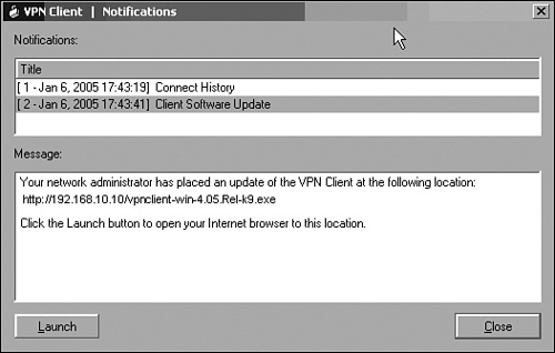
The client auto-update feature helps you to ensure that all of the Cisco VPN clients (whether software or hardware based) are running the same version of code. When a software-based VPN client connects to Cisco ASA, it sends its software version information to the security appliance. Cisco ASA checks the received version with the configured revision of code. If the received and configured revised versions do not match, the security appliance sends a notification back to the client informing it to download the newer version. This notification is sent after the tunnel is established and it contains a link of an HTTP or HTTPS server that stores the Cisco VPN client image. Once the user clicks the link, the image is downloaded in the machine and the upgrade process can start.
Note
Cisco ASA supports only Windows-based software VPN clients for auto-update.
Example 16-36 shows the configuration for Cisco ASA to use the client auto-update feature for the ciscovpn tunnel group. The client auto-update feature is configured by using the client-update command under the ipsec-attributes submenu of the group to which all the Windows (including 95, 98, Me, NT, 2000, and XP) VPN clients connect. The software VPN client software image is stored on an HTTP server with an IP address of 192.168.10.10, and the image name is vpnclient-win-4.05.Rel-k9.exe. Cisco ASA checks the received revision number with the configured revision of 4.05.Rel. If the revision numbers do not match, Cisco ASA sends a notification to the VPN client, as shown in Figure 16-12. Once Cisco ASA is set up for the update URL, the final step is to enable it globally by using the client-update enable command.
Figure 16-12. Notification Message Sent to the Client
Example 16-36. Client Auto-Update Feature on a Tunnel Group
Chicago(Config)# tunnel-group ciscovpn ipsec-attributes

Chicago(Config-ipsec)# client-update type Windows url http://192.168.10.10/

 vpnclient-win-4.05.Rel-k9.exe rev-nums 4.05.Rel

Chicago(Config-ipsec)# exit

Chicago(Config)# client-update enable
Note
If you want to update software only on particular Windows operating systems, you can specify the OS-specific keyword, such as Win9X for Windows 95, 98, and Me, and WinNT for Windows NT, 2000, and XP.
Additionally, if you want all Windows clients to get notified with the new image regardless of their tunnel group membership, you can configure the client auto-update in global configuration mode, as demonstrated in Example 16-37.
Example 16-37. Client Auto-Update Feature in Global Configuration Mode
Chicago(Config)# client-update type Windows url http://192.168.10.10/vpnclient-win-

 4.05.Rel-k9.exe rev-nums 4.05.Rel

Chicago(Config)# client-update enable
The client auto-update feature works differently for the Cisco VPN 3002 Hardware Client. When the security appliance detects that the Cisco VPN 3002 HW Client is running a different image, it sends a notification along with the URL of a TFTP server. The VPN 3002 HW Client starts the upgrade process automatically without user interruption. After downloading the image, it reboots itself to load the new code. Example 16-38 shows the configuration excerpt from the Chicago ASA, which is set up with the client auto-update feature for the Cisco VPN 3002 HW clients. The image is stored on a TFTP server with an IP address of 192.168.10.10 and an image name of vpn3002-4.7.2.Rel-k9.bin.
Example 16-38. Client-Update Feature for Cisco VPN 3002 HW Clients
Chicago(config)# client-update type vpn3002 url tftp://192.168.10.10/vpn3002-

 4.7.2.Rel-k9.bin rev-nums 4.7.2

Chicago(config)# client-update enable
Client Firewalling
The Cisco VPN client has an integrated personal firewall that protects a machine from the Internet by inspecting packets both inbound and outbound. By having the firewall option enabled on the VPN client, the client provides extra security if the VPN group the user is connecting to has split tunneling enabled. In this way, the firewall denies packets received from the unprotected networks, resulting in securing corporate networks from unauthorized intruders. Cisco ASA supports two different scenarios for client firewalling, discussed in the sections that follow.
Note
Only Windows VPN clients support the client firewalling feature.
Personal Firewall Check
The Cisco VPN client can check to see if the firewall service on the machine is running by sending periodic keepalives, also known as "Are you there" (AYT) messages, to the specified firewall. If the firewall service on the client machine is not running, the VPN client fails to establish the secured connection. Additionally, if the VPN tunnel is up and the user manually turns off the firewall service, the keepalives time out and the Cisco VPN client drops the connection. An administrator can set up Cisco ASA for three firewall check modes:
- no firewall The personal firewall check is disabled. This mode is useful if non-Windows clients are connecting to a group.
- firewall optional Cisco ASA checks to see if the firewall services on the VPN client are running. If they are disabled, Cisco ASA still allows the VPN connection to come up. This mode is useful if Windows and non-Windows clients connect to a group.
- firewall required If the firewall service is not running, Cisco ASA will not allow the VPN tunnel to be established. This mode is recommended if Windows clients connect to a group.
All of these modes are configured under the group configuration menu using the client-firewall command, as shown in Example 16-39.
Example 16-39. Modes in Client Firewall
Chicago(config)# group-policy ciscovpn attributes

Chicago(config-group-policy)# client-firewall ?

 none No firewall is required for remote users in this group

 opt optional

 req required
For optional (opt) and required (req) modes, Cisco ASA provides a list of currently supported personal firewalls, including the built-in Cisco Integrated Client Firewall, as shown in Example 16-40. This example also shows that Zone Labs' ZoneAlarm Pro is the required firewall. If the VPN clients don't have this firewall running, Cisco ASA will stop the tunnels from getting formed.
Example 16-40. List of Supported Firewalls
Chicago(config-group-policy)# client-firewall req ?


 cisco-integrated Cisco Integrated Client Firewall

 cisco-security-agent Cisco Security Agent

 custom Custom Firewall

 networkice-blackice Network ICE BlackICE Defender

 sygate-personal Sygate Personal Firewall

 sygate-personal-pro Sygate Personal Firewall Pro

 sygate-security-agent Sygate Security Agent

 zonelabs-zonealarm Zone Labs ZoneAlarm

 zonelabs-zonealarmorpro Zone Labs ZoneAlarm or ZoneAlarm Pro

 zonelabs-zonealarmpro Zone Labs ZoneAlarm Pro

Chicago(config-group-policy)# client-firewall req zonelabs-zonealarmpro policy AYT
Note
You can define a customized firewall if you know the vendor ID and product ID, by using the custom keyword.
Central Protection Policy
When split tunneling is employed, Cisco ASA can additionally send security policies to the client machine and restrict its clear-text traffic capabilities. This deployment scenario, known as Centralized Protection Policy (CPP) or policy pushed, uses ACLs that can be pushed to the client firewall. This ensures that traffic matching the permitted entries is allowed to pass through, and the unwanted traffic is filtered out.
Example 16-41 shows that Cisco ASA requires that the VPN client use the Cisco Integrated Client Firewall (CIC). Cisco ASA also restricts the client machine to send and receive traffic based on the configured inbound ACL, named Inbound_FW_ACL, and the outbound ACL, named Outbound_FW_ACL. These ACLs allow IP traffic only from 192.168.100.0/24 to 192.168.50.0/24 and vice versa.
Example 16-41. Configuration of Central Protection Policy
Chicago(config)# access-list Inbound_FW_ACL extended permit ip 192.168.100.0

 255.255.255.0 192.168.50.0 255.255.255.0

Chicago(config)# access-list Outbound_FW_ACL extended permit ip 192.168.50.0

 255.255.255.0 192.168.100.0 255.255.255.0

Chicago(config)# group-policy SecureMeGrp attributes

Chicago(config-group-policy)# client-firewall req cisco-integrated acl-in

 Inbound_FW_ACL acl-out Outbound_FW_ACL
Hardware based Easy VPN Client Features
Cisco ASA can provide further security for the Hardware based Easy VPN client that is connecting to it by controlling specific features, as discussed in the sections that follow.
Interactive Hardware Client Authentication
Cisco ASA can use the interactive hardware client authentication feature, also known as secure unit authentication, which ensures that the Hardware based Easy VPN client provides user credentials every time the tunnel is negotiated. That way, the security appliance does not allow user passwords to be saved on the hardware based Easy VPN client, which provides additional security. If the user password is saved on the hardware based Easy VPN client, Cisco ASA pushes down a policy during mode-config to delete the saved password from the hardware based Easy VPN client configuration. The interactive hardware client authentication is configured under group parameters using the secure-unit-authentication command followed by the enable or disable option. Example 16-42 shows configuration to set up Cisco ASA for interactive hardware client authentication for the SecureMeGrp group.
Example 16-42. Configuration of Interactive Client Authentication
Chicago(config)# group-policy SecureMeGrp attributes

Chicago(config-group-policy)# secure-unit-authentication enable
Individual User Authentication
Using the Individual User Authentication feature, Cisco ASA secures the VPN tunnel by making sure that users behind the Hardware based Easy VPN Client are authenticated before they can access corporate resources. To be able to pass traffic over the tunnel, a user behind the hardware based Easy VPN client must launch a web browser and present valid user credentials. The hardware based Easy VPN client forwards the user information to Cisco ASA, which in turn validates the user information using the configured authentication method.
Tip
The user does not have to manually point the web browser to the IP address of the Hardware based Easy VPN client. Instead, users can try to browse to any server behind the security appliance, and the hardware based Easy VPN client will redirect them for user credentials.
The Individual User Authentication is configured under group parameters using the user-authentication command followed by the enable or disable option. Example 16-43 shows the Cisco ASA configuration for Individual User Authentication for the SecureMeGrp group.
Example 16-43. Configuration of Individual User Authentication
Chicago(config)# group-policy SecureMeGrp attributes

Chicago(config-group-policy)# user-authentication enable
You can specify the idle-time period if there is no activity over a user's connection. When the idle-time period expires, Cisco ASA terminates that particular connection. The timeout period can be enabled by using the user-authentication-idle-timeout command followed by the timeout value in minutes. In Example 16-44, group SecureMeGrp is configured to time out inactive users after 10 minutes.
Example 16-44. Configuration of Individual User Timeout
Chicago(config)# group-policy SecureMeGrp attributes

Chicago(config-group-policy)# user-authentication-idle-timeout 10
Note
The user authentication is done based on the source IP address of the clients.
Cisco IP Phone Bypass
When individual hardware client authentication is enabled, Cisco ASA tries to authenticate Cisco IP Phones if they send traffic to go over the tunnel. You can set up the security appliance to bypass authentication for Cisco IP Phones by configuring the ip-phone-bypass command under a group-policy, as shown in Example 16-45.
Example 16-45. Configuration of Cisco IP Phone Bypass
Chicago(config)# group-policy SecureMeGrp attributes

Chicago(config-group-policy)# ip-phone-bypass enable
Note
For this feature to work, make sure that the hardware based Easy VPN client is using network extension mode.
Leap Bypass
Leap bypass is a feature in the security appliance that allows the Lightweight Extensible Authentication Protocol (LEAP) packets to go over the VPN tunnel when individual hardware client authentication is configured. LEAP bypass is configured under group parameters using the leap-bypass command followed by the enable or disable option. Example 16-46 shows the Cisco ASA configuration for LEAP bypass for the SecureMeGrp group.
Example 16-46. Configuration of Cisco Aironet LEAP Bypass
Chicago(config)# group-policy SecureMeGrp attributes

Chicago(config-group-policy)# leap-bypass enable
Note
This feature only works with Cisco Aironet access points using LEAP for authentication.
Hardware Client Network Extension Mode
You have the option to configure a group-policy to disable network extension mode (NEM) on Cisco ASA. When you use this option, the hardware based Easy VPN clients are restricted to using client/PAT mode for VPN tunnels. If they try to use NEM, Cisco ASA blocks the tunnel from being established. NEM is configured under group parameters using the nem command followed by the enable or disable option. Example 16-47 shows the Cisco ASA configuration to allow NEM for the SecureMeGrp group.
Example 16-47. Configuration to Allow NEM for Hardware based Easy VPN Clients
Chicago(config)# group-policy SecureMeGrp attributes

Chicago(config-group-policy)# nem enable
Part I: Product Overview
Introduction to Network Security
- Introduction to Network Security
- Firewall Technologies
- Intrusion Detection and Prevention Technologies
- Network-Based Attacks
- Virtual Private Networks
- Summary
Product History
- Product History
- Cisco Firewall Products
- Cisco IDS Products
- Cisco VPN Products
- Cisco ASA All-in-One Solution
- Summary
Hardware Overview
Part II: Firewall Solution
Initial Setup and System Maintenance
- Initial Setup and System Maintenance
- Accessing the Cisco ASA Appliances
- Managing Licenses
- Initial Setup
- IP Version 6
- Setting Up the System Clock
- Configuration Management
- Remote System Management
- System Maintenance
- System Monitoring
- Summary
Network Access Control
- Network Access Control
- Packet Filtering
- Advanced ACL Features
- Content and URL Filtering
- Deployment Scenarios Using ACLs
- Monitoring Network Access Control
- Understanding Address Translation
- DNS Doctoring
- Monitoring Address Translations
- Summary
IP Routing
Authentication, Authorization, and Accounting (AAA)
- Authentication, Authorization, and Accounting (AAA)
- AAA Protocols and Services Supported by Cisco ASA
- Defining an Authentication Server
- Configuring Authentication of Administrative Sessions
- Authenticating Firewall Sessions (Cut-Through Proxy Feature)
- Configuring Authorization
- Configuring Accounting
- Deployment Scenarios
- Troubleshooting AAA
- Summary
Application Inspection
- Application Inspection
- Enabling Application Inspection Using the Modular Policy Framework
- Selective Inspection
- Computer Telephony Interface Quick Buffer Encoding Inspection
- Domain Name System
- Extended Simple Mail Transfer Protocol
- File Transfer Protocol
- General Packet Radio Service Tunneling Protocol
- H.323
- HTTP
- ICMP
- ILS
- MGCP
- NetBIOS
- PPTP
- Sun RPC
- RSH
- RTSP
- SIP
- Skinny
- SNMP
- SQL*Net
- TFTP
- XDMCP
- Deployment Scenarios
- Summary
Security Contexts
- Security Contexts
- Architectural Overview
- Configuration of Security Contexts
- Deployment Scenarios
- Monitoring and Troubleshooting the Security Contexts
- Summary
Transparent Firewalls
- Transparent Firewalls
- Architectural Overview
- Transparent Firewalls and VPNs
- Configuration of Transparent Firewall
- Deployment Scenarios
- Monitoring and Troubleshooting the Transparent Firewall
- Summary
Failover and Redundancy
- Failover and Redundancy
- Architectural Overview
- Failover Configuration
- Deployment Scenarios
- Monitoring and Troubleshooting Failovers
- Summary
Quality of Service
- Quality of Service
- Architectural Overview
- Configuring Quality of Service
- QoS Deployment Scenarios
- Monitoring QoS
- Summary
Part III: Intrusion Prevention System (IPS) Solution
Intrusion Prevention System Integration
- Intrusion Prevention System Integration
- Adaptive Inspection Prevention Security Services Module Overview (AIP-SSM)
- Directing Traffic to the AIP-SSM
- AIP-SSM Module Software Recovery
- Additional IPS Features
- Summary
Configuring and Troubleshooting Cisco IPS Software via CLI
- Configuring and Troubleshooting Cisco IPS Software via CLI
- Cisco IPS Software Architecture
- Introduction to the CIPS 5.x Command-Line Interface
- User Administration
- AIP-SSM Maintenance
- Advanced Features and Configuration
- Summary
Part IV: Virtual Private Network (VPN) Solution
Site-to-Site IPSec VPNs
- Site-to-Site IPSec VPNs
- Preconfiguration Checklist
- Configuration Steps
- Advanced Features
- Optional Commands
- Deployment Scenarios
- Monitoring and Troubleshooting Site-to-Site IPSec VPNs
- Summary
Remote Access VPN
- Remote Access VPN
- Cisco IPSec Remote Access VPN Solution
- Advanced Cisco IPSec VPN Features
- Deployment Scenarios of Cisco IPSec VPN
- Monitoring and Troubleshooting Cisco Remote Access VPN
- Cisco WebVPN Solution
- Advanced WebVPN Features
- Deployment Scenarios of WebVPN
- Monitoring and Troubleshooting WebVPN
- Summary
Public Key Infrastructure (PKI)
- Public Key Infrastructure (PKI)
- Introduction to PKI
- Enrolling the Cisco ASA to a CA Using SCEP
- Manual (Cut-and-Paste) Enrollment
- Configuring CRL Options
- Configuring IPSec Site-to-Site Tunnels Using Certificates
- Configuring the Cisco ASA to Accept Remote-Access VPN Clients Using Certificates
- Troubleshooting PKI
- Summary
Part V: Adaptive Security Device Manager
Introduction to ASDM
- Introduction to ASDM
- Setting Up ASDM
- Initial Setup
- Functional Screens
- Interface Management
- System Clock
- Configuration Management
- Remote System Management
- System Maintenance
- System Monitoring
- Summary
Firewall Management Using ASDM
- Firewall Management Using ASDM
- Access Control Lists
- Address Translation
- Routing Protocols
- AAA
- Application Inspection
- Security Contexts
- Transparent Firewalls
- Failover
- QoS
- Summary
IPS Management Using ASDM
- IPS Management Using ASDM
- Accessing the IPS Device Management Console from ASDM
- Configuring Basic AIP-SSM Settings
- Advanced IPS Configuration and Monitoring Using ASDM
- Summary
VPN Management Using ASDM
- VPN Management Using ASDM
- Site-to-Site VPN Setup Using Preshared Keys
- Site-to-Site VPN Setup Using PKI
- Cisco Remote-Access IPSec VPN Setup
- WebVPN
- VPN Monitoring
- Summary
Case Studies
EAN: 2147483647
Pages: 231
