REMEZ EXCHANGE FIR FILTER DESIGN METHOD
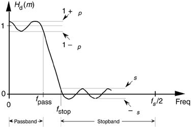
Let's introduce one last FIR filter design technique that has found wide acceptance in practice. The Remez Exchange FIR filter design method (also called the Parks-McClellan, or Optimal method) is a popular technique used to design high-performance FIR filters.[ ] To use this design method, we have to visualize a desired frequency response Hd(m) like that shown in Figure 5-30.
[
] Remez is pronounced re-'m
.
Figure 5-30. Desired frequency response definition of a low-pass FIR filter using the Remez Exchange design method.

We have to establish a desired passband cutoff frequency fpass and the frequency where the attenuated stopband begins, fstop. In addition, we must establish the variables dp and ds that define our desired passband and stopband ripple. Passband and stopband ripples, in decibels, are related to dp and ds by[15]

and
Equation 5-22'

(Some of the early journal papers describing the Remez design method used the equally valid expression –20 · log10(dp) to define the passband ripple in decibels. However, Eq. (5-22) is the most common form used today.) Next, we apply these parameters to a computer software routine that generates the filter's N time-domain h(k) coefficients where N is the minimum number of filter taps to achieve the desired filter response.
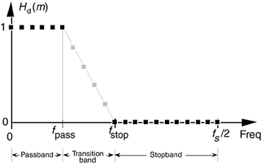
On the other hand, some software Remez routines assume that we want dp and ds to be as small as possible and require us only to define the desired values of the Hd(m) response as shown by the solid black dots in Figure 5-31. The software then adjusts the values of the undefined (shaded dots) values of Hd(m) to minimize the error between our desired and actual frequency response while minimizing dp and ds. The filter designer has the option to define some of the Hd(m) values in the transition band, and the software calculates the remaining undefined Hd(m) transition band values. With this version of the Remez algorithm, the issue of most importance becomes how we define the transition region. We want to minimize its width while, at the same time, minimizing passband and stopband ripple. So exactly how we design an FIR filter using the Remez Exchange technique is specific to the available filter design software. Although the mathematics involved in the development of the Remez Exchange method is rather complicated, we don't have to worry about that here[16–20]. Just remember that the Remez Exchange design method gives us a Chebyshev-type filter whose actual frequency response is as close as possible to the desired Hd(m) response for a given number of filter taps.
Figure 5-31. Alternate method for defining the desired frequency response of a low-pass FIR filter using the Remez Exchange technique.

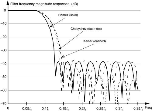
To illustrate the advantage of the Remez method, the solid curve in Figure 5-32 shows the frequency response of a 31-tap FIR designed using this technique. For comparison, Figure 5-32 also shows the frequency responses of two 31-tap FIR filters for the same passband width using the Chebyshev and Kaiser windowing techniques. Notice how the three filters have roughly the same stopband sidelobe levels, near the main lobe, but that the Remez filter has the more desirable (steeper) transition band roll-off.
Figure 5-32. Frequency response comparison of three 31-tap FIR filters: Remez, Chebyshev windowed, and Kaiser windowed.

URL http://proquest.safaribooksonline.com/0131089897/ch05lev1sec6
 |
Amazon |  |
