AN INTRODUCTION TO INFINITE IMPULSE RESPONSE FILTERS
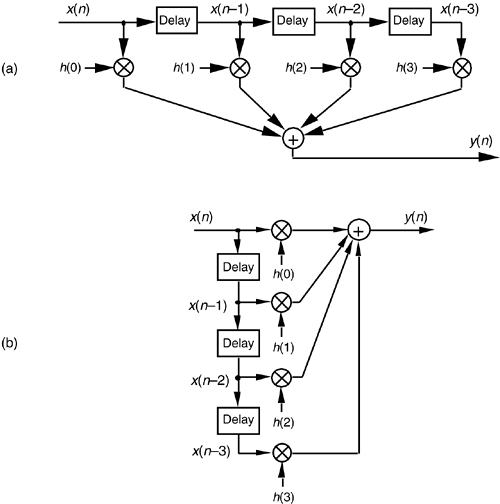
IIR filters get their name from the fact that some of the filter's previous output samples are used to calculate the current output sample. Given a finite duration of nonzero input values, the effect is that an IIR filter could have a infinite duration of nonzero output samples. So, if the IIR filter's input suddenly becomes a sequence of all zeros, the filter's output could conceivably remain nonzero forever. This peculiar attribute of IIR filters comes about because of the way they're realized, i.e., the feedback structure of their delay units, multipliers, and adders. Understanding IIR filter structures is straightforward if we start by recalling the building blocks of an FIR filter. Figure 6-2(a) shows the now familiar structure of a 4-tap FIR digital filter that implements the time-domain FIR equation

Figure 6-2. FIR digital filter structures: (a) traditional FIR filter structure; (b) rearranged, but equivalent, FIR filter structure.

Although not specifically called out as such in Chapter 5, Eq. (6-1) is known as a difference equation. To appreciate how past filter output samples are used in the structure of IIR filters, let's begin by reorienting our FIR structure in Figure 6-2(a) to that of Figure 6-2(b). Notice how the structures in Figure 6-2 are computationally identical, and both are implementations, or realizations, of Eq. (6-1).
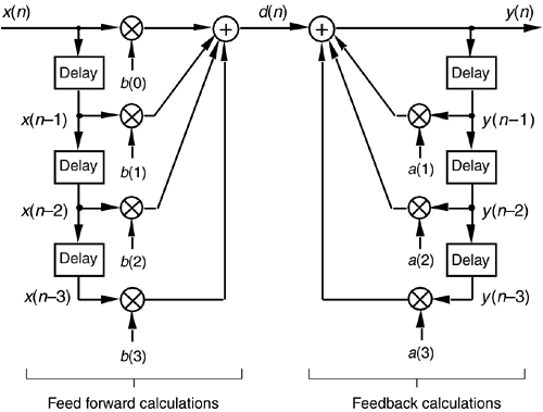
We can now show how past filter output samples are combined with past input samples by using the IIR filter structure in Figure 6-3. Because IIR filters have two sets of coefficients, we'll use the standard notation of the variables b(k) to denote the feed forward coefficients and the variables a(k) to indicate the feedback coefficients in Figure 6-3. OK, the difference equation describing the IIR filter in Figure 6-3 is
Equation 6-2

Figure 6-3. IIR digital filter structure showing feed forward and feedback calculations.

Look at Figure 6-3 and Eq. (6-2) carefully. It's important to convince ourselves that Figure 6-3 really is a valid implementation of Eq. (6-2) and that, conversely, difference equation Eq. (6-2) fully describes the IIR filter structure in Figure 6-3. Keep in mind now that the sequence y(n) in Figure 6-3 is not the same y(n) sequence that's shown in Figure 6-2. The d(n) sequence in Figure 6-3 is equal to the y(n) sequence in Figure 6-2.
By now you're probably wondering, "Just how do we determine those a(k) and b(k) IIR filter coefficients if we actually want to design an IIR filter?" Well, fasten your seat belt because this is where we get serious about understanding IIR filters. Recall from the last chapter concerning the window method of low-pass FIR filter design that we defined the frequency response of our desired FIR filter, took the inverse Fourier transform of that frequency response, and then shifted that transform result to get the filter's time-domain impulse response. Happily, due to the nature of transversal FIR filters, the desired h(k) filter coefficients turned out to be exactly equal to the impulse response sequence. Following that same procedure with IIR filters, we could define the desired frequency response of our IIR filter and then take the inverse Fourier transform of that response to yield the filter's time-domain impulse response. The bad news is that there's no direct method for computing the IIR filter's a(k) and b(k) coefficients from the impulse response! Unfortunately, the FIR filter design techniques that we've learned so far simply cannot be used to design IIR filters. Fortunately for us, this wrinkle can be ironed out by using one of several available methods of designing IIR filters.
Standard IIR filter design techniques fall into three basic classes: the impulse invariance, bilinear transform, and optimization methods. These design methods use a discrete sequence, mathematical transformation process known as the z-transform whose origin is the Laplace transform traditionally used in the analyzing of continuous systems. With that in mind, let's start this IIR filter analysis and design discussion by briefly reacquainting ourselves with the fundamentals of the Laplace transform.
URL http://proquest.safaribooksonline.com/0131089897/ch06lev1sec1
 |
Amazon |  |
